曲面模型建構
![]()
![]()
![]()
簡介
A surface is a single sided representation of a part's exterior that does not have a mass or thickness.
Surface modeling is a modeling approach that allows designers to create complex geometric features and organic shapes that solid modeling tools cannot produce alone. Surface modeling is used for more free-form shapes and features than solid modeling.
For example, a solid cube can be broken out into six different faces. Each face represents a surface that encloses the solid volume to form the cube. Surfacing lets you build each face of the cube as an individual surface. After all six sides of the cube are built, the surfaces are added together, and an enclosed volume is created, forming a solid part.
Surface geometry is used to:
-
Create a solid part:
-
Using the Thicken feature, a surface is thickened to form a solid part.
-
Using the Enclose feature, a solid part is created by forming a closed volume, where every edge bounds 2 faces.
-
-
Create construction geometry (split lines for molds, blending and bridging geometry together, supporting lofts and fills for matching curvature and tangency).
-
Replace a solid part face with more complex geometry (using the Replace face feature).
Curve and surface continuity is a measure of the smoothness of the between 2 curves or 2 surfaces where they connect. As curves and surfaces are built up to create geometric models, continuity becomes important in order to create the most fluid or continuous organic shape.
The G (or Geometry) designation is used to determine curve/surface continuity (G0 to G3). In Onshape, these designations correlate to the "Match" options in many curve and surface features (for example, Bridging curves, Fillet, Face blend, and others). These continuity classifications are outlined below, along with their definitions:
-
G0 (Match position) - The position is matched between the 2 curves/surfaces. Both curves/surfaces share a common position at the joint.
-
G1 (Match tangent) - Tangency is matched between the 2 curves/surfaces. Both curves/surfaces touch and share a common angle that is equal at both ends. A fillet is a good example of this type of continuity match.
-
G2 (Match curvature) - Curvature (radius) is matched between the 2 curves/surfaces. Both curves/surfaces touch, are tangent, and have the same curvature at the point where they touch (they both have identical radii).
-
G3 (Match flow) - Flow is matched between the 2 curves/surfaces. Both curves/surfaces touch, are tangent, have similar curvature, and show the amount of change in the curvature over the curvature's length (flow).
Using the Bridging curve feature, you can create a bridging curve (shown below in orange) between two curves and match its start and end position, tangency, curvature, and flow (or some combination between the two; for instance, Match position at the start and Match curvature at the end):

From left to right: G0 (Match position), G1 (Match tangent), G2 (Match curvature), G3 (Match flow)
Extending this beyond curves, you can create a surface between 2 surfaces, and match its start and end continuity in the same way:

From left to right: G0 (Match position), G1 (Match tangent), G2 (Match curvature), G3 (Match flow)
When analyzing curve or surface continuity using the Curve/surface analysis tool, you can see that with each progressive continuity match, the connections between the curves/surfaces becomes smoother and show smoother curvature combs. G0 (Match position) cannot be analyzed using the Curve/surface analysis because a straight line has no curvature.

From left to right: G1 (Match tangent), G2 (Match curvature), G3 (Match flow)

From left to right: G1 (Match tangent), G2 (Match curvature), G3 (Match flow)
When analyzing curve or surface continuity using the Zebra stripes tool, with each progressive continuity match, the connection between the curves/surfaces becomes smoother. Zebra stripes at the surface edges become increasingly smooth as you go up from G0 (Match position) to G2 (Match continuity):

From left to right: G0 (No continuity), G1 (Match tangent), and G2 (Match curvature)
The following examples illustrate the continuities on a bridging curve between two other non-linear curves. The bridging curve is colored magenta. The first column shows the Bridging curve dialog and continuity selection with the result (and Edit control points enabled), the middle column shows the bridging curve with Edit control points disabled, and the final column shows the Curve/surface analysis for all curves:
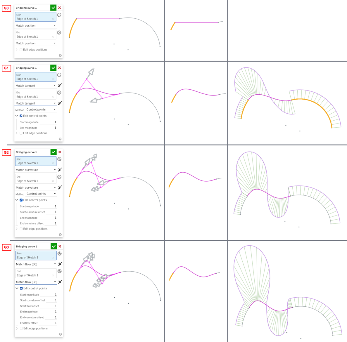
The continuity selected for the curve and surface connections in your model depends entirely on the level of continuity required at each junction/edge. There is no right or wrong surface continuity.
Additionally, higher orders of continuity require more control points to enforce. G0 needs only one control point (the endpoint), G1 needs two, G2 needs three, and G3 needs four. A Bezier curve that is G3 constrained at both ends requires at least eight control points, four for each end.
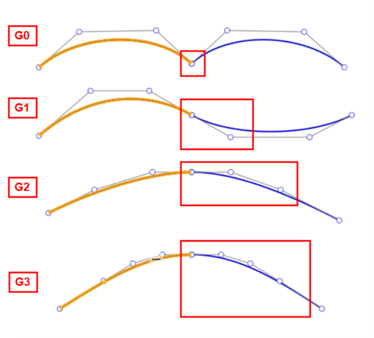
Modeling with surfaces requires additional steps to create high quality surfaces, These steps increase performance, avoid imperfections, and streamline complex surface creation.
-
Curve/surface analysis - Visualize and analyze curvature on a sketch in the Part Studio. Access the Curve/surface analysis dialog by clicking Shift+c, right-clicking on a sketch, part, or surface, or clicking the Show analysis tools icon (
 ) at the interface's bottom right corner.
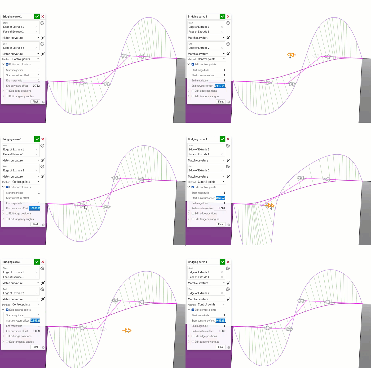
These tools show curvature combs (the intensity of the curvature at a certain point along an edge or face), and control point grids. Ideally, the curvature combs should have steady increases or decreases.
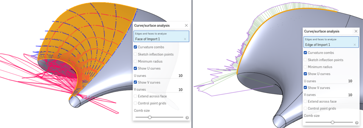
The following example looks good without evaluation tools but shows extreme fluctuations in curvature (especially in the red U direction below left) when Curvature/surface analysis is enabled. The outer edge is especially problematic (below right):
Additionally, the control point grid is a measure of the complexity of the surface. The flow and density of control points can illustrate a model with too many control points:
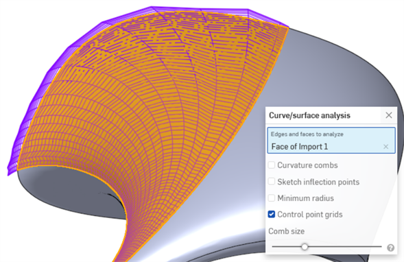
-
Connection analysis - Assess or report the connection between curves and surfaces in a Part Studio or Sketch. Access the Connection analysis dialog from the Show analysis tools icon (
 ) at the bottom right corner of the interface. Select curves or surfaces to analyze; the dialog box (shown below) populates with results automatically upon selection, along with color coordinated indicators in the graphics area.
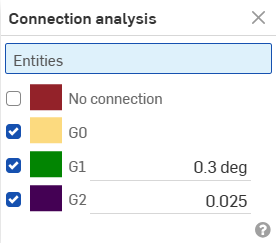
-
Zebra stripes and Color map - Zebra stripes represent the reflection of a striped room on the current model, faces, or surfaces in a Part Studio or Assembly. This allows you to see whether or not the curvature across edges and faces are aligned and continuous. Access Zebra stripes from the Show analysis tools icon (
 ) at the bottom right corner of the interface.
Zebra stripes do not match up with G0 or positional continuity. In G1 or tangency continuity, they match up directly on the edge but diverge sharply. In G2 or curvature continuity, the zebra stripes pass smoothly through the edge (shown below left). Zebra stripes also allow you to see defects or imperfections in the surface (shown below right):

-
Curvature color map - Enables deeper investigation of curvature by applying a gradient of color of your choosing onto a face or surface in a Part Studio. Adjust the scale of the color gradient and choose from different types of color maps to gain the best visual representation to discern surface continuity and transition between edges.
The most common color map curvature option is Gaussian, which is helpful in determining if there are local imperfections or drastic changes in surface curvature. The rippling detected in the above Zebra stripes image is more apparent viewed with Gaussian curvature:
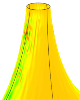
-
Dihedral analysis - Access Dihedral analysis by selecting the Show Analysis tools icon (
 ) at the bottom right corner of the interface. This displays the angle between the normals of 2 surfaces at a shared edge. If the angle is zero, the 2 surfaces are at least tangent at that location along the edge. In the example below, the dihedral intentionally changes from a hard crease to a smooth tangent blend at the other end of the curve:
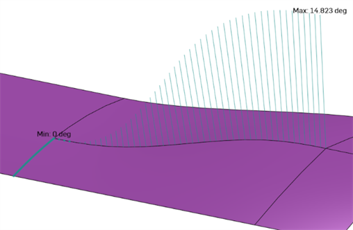
-
Deviation analysis - Display the minimum and maximum deviation between 2 curve chains in a Sketch or Part Studio, or 2 surfaces in a Part Studio.
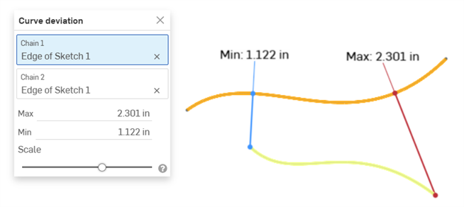
Example showing the Max/Min deviation between two curves
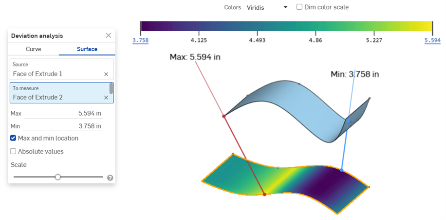
Example showing the Max/Min deviation between a "Source" surface and a surface "To measure"
See Deviation analysis for more information.
-
Reflection analysis - Renders the model in the graphics area with a reflective material and environment image of your preference.
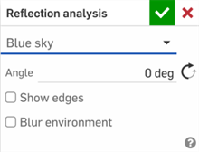
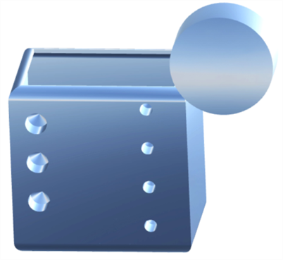
See Reflection analysis for more information.
-
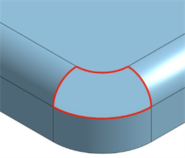
Highlight boundary edges - Highlight any open edges in red. Access Highlight boundary edges from the Camera and render options dropdown (
 ) below the View cube. This is useful when you are trying to identify any open areas in a surface to form a solid.
-
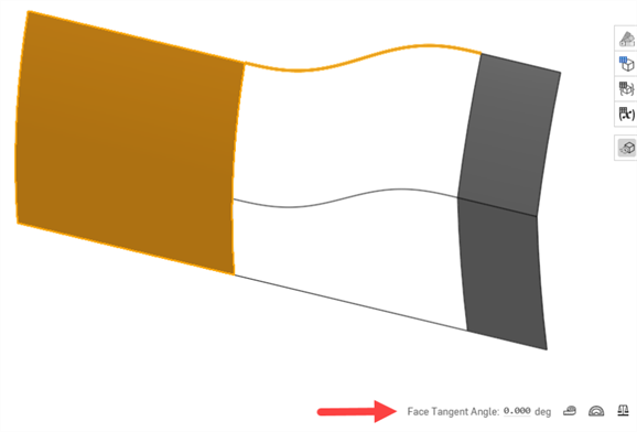
Face Tangent Angle - Face Tangent Angle (a Measure tool) provides quick feedback on whether a curve approaching a face is tangent at its endpoint. Select the face. The tangency angle is displayed to the left of the measure tool. This is useful to test continuity before completing a Loft or Boundary surface:
-
View in high quality - Turns on the highest available quality tessellation for the view and is essential to identify curve imperfections and evaluate continuity accurately. Access View in high quality from the Camera and render options dropdown (
 ) below the View cube.
 -
Shaded with edges/Tangent edges - Useful to view edge continuity more clearly. Access both these options from the Camera and render options dropdown (
 ) below the View cube.
-
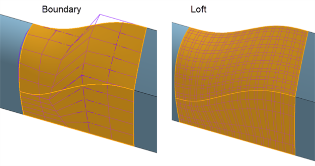
Boundary surface - Some features provide little control over the curves to create a surface, over-complicating and decreasing surface quality. A Boundary surface provides complete control over the U and V direction curves. The resultant surface is only as complicated as the input curves. Loft, Sweep, and Fill features create curves in one or both directions that cannot be controlled, complicating the surface.
For example, the same surface is built with a Boundary surface and a Sweep. The sweep develops curves along the V direction along the path, creating an overly complex surface:

The same surface is built with a Boundary surface and a Loft. The Loft creates a dense control point grid in both directions:
-
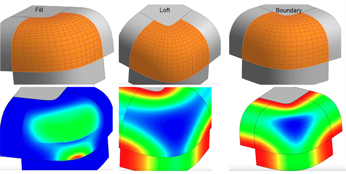
Fill - Fill patches small holes in a surface. After using Fill, evaluate the resultant surface to ensure a quality surface. In the example below, Fill adds a ripple towards the bottom. Loft creates a better control point grid with no rippling, but the Boundary surface creates the smoothest, most consistent result:
-
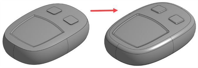
Face Blend and Fillet - Face blend and Fillet create complex edges similar to projections or split operations. Edges created by Face blend or Fillet have a higher chance of failing and introducing imperfections due to the complexity of these features. Since this is usually cosmetic, building the surfaces to the virtual sharps and adding these features at the end is best:
-
Use Beziers instead of Splines - Splines have points defined along the curve and handles on the start and end points. Beziers have control points defined along the control polygon offset from the curve. Bezier curves increases and decreases smoothly with no continuity breaks:

-
Keep curves simple - Use the Bezier tool and start with 3 or 4 control points (including endpoints). Add the least possible amount of Spline points.
-
The degree of a Bezier is the number of control points minus 1. Beziers should generally be of the degree 3, 5, or 7. Limiting the degree of a single Bezier curve to 7 is best because the mathematical computation becomes very complex at higher degrees. Moving one control point affects the entire curve, and higher-degree curves are difficult to adjust without introducing imperfections.
-
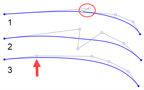
Use a consistent flow of control points to ensure smooth curvature changes with no unintended intensity changes.
Below are a few examples of curves with poorly placed control points. The first has a zig-zag between the first and second points (outlined by the circle). The second has control points positioned above and below the curve. It is only appropriate to change which side you place control points on when you intend to add inflection to the curve. The third does not have smooth spacing between control points. The point’s spacing compared with the others is drastically different (indicated by the arrow below):
-
-
Avoid building from trimmed edges or projected curves - Since these are made from trimming operations or projections with many spans (segments knotted together) of degree-3 (cubic) splines, anything built from them is more complex and imperfect.
For example, the surface here has a denser control point grid when creating a ruled surface directly from a trimmed surface's edge (below left). Instead, overbuild both surfaces and use a Mutual trim to trim the excess at the intersection (below right):
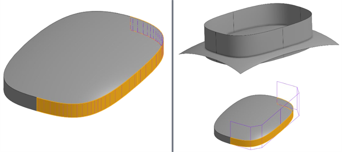
Instead of projected curves, see if Bridging curves can build the same geometry with less complexity. Bridging curves are Bezier curves that reach up to degree-5, depending on end conditions.
-
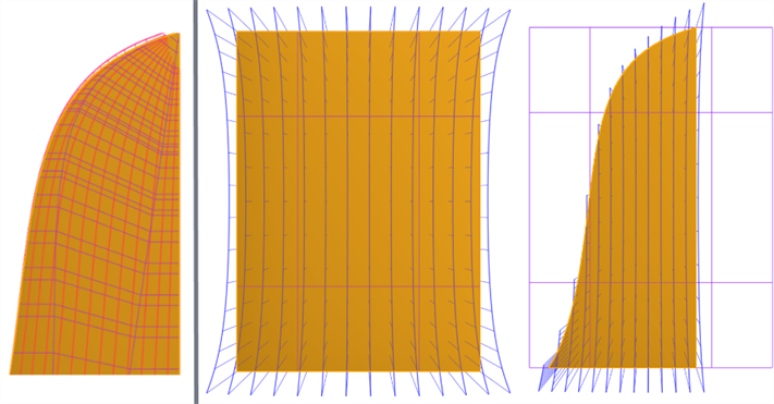
Aim to use four-sided surfaces - Four-sided surfaces have the most consistent control point grid. Creating a surface without four sides leads to singularities (degenerates) or irregularly spaced control points (shown below left). Overbuild and trim the surface with a reference surface using the Split feature. This creates surfaces with different edge profiles, while maintaining a consistent control point grid (shown below right):
-
Use symmetry when possible - Apply constraints for continuity to ensure a smooth transition across the centerline.
-
Use reference lines in a sketch with Tangent or Curvature constraints.
-
In a 3D model, add reference surfaces to assist with the continuity of the generated surface.
-
-
Use shortcut menus and hotkeys - Use shift+c (Curve/surface analysis), shift+d (Dihedral analysis), and shift+r (View in high quality). You can also customize the Shortcut toolbar (s) under My account > Preferences > Shortcut toolbars.
這個清單是曲面特徵工具的集合,並非詳盡的清單。在建構曲面時,可能會使用其他的特徵工具。詳細資訊請參考曲面建構。
-
 加厚 - 將厚度加入到曲面上。藉由給予曲面厚度然後將其轉換為實體,在現有零件或曲面上加入或移除材料,或是在路徑上使零件相交來建立新的零件或修改現有的零件。
 -
 封閉 - 選擇可形成實體的空間周圍的所有邊界來建立零件。使用任何互為相交或在邊界相接的曲面組與實體 (包括平面和面) 來建立一個體積。藉由加入或移除零件,或使零件相交來建立新的零件或修改現有的零件。
 -
 圓角 - 選擇「邊線」圓角來圓化尖銳的內部與外側邊線,並定義標準的固定半徑,建立更有造型的圓錐或變化。選擇性地套用「全周」圓角來在兩個對邊間建立一或多個面上無縫的混合。
 -
 面混合 - 圓滑化尖銳的連接或未連接的內部與外部面以建立面之間無縫的混合,或是將混合分離來建立新的面, 並可定義半徑或固定寬度。進一步定義混合的橫截面 (滾動球或掃出輪廓)、對稱、控制、修剪、約束與限制。
 -
 刪除面 - 從零件上移除一個幾何。選擇是否要修復周圍的面 (延伸面直至面相交),為空白加蓋,或將空白保留為開放。如果您沒有零件的參數式歷程記錄時 (通常在匯入的零件中有此狀況),此直接編輯的工具是相當方便的。
 -
 移動面 - 平移、旋轉或偏移一或多個所選的面。如果您沒有零件的參數式歷程記錄時 (通常在匯入的零件中有此狀況),此直接編輯的工具是相當方便的。
 -
 替換面 - 修剪一個面或將面延伸至一新的曲面。如果您沒有零件的參數式歷程記錄時 (通常在匯入的零件中有此狀況),此直接編輯的工具是相當方便的。
 -
 偏移曲面 - 偏移一個現有面、曲面或草圖區域來建立新的曲面。將偏移距離設定為 0 來就地產生一個副本。
 -
 邊界曲面 - 建立或新增由曲面邊界輪廓指定而來的曲面。
 -
 填補 - 定義邊界並使用邊界條件 (而不需使用參考曲面) 來細修曲面以建立一個曲面 (或從曲面建立零件)。
 -
 移動邊界 - 移動曲面的邊界線以延伸或修剪曲面。
 -
 直紋曲面 - 從一條現有邊線或草圖區域的多條邊線建立一個新的或額外的直紋曲面。
 -
 相互修剪 - 延伸兩個相鄰曲面的相交以完成對曲面的修剪。
 -
 約束曲面 - 從指定公差內的點或網格資料中選擇以建立曲面。顯示偏差並最佳化效能或平滑度。
除了曲面建構工具之外,還可使用曲線來建立曲面的基本建構塊。
這個清單是曲線特徵工具的集合,並非詳盡的清單。在操控曲線時,可能會使用其他的特徵工具。
- 草圖工具 - 草圖工具列中的工具,像是直線、轉角矩形、中心點矩形、中心點畫圓、三點畫圓、切線弧、三點定弧、樣條、點與建構線,可用來建立 Part Studio 中的草圖。
-
 螺旋線 - 使用圓錐或圓柱面、單一軸或結合連接器的 z 軸、或是環狀邊線來建立螺旋線。
 -
 3D 擬合樣條 - 建立穿過連續頂點的 3D 擬合樣條。建立列在零件清單中「曲線」之下的曲線。
 -
 投影曲線 - 建立一條來自兩個草圖投影的曲線 (「兩個草圖」選項),或是建立一條來自曲線投影至面的曲線 (「曲線到面」選項)。
 -
 橋接曲線 - 建立連接任兩個點、頂點或結合連接器的一條曲線。所產生的曲線會列於「特徵」清單與「零件」清單中。
 -
 複合曲線 - 以一條曲線來代表多條邊線。選擇多條相鄰的邊線、草圖圖元、與其他的曲線。選擇非連續的邊線會建立多條的曲線。為每條曲線做出的選擇項目必須在其頂點處交會 (曲線會列於「零件」>「曲線」清單之中)。
 -
 相交曲線 -在兩或多個曲面或面的相交處建立一條曲線。選取的項目必須是相交的。
 -
 修剪曲線 -根據距離修剪或延伸曲線,或是修剪或延伸至邊界圖元。
 -
 等傾線 - 在斜面上建立一條等傾線。等傾線會出現在面相較於其參考定義有某些傾斜的位置。所產生的等傾線會列於「特徵」清單與「零件」清單中。
 -
 偏移曲線 - 藉由在周圍面上偏移邊線來建立與延伸和/或分割新的曲線。
 -
 等參數曲線 - 建立沿面或曲面的 U 方向或 V 方向延伸的平滑曲線。
 -
 編輯曲線 - 選擇草圖圖元或曲線來套用簡化的近似、提高度數、重新定位控制曲線頂點和/或平化至任何 2D 平面來編輯現有的曲線。
 -
 路線曲線 - 建立在 3D 空間中跨越一個或多個平面的多點曲線 (路線路徑)。這對於建立管路路線、配線、以及進階曲面建立中的 NURBS 曲線是非常有用的。
For more surfacing resources, visit our Learning center.