![]()
![]()
![]()
選擇草圖圖元或曲線來套用簡化的近似、提高度數、重新定位控制曲線頂點和/或平化至任何 2D 平面來編輯現有的曲線或建立新的曲線。
「編輯曲線」可讓您在維持曲線與依賴曲線的下游特徵間關聯性的同時,編輯曲線。這可幫助更正建構模型依序進程中由先前不良曲線所造成的曲面。例如,如果疊層拉伸造成不良的曲面,編輯用做為疊層拉伸結果基礎的原始曲線可產生較佳的曲面。
使用「編輯曲線」特徵來:
-
改善匯入曲線的幾何以平滑化、順化、重建、重參數化、與近似曲線。
-
透過曲線的控制點編輯現有曲線的形狀。
-
參考其他幾何來定位曲線的一個控制點。例如,如果您的橫桿有數個替用大小的組態,然後您希望一個不同零件的曲線更新其與橫桿的對齊。
-
提高曲線的度數來與所需的度數相配,改善連接性,或對曲線的形狀有更精準的控制。
-
更正曲線中不要的扭轉/扭曲。曲線與其控制點會轉移至一所選的平面或結合連接器來拉ˋ直 (平面化) 曲線。
不論是用來當做複雜疊層拉伸和邊界曲面的導引曲線,或是做為掃出的路徑,曲線通常是用來提供做為複雜 3D 幾何的基礎 。有些時候可能需要調整這些曲線以符合所需的設計意圖。在這種案例中,Onshape 的「編輯曲線」特徵可允許在維持曲線與依賴曲線的下游特徵間關聯性的同時修改曲線。例如,曲線可能有會影響疊層拉伸特徵形狀的不良扭轉。編輯曲線來將扭轉平滑化以產生較平滑的疊層拉伸。
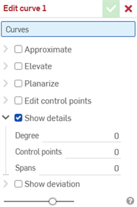
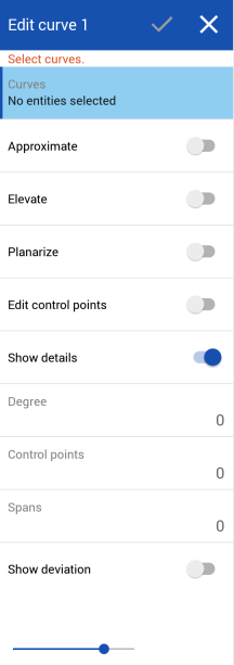
「編輯曲線」特徵提供重建曲線、重塑形曲線,以及從各種原生或匯入來源操作曲線的多個選項。
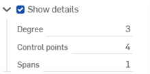
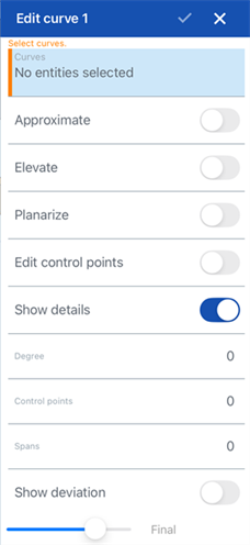
「編輯曲線」特徵同時可讓您顯示或隱藏度數、控制點數量與跨距數量這些唯讀的曲線ˋ值。
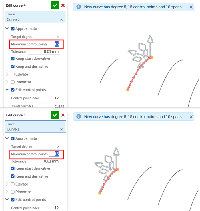
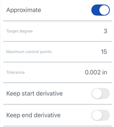
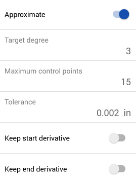
核取「近似」來重新近似曲線。這樣會將曲線重建為新的數學規格。設定「目標度數」、「最多控制點」數量與「公差」。核取「保持開始導數」與「保持結束導數」來保持在曲線兩端的曲線相切。
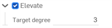
核取「提高」來為曲線提供一個新的目標度數。這個選項會將曲線提高至新的較高度數,因此增加控制點的數量,進而可對曲線的形狀有更精細的控制。
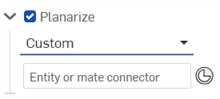
核取「平面化」來將曲線的控制點從其目前位置投影到一所選的參考平面上。有數個選項可決定 Onshape 投影控制點於其上的平面。「最佳擬合」會使用所有控制點的平均位置來將控制點投影到與曲線路徑最相符的平面上。核取「鎖定端點」來將曲線端點鎖定在其原始位置上。YZ、XZ、與 XY 平面會將控制點投影到個別的平面上。「自訂」會將控制點投影到所選平面或由結合連接器提供的平面上。選擇「結合連接器」圖示來啟用對隱含或明確結合連接器的選擇。
核取「編輯控制點」來修改在所選曲線上個別控制點的位置與權重。最開始的「控制點索引」是 0,對應於曲線上的第一個控制點。輸入控制點的索引數字或在圖形區域中選擇適當的控制點來選取其他的控制點。在選取了控制點之後,按一下「加入點置換」來手動輸入偏移與權重值,或使用三向操控器來在圖形區域中調整位置。根據預設,這些偏移是相對於原始控制點的位置,但是當您提供可選的參考時,可以從一特定點偏移控制點。「權重」決定控制點相對於曲線的權重。權重越大,曲線就越靠近控制點。權重會以您輸入的值乘出曲線上點的影響力。
對話方塊操作的順序有從上到下的層級 (從「近似」到「提高」再到「平面化」,最終是「編輯控制點」)。如果您要更改這個操作的順序,請建立多個「編輯曲線」特徵以根據您的需求依序修改順序。例如,建立一個編輯曲線控制點的「編輯曲線」特徵,然後再建立用來平面化同一曲線的第二個「編輯曲線」特徵。
您可以使用「近似」或「提高」來確定在每個曲線上的控制點數量是一樣的,以幫助對齊與平滑疊層拉伸的曲面。
當在圖形區域中至少有一個線性草圖圖元或曲線可用時:
- 按一下工具列中的「編輯曲線」特徵 (
 )。
)。
-
在圖形區域中選擇並未自相交錯的一或多個線性草圖圖元和/或曲線。草圖圖元或曲線必須依循連續的路徑,且如果選取了多條曲線,則必須重新近似曲線 (核取下方的近似),這樣會產生一條新的曲線。
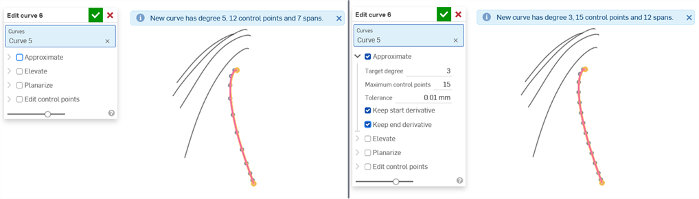
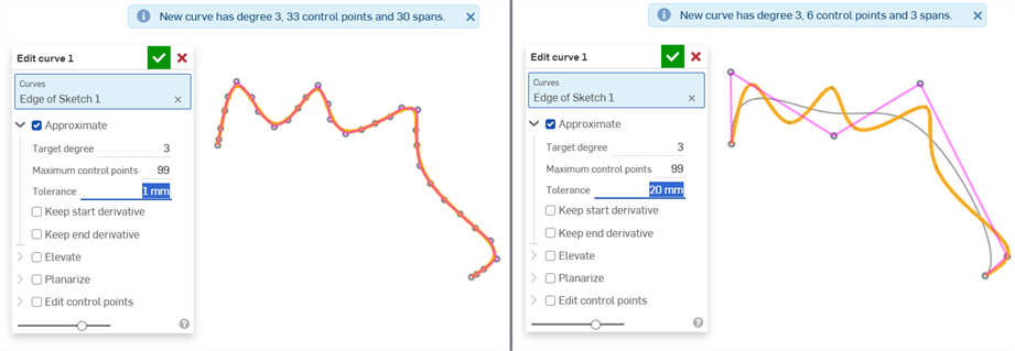
- 核取近似來開啟重新近似曲線的選項。會以橘色顯示原始的曲線,近似後的新曲線則以紫紅色顯示。「近似」會嘗試保持曲線的幾何,但並不保證可達成。
目標度數 - 輸入所選曲線的目標曲線度數。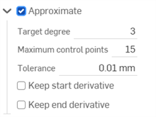
- 最多控制點 - 輸入所選曲線允許的最多控制點數量。
- 公差 - 所選曲線的公差,以長度測量。輸入公差值。
- 保持開始導數 - 核取來在所選曲線的起始處保持相切。
- 保持結束導數 - 核取來在所選曲線的結束處保持相切。
- 核取提高來開啟目標度數選項。如果需要,為所選曲線輸入較高的目標曲線度數。這對配對所需度數、改善連接性,或對曲線的形狀有更精準的控制是相當有用的。會保持曲線的幾何。
- 核取平面化來開啟沿一參考平面拉直曲線的選項。平面化會將控制曲線從其目前的位置投影到所選的參考平面上:
參考平面的選項有:
最佳擬合 - 沿與曲線路徑最相符的平面投影曲線 (使用所有控制點位置的平均)。
鎖定端點 - 核取來確保曲線的端點是固定且無法移動的。這對於保持附加幾何的連續性是相當有用的。
YZ 平面 - 沿 YZ 平面投影曲線 (垂直於 X 軸)。
XZ 平面 - 沿 XZ 平面投影曲線 (垂直於 Y 軸)。
XY 平面 - 沿 XY 平面投影曲線 (垂直於 Z 軸)。
自訂 - 沿一自訂平面或隱含或明確結合連接器的 XY 軸投影曲線 (垂直於其 Z 軸)。
- 核取編輯控制點來開啟加入參考,以及在所選曲線上修改個別控制點位置與權重的選項:
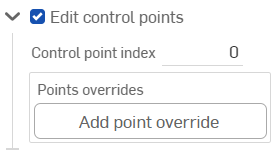
在核取「編輯控制點」之後,在圖形區域中會有三向操控器出現,其原點是放置在第一個控制點上 (控制點索引 0)。
這個控制點索引欄位是在曲線的點索引/ID 的最上方,並從 0 開始。您可以在這個欄位中輸入索引數字來選擇每個控制點。當您操作時,三向操控器會圖形區域中移動至相對應的控制點上。
三向操控器調整:
跨三個軸的平移
跨三個平面的平移。
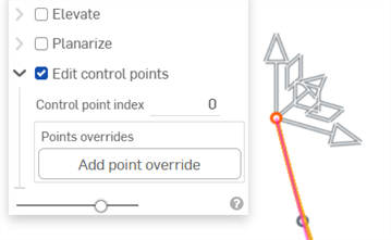
按一下 加入點置換 按鈕或調整三向操控器來為目前所選的點加入置換的選項:
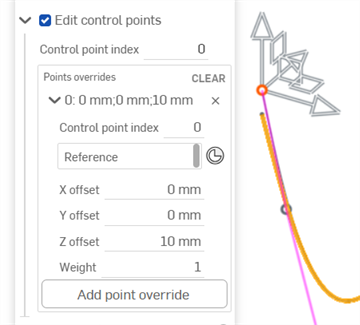
將 Z 軸操控器調整為 10 mm 開啟了目前控制點 (上圖中索引 0) 的選項。
您可以為曲線上的每個控制點個別加入置換的設定。按一下 加入點置換 按鈕來為其他的點加入自訂的置換設定。在每個點上只能套用一組的置換設定。
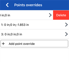
按下列左邊的插入符號 (
 ) 來展開/摺疊每個列/控制點的置換。每個點的置換會列出索引數字,接著會有 X/Y/Z 偏移值。按一下每列右側的 x 來清除該點的置換。按一下表格右上角的 [清除] 來清除所有列/控制點的置換設定。
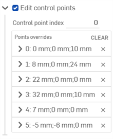
如果需要,編輯下列各個控制點置換選項:
- 控制點索引 - 這是要置換的控制點的索引。選擇曲線上點的索引/ID。索引是從 0 開始。
在這個階層切換控制點索引會將目前所有點置換的設定套用到該控制點上。這樣您可以立即將置換設定從一個控制點轉移到另一個控制點上。
為曲線上的每個控制點編輯下列的置換設定:
- 參考 - 預設參考是未變更的控制點位置 (三向操控器的原點)。選擇一個頂點、草圖點、或是明確或隱含的結合連接器來做為相對於這個點的目前點的 X/Y/Z 偏移值。
當編輯控制點時,若要建立一個隱含的結合連接器,按一下選擇結合連接器圖示 (
 ),然後在模型中您要建立結合連接器的位置上按一下。現在即會使用這個結合連接器來做為點參考。
 - X/Y/Z 偏移 - 顯示控制點從其參考偏移的目前位置。如果需要,請在每個欄位中輸入偏移數值。
- 權重 - 決定控制點相對於曲線的權重。較高的權重值會將曲線〝拉近〞控制點。輸入權重值,系統會用該值乘出曲線上點的影響力。
- 參考 - 預設參考是未變更的控制點位置 (三向操控器的原點)。選擇一個頂點、草圖點、或是明確或隱含的結合連接器來做為相對於這個點的目前點的 X/Y/Z 偏移值。
- 加入點置換 - 加入新的點置換到表格中,可以使用目前所選索引的索引,或是在陣列中目前索引後第一個未使用的索引 (如果已使用目前的索引)。
- (選用) 根據預設,顯示詳細資料是啟用的,且會提供度數值、控制點數量、與跨距數量的唯讀資料。取消核取這個選項來隱藏這些詳細資料。
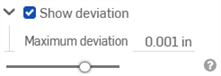
- (選用) 如果已重新近似曲線,您可以啟用顯示偏差核取方塊來檢視原始曲線與重新近似後曲線間的最大偏差。
- 按一下核取記號 (
 ) 以接受「編輯曲線」特徵。
-
原始曲線 (左圖) 與使用「近似」之後的曲線 (右圖):
-
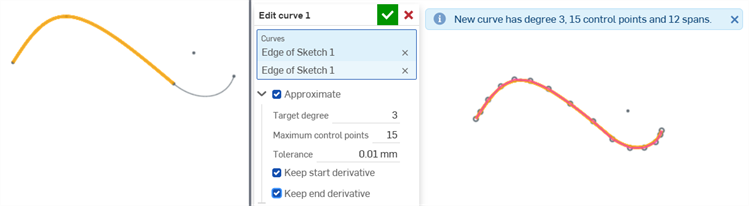
從 2 個相切的草圖圖元建立一條新曲線 (左圖);使用「近似」之後,草圖圖元結合為一條單一曲線 (右圖)。仍保留原始的草圖圖元,可供其他目的使用。
-
使用「公差」選項來平滑曲線:
-
提高以與目標度數相符:
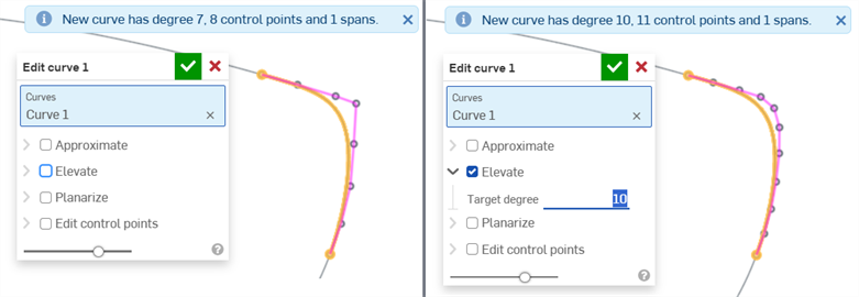
沒有任何提高 (左圖) 與提高至 10 的「目標度數」(右圖)
-
平面化以沿平面拉直曲線:
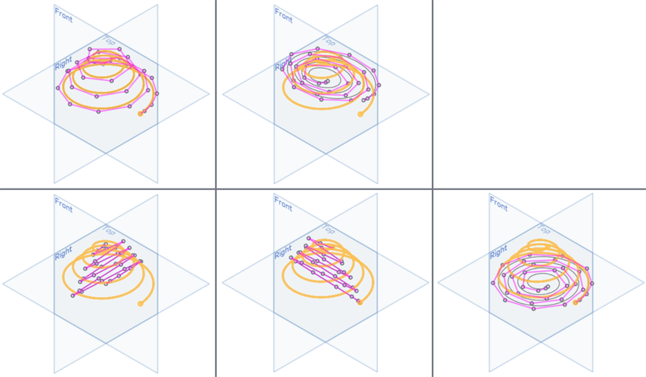
上圖:未核取「平面化」(左圖)、「最佳擬合」(右圖);下圖由左至右:YZ 平面、XZ 平面、XY 平面
-
將螺旋線平面化為螺旋形:
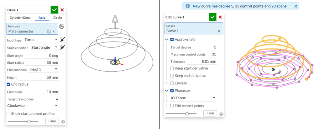
螺旋線特徵 (左圖),使用「編輯曲線」>「平面化」將螺旋線平化為螺旋形 (右圖)
-
使用「自訂」選項,然後選擇結合連接器做為平面基礎的平面化:
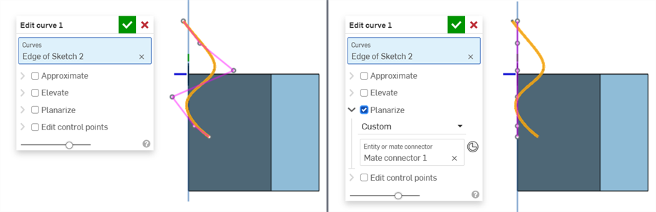
未核取 (左圖) 與核取 (右圖) 「平面化」。選取了「自訂」並使用結合連接器做為自訂平面。
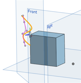
在與其他平面的關聯中顯示使用自訂結合連接器平面來平化的與上方相同的曲線:
-
編輯沿曲線的控制點來細調曲線的形狀:
沒有編輯任何點的原始曲線 (左圖),編輯點 2 與 4 所建立的較平滑曲線 (右圖)
-
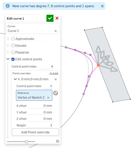
編輯一個控制點來參考現有的幾何 (對於曲線的外部幾何)。使用這個方法時,如果參考的幾何變更,則曲線會根據該幾何調整。例如,如果參考幾何有數個不同的大小,並將這些大小設定為組態,則不論選取的組態為何,曲線永遠會依循幾何。
在匯入 CAD 之後,您可能會有不良的曲線。如果您使用不良的曲線進行許多模型建構的操作,可能會讓問題更嚴重,甚至有可能到設計後期才發現問題。
此處是已匯入 CAD 資料的範例 (匯入的是用於船體的曲線)。使用曲線/曲面分析工具,您可以看到下列曲線的問題:
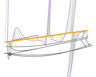
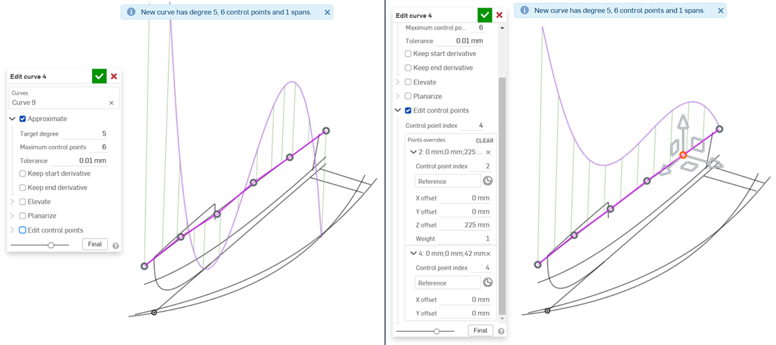
曲面是由這條曲線建立而來,結構不良曲線中的資料會在設計過程中傳遞至下游。編輯曲線 (下方中第一個圖片) 可產生較平滑的曲線 (下方中第二個圖片)。您可以在匯入的過程ˊ之後直接編輯曲線,所有依賴該曲線的下游特徵都會自動更新:
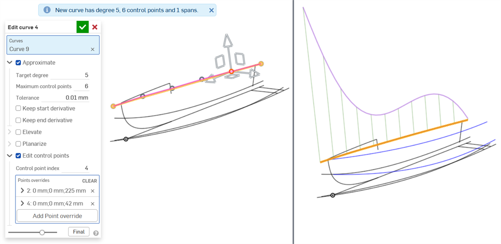
近似曲線到「目標度數」:5;「最多控制點」:6,然後編輯控制點來建立平滑的曲線。
下方顯示使用下游特徵 (來自之前曲線) 所產生的結果邊界曲面的品質差異:
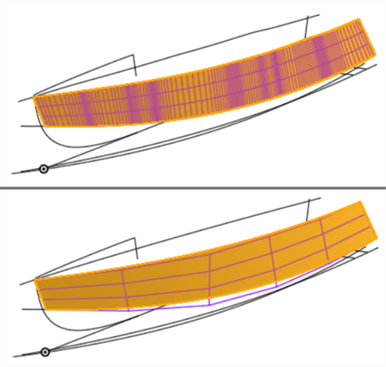
由曲線建立的邊界曲面有問題 (上圖),在編輯曲線之後會有較佳品質的曲面 (下圖)。在曲線上較少的控制點會產生較平滑的曲面。
-
當套用「編輯曲線」的選項到曲線上時,會有層級的順序或操作 (相依性的順序)。會先套用近似,接著是提高,然後是平面化,最後則是編輯控制點。如果您要先為曲線編輯控制點,下一步接著平面化,您可以先後建立兩個「編輯曲線」特徵來達成此目的。在第一個「編輯曲線」特徵中編輯曲線的控制點,然後在第二個「編輯曲線」特徵中平面化曲線。
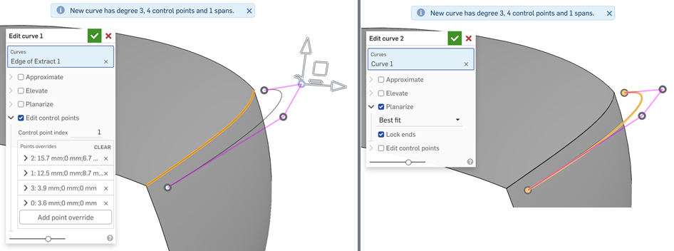
在第一個「編輯曲線」特徵中編輯曲線的控制點 (左圖),然後在第二個「編輯曲線」特徵中平面化曲線 (右圖) 來反轉在曲線上執行操作的順序
-
當編輯做為疊層拉伸 (最終會建立一個曲面) 基礎的多條曲線時,請確定在每條曲線上有相同數量的控制點。這樣可確保每條曲線上的點之間存在平行性,進而建立定義良好的疊層拉伸。
選擇草圖圖元或曲線來套用簡化的近似、提高度數、重新定位控制曲線頂點和/或平化至任何 2D 平面來編輯現有的曲線或建立新的曲線。
步驟
當在圖形區域中至少有一個線性草圖圖元或曲線可用時:
-
輕觸「編輯曲線」工具圖示 (
)。
-
在圖形區域中選擇並未自相交錯的一或多個線性草圖圖元和/或曲線。草圖圖元或曲線必須依循連續的路徑,且如果選取了多條曲線,則必須重新近似曲線 (核取下方的近似),這樣會產生一條新的曲線。
-
輕觸近似旁的切換來開啟重新近似曲線的選項。會以橘色顯示原始的曲線,近似後的新曲線則以紫紅色顯示。「近似」會嘗試保持曲線的幾何,但並不保證可達成。
-
目標度數 - 輸入所選曲線的目標曲線度數。
-
最多控制點 - 輸入所選曲線允許的最多控制點數量。
-
公差 - 所選曲線的公差,以長度測量。輸入公差值。
-
保持開始導數 - 切換開啟來在所選曲線的起始處保持相切。
-
保持結束導數 - 切換開啟來在所選曲線的結束處保持相切。
-
-
輕觸提高旁的切換來開啟「目標度數」選項。如果需要,為所選曲線輸入較高的目標曲線度數。這對配對所需度數、改善連接性,或對曲線的形狀有更精準的控制是相當有用的。會保持曲線的幾何。
-
輕觸平面化旁的切換來開啟沿一參考平面拉直曲線的選項。平面化會將控制曲線從其目前的位置投影到所選的參考平面上。
參考平面的選項有:
-
最佳擬合 - 沿與曲線路徑最相符的平面投影曲線 (使用所有控制點位置的平均)。
-
鎖定端點 - 切換開啟來確保曲線的端點是固定且無法移動的。這對於保持附加幾何的連續性是相當有用的。
-
YZ 平面 - 沿 YZ 平面投影曲線 (垂直於 X 軸)。
-
XZ 平面 - 沿 XZ 平面投影曲線 (垂直於 Y 軸)。
-
XY 平面 - 沿 XY 平面投影曲線 (垂直於 Z 軸)。
-
自訂 - 沿一自訂平面或隱含或明確結合連接器的 XY 軸投影曲線 (垂直於其 Z 軸)。
-
-
輕觸編輯控制點來開啟加入參考,以及在所選曲線上修改個別控制點位置與權重的選項。
在切換開啟編輯控制點之後,在圖形區域中會有三向操控器出現,其原點是放置在第一個控制點上 (控制點索引 0)。
這個控制點索引欄位是在曲線的點索引/ID 的最上方,並從 0 開始。您可以在這個欄位中輸入索引數字來選擇每個控制點。當您操作時,三向操控器會圖形區域中移動至相對應的控制點上。
您可以為曲線上的每個控制點個別加入置換的設定。輕觸加入點置換按鈕 (在對話方塊中點置換的部分) 來將自訂的置換設定加入到其他點上。在每個點上只能套用一組的置換設定。選擇加入點置換選項或調整三向操控器來為目前所選的點加入置換的選項。
按下列左邊的插入符號 (
) 來展開或摺疊每個列/控制點的置換。每個點的置換會列出索引數字,接著會有 X/Y/Z 偏移值。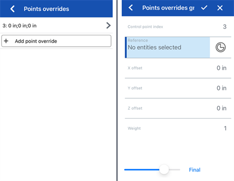
向左滑動並輕觸刪除按鈕來清除點的置換:
如果需要,編輯下列各個控制點置換選項:
-
控制點索引 - 這是要被置換的控制點的索引。選擇曲線上點的索引/ID。索引是從 0 開始。
在這個階層切換控制點索引會將目前所有點置換的設定套用到該控制點上。這樣您可以立即將置換設定從一個控制點轉移到另一個控制點上。
為曲線上的每個控制點編輯下列的置換設定:
-
參考 - 預設參考是未變更的控制點位置 (三向操控器的原點)。選擇一個頂點、草圖點、或是明確或隱含的結合連接器來做為相對於這個點的目前點的 X/Y/Z 偏移值。
當編輯控制點時,若要建立一個隱含的結合連接器,輕觸「選擇結合連接器」圖示,然後在模型中您要建立結合連接器的位置上輕觸。現在即會使用這個結合連接器來做為點參考。
-
X/Y/Z 偏移 - 顯示控制點從其參考偏移的目前位置。如果需要,請在每個欄位中輸入偏移數值。
-
權重 - 決定控制點相對於曲線的權重。較高的權重值會將曲線拉近控制點。輸入權重值,系統會用該值乘出曲線上點的影響力。
-
-
加入點置換 - 加入新的點置換到表格中,可以使用目前所選索引的索引,或是在陣列中目前索引後第一個未使用的索引 (如果已使用目前的索引)。
-
-
(選用) 根據預設,顯示詳細資料是啟用的,且會提供度數值、控制點數量、與跨距數量的唯讀資料。切換關閉這個選項來隱藏這些詳細資料。
-
(選用) 如果已重新近似曲線,您可以切換顯示偏差選項來檢視原始曲線與重新近似後曲線間的最大偏差。
-
輕觸對話方塊上方的核取記號來接受編輯後的曲線並關閉對話方塊。
選擇草圖圖元或曲線來套用簡化的近似、提高度數、重新定位控制曲線頂點和/或平化至任何 2D 平面來編輯現有的曲線或建立新的曲線。
步驟
當在圖形區域中至少有一個線性草圖圖元或曲線可用時:
-
輕觸「編輯曲線」工具圖示 (
)。
-
在圖形區域中選擇並未自相交錯的一或多個線性草圖圖元和/或曲線。草圖圖元或曲線必須依循連續的路徑,且如果選取了多條曲線,則必須重新近似曲線 (核取下方的近似),這樣會產生一條新的曲線。
-
輕觸近似旁的切換來開啟重新近似曲線的選項。會以橘色顯示原始的曲線,近似後的新曲線則以紫紅色顯示。「近似」會嘗試保持曲線的幾何,但並不保證可達成。
-
目標度數 - 輸入所選曲線的目標曲線度數。
-
最多控制點 - 輸入所選曲線允許的最多控制點數量。
-
公差 - 所選曲線的公差,以長度測量。輸入公差值。
-
保持開始導數 - 切換開啟來在所選曲線的起始處保持相切。
-
保持結束導數 - 切換開啟來在所選曲線的結束處保持相切。
-
-
輕觸提高旁的切換來開啟「目標度數」選項。如果需要,為所選曲線輸入較高的目標曲線度數。這對配對所需度數、改善連接性,或對曲線的形狀有更精準的控制是相當有用的。會保持曲線的幾何。
-
輕觸平面化旁的切換來開啟沿一參考平面拉直曲線的選項。平面化會將控制曲線從其目前的位置投影到所選的參考平面上。
參考平面的選項有:
-
最佳擬合 - 沿與曲線路徑最相符的平面投影曲線 (使用所有控制點位置的平均)。
-
鎖定端點 - 切換開啟來確保曲線的端點是固定且無法移動的。這對於保持附加幾何的連續性是相當有用的。
-
YZ 平面 - 沿 YZ 平面投影曲線 (垂直於 X 軸)。
-
XZ 平面 - 沿 XZ 平面投影曲線 (垂直於 Y 軸)。
-
XY 平面 - 沿 XY 平面投影曲線 (垂直於 Z 軸)。
-
自訂 - 沿一自訂平面或隱含或明確結合連接器的 XY 軸投影曲線 (垂直於其 Z 軸)。
-
-
輕觸編輯控制點來開啟加入參考,以及在所選曲線上修改個別控制點位置與權重的選項。
在切換開啟編輯控制點之後,在圖形區域中會有三向操控器出現,其原點是放置在第一個控制點上 (控制點索引 0)。
這個控制點索引欄位是在曲線的點索引/ID 的最上方,並從 0 開始。您可以在這個欄位中輸入索引數字來選擇每個控制點。當您操作時,三向操控器會圖形區域中移動至相對應的控制點上。
您可以為曲線上的每個控制點個別加入置換的設定。輕觸加入點置換按鈕 (在對話方塊中點置換的部分) 來將自訂的置換設定加入到其他點上。在每個點上只能套用一組的置換設定。選擇加入點置換選項或調整三向操控器來為目前所選的點加入置換的選項。
按下列左邊的插入符號 (
) 來展開或摺疊每個列/控制點的置換。每個點的置換會列出索引數字,接著會有 X/Y/Z 偏移值。輕觸每個列右邊的紅色 x 來清除該點的置換。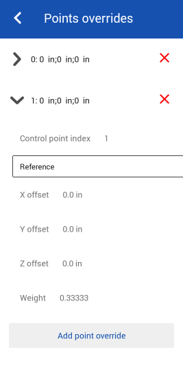
如果需要,編輯下列各個控制點置換選項:
-
控制點索引 - 這是要被置換的控制點的索引。選擇曲線上點的索引/ID。索引是從 0 開始。
在這個階層切換控制點索引會將目前所有點置換的設定套用到該控制點上。這樣您可以立即將置換設定從一個控制點轉移到另一個控制點上。
為曲線上的每個控制點編輯下列的置換設定:
-
參考 - 預設參考是未變更的控制點位置 (三向操控器的原點)。選擇一個頂點、草圖點、或是明確或隱含的結合連接器來做為相對於這個點的目前點的 X/Y/Z 偏移值。
當編輯控制點時,若要建立一個隱含的結合連接器,輕觸「選擇結合連接器」圖示,然後在模型中您要建立結合連接器的位置上輕觸。現在即會使用這個結合連接器來做為點參考。
-
X/Y/Z 偏移 - 顯示控制點從其參考偏移的目前位置。如果需要,請在每個欄位中輸入偏移數值。
-
權重 - 決定控制點相對於曲線的權重。較高的權重值會將曲線拉近控制點。輸入權重值,系統會用該值乘出曲線上點的影響力。
-
-
加入點置換 - 加入新的點置換到表格中,可以使用目前所選索引的索引,或是在陣列中目前索引後第一個未使用的索引 (如果已使用目前的索引)。
-
-
(選用) 根據預設,顯示詳細資料是啟用的,且會提供度數值、控制點數量、與跨距數量的唯讀資料。切換關閉這個選項來隱藏這些詳細資料。
-
(選用) 如果已重新近似曲線,您可以切換顯示偏差選項來檢視原始曲線與重新近似後曲線間的最大偏差。
-
輕觸對話方塊上方的核取記號來接受編輯後的曲線並關閉對話方塊。
除了曲面建構工具之外,還可使用曲線來建立曲面的基本建構塊。
這個清單是曲線特徵工具的集合,並非詳盡的清單。在操控曲線時,可能會使用其他的特徵工具。
- 草圖工具 - 草圖工具列中的工具,像是直線、轉角矩形、中心點矩形、中心點畫圓、三點畫圓、切線弧、三點定弧、樣條、點與建構線,可用來建立 Part Studio 中的草圖。
-
 螺旋線 - 使用圓錐或圓柱面、單一軸或結合連接器的 z 軸、或是環狀邊線來建立螺旋線。
 -
 3D 擬合樣條 - 建立穿過連續頂點的 3D 擬合樣條。建立列在零件清單中「曲線」之下的曲線。
 -
 投影曲線 - 建立一條來自兩個草圖投影的曲線 (「兩個草圖」選項),或是建立一條來自曲線投影至面的曲線 (「曲線到面」選項)。
 -
 橋接曲線 - 建立連接任兩個點、頂點或結合連接器的一條曲線。所產生的曲線會列於「特徵」清單與「零件」清單中。
 -
 複合曲線 - 以一條曲線來代表多條邊線。選擇多條相鄰的邊線、草圖圖元、與其他的曲線。選擇非連續的邊線會建立多條的曲線。為每條曲線做出的選擇項目必須在其頂點處交會 (曲線會列於「零件」>「曲線」清單之中)。
 -
 相交曲線 -在兩或多個曲面或面的相交處建立一條曲線。選取的項目必須是相交的。
 -
 修剪曲線 -根據距離修剪或延伸曲線,或是修剪或延伸至邊界圖元。
 -
 等傾線 - 在斜面上建立一條等傾線。等傾線會出現在面相較於其參考定義有某些傾斜的位置。所產生的等傾線會列於「特徵」清單與「零件」清單中。
 -
 偏移曲線 - 藉由在周圍面上偏移邊線來建立與延伸和/或分割新的曲線。
 -
 等參數曲線 - 建立沿面或曲面的 U 方向或 V 方向延伸的平滑曲線。
 -
編輯曲線 - 選擇草圖圖元或曲線來套用簡化的近似、提高度數、重新定位控制曲線頂點和/或平化至任何 2D 平面來編輯現有的曲線。
-
 路線曲線 - 建立在 3D 空間中跨越一個或多個平面的多點曲線 (路線路徑)。這對於建立管路路線、配線、以及進階曲面建立中的 NURBS 曲線是非常有用的。