 分析工具
分析工具
![]()
分析工具是用來在 Part Studio 中檢查草圖邊線/曲面與零件邊線/曲面/體積,並與在組合件中檢查實例曲面/干涉的設計整體性。分析工具圖示會出現在 Part Studio 與組合件界面的右下角。
按一下顯示分析工具 (![]() ) 來開啟環境選單:
) 來開啟環境選單:
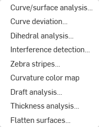
對於所有的分析工具,當重新開啟對話方塊時之前在工具對話方塊中做出的選擇可以是非持久或持久的,這是取決於存取工具對話方塊的方式。從分析工具功能表 (![]() ) 中選擇工具時會開啟其中沒有任何先前選取項目 (或持久) 的相對應對話方塊。使用工具的快速鍵則會開啟保留有先前輸入選取項目 (持久) 的工具對話方塊。透過這種方式,使用者可以決定保留或放棄先前對話方塊中的選取項目。關於如何為沒有快速鍵的工具指派快速鍵的資訊,請參考鍵盤快速鍵與熱鍵。
) 中選擇工具時會開啟其中沒有任何先前選取項目 (或持久) 的相對應對話方塊。使用工具的快速鍵則會開啟保留有先前輸入選取項目 (持久) 的工具對話方塊。透過這種方式,使用者可以決定保留或放棄先前對話方塊中的選取項目。關於如何為沒有快速鍵的工具指派快速鍵的資訊,請參考鍵盤快速鍵與熱鍵。
快速鍵:shift+c
在 Part Studio 中使用不同的方法視覺檢視與分析草圖或零件上的曲率。透過快速鍵 (Shift+c)、草圖、零件或曲面上的環境選單,或透過介面右下角的「顯示分析工具」功能表來存取「曲線/曲面分析」對話方塊。
當在草圖模式中或是在編輯草圖時,您可以使用快速鍵 Shift+c 來自動選取所有草圖曲線並開啟「曲線/曲面分析」對話方塊。Shift+c 如同切換鍵:當選取項目持續存在時可開啟與關閉對話方塊。
即使在退出草圖之後,曲線/曲面分析工具仍會保持為開啟,不過選取項目欄位並不是使用中。只要工具是開啟的,您可以加入更多選取項目或是移除項目。您下一次叫用工具時對選取項目的變更仍會存在。如果您在開啟工具之前已經做出預選,則開啟工具時會僅有該選取項目,系統會清除之前做出的其他選擇。
檢查曲線與曲面:
- 按一下介面右下角的「顯示分析工具」 (
 )。
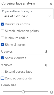
)。 - 選擇曲線/曲面分析來開啟對話方塊。您也可以在圖形區域中於草圖或零件上按右鍵,然後從環境選單中選擇來存取這個對話方塊:
-
選擇要分析的邊線和面,或者是在存取對話方塊之前先選擇邊線和面。
- 從下列的選項中選擇:
曲率梳 - 沿著 U 和 V 方向顯示所選邊線和/或面的梳形。曲率梳是在平均間隔的等值線上評估的,並不一定是在控制點上,是用來評估求出多至流動 (G3) 連續性的曲面/曲線生成的形狀。
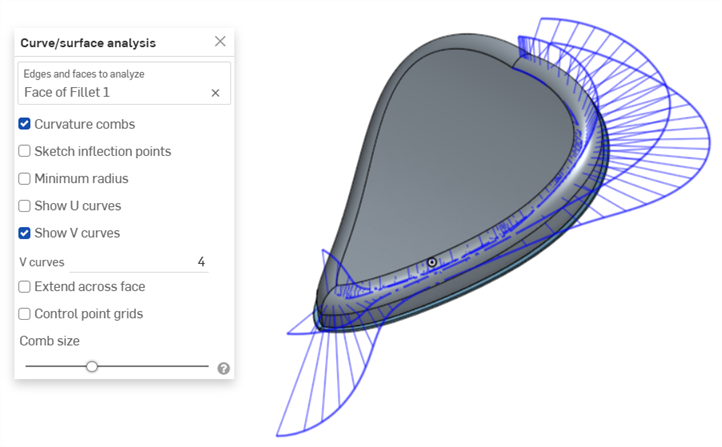
在面 V 方向上的曲率梳
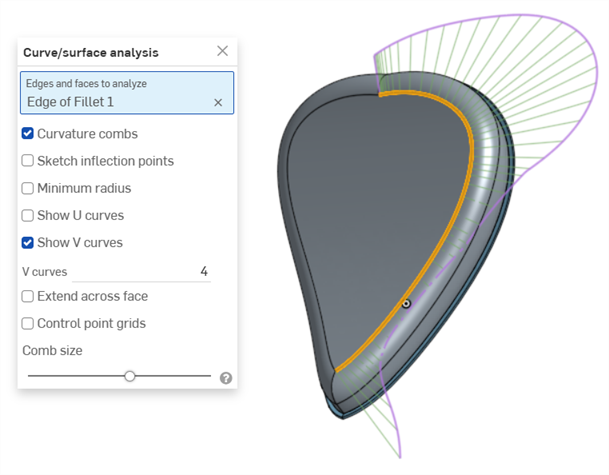
在邊線上的曲率梳。以綠色顯示梳形,紫紅色顯示邊界。
Show U curves - Displays curvature combs along the U direction. U curves are displayed in red:
Show V curves - Displays curvature combs along the V direction. V curves are displayed in blue:
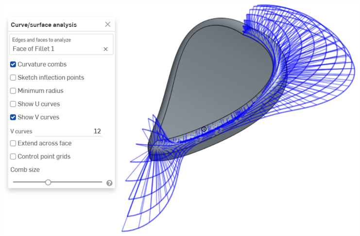
Increase or decrease the number of curves using the numeric U curves and V curves fields, from 2 to 64. The default is 8 for each.

V 曲線設定為 2 (左圖)、4 (中間圖)、與 8 (右圖)
Sketch inflection points (sketch only) - Displays the inflection points along a sketch edge. They appear as black 'bow ties':
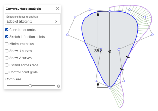
Minimum radius (edges only) - Shows the minimum radius along an edge, either a sketch or part edge:
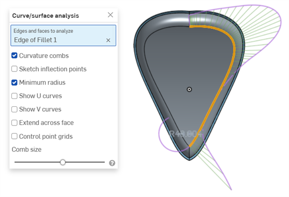
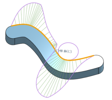
跨面延伸 - 沿相鄰面延伸曲率梳:
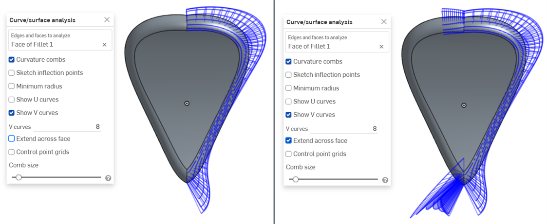
曲率梳未延伸跨面 (左圖),曲率梳延伸跨面 (右圖)
控制點網格 - 顯示在所選邊線 (可以草圖或是零件邊線) 上的控制點網格。這是定義曲面 (或曲線) 的下方 bSpline 曲線上控制點的位置。控制點的數量與分布提供關於定義形狀的數學重要資訊。
密集群聚的控制點表明了潛在的問題區域,對曲面品質可能會是有害的。簡而言之,控制點網格是用來了解曲面/曲線之下的數學定義的。
以紫紅色顯示的控制點網格:
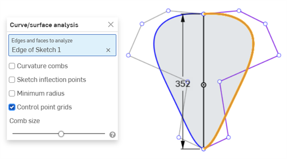
以紫紅色顯示的控制點網格
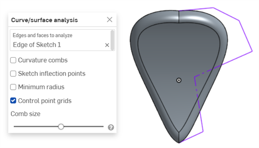
關閉草圖並顯示零件時顯示的控制點網格
Knot points - Displays the knot points on the selected curve or surface. (Not available for non-spline entities such as cylindrical faces, intersection curves, offset curves, etc.)
Details - Displays details (such as degree, spans, and number of control points) upon hovering over the selected curve or surface. (Not available for non-spline entities such as cylindrical faces, intersection curves, offset curves, etc.)
Comb size - Use the slider at the bottom of the dialog to adjust the magnitude of the combs.
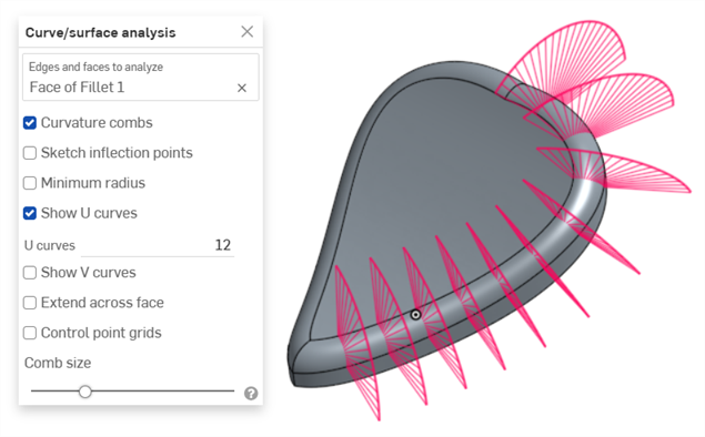
-
如果需要,點按與拖曳曲線來調整曲率。會在拖曳的過程中動態更新曲率梳。
-
完成時按一下
 來關閉「曲線/曲面分析」對話方塊。
在建立特徵的過程中顯示曲率
您也可以顯示處理中特徵的曲率梳。例如,在擠出的過程中:
- 在特徵對話方塊開啟的同時,在圖形區域中按右鍵,然後選擇 [曲線/曲面分析] 來開啟「曲線/曲面分析」對話方塊:

- 選擇特徵上的曲線:
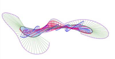
- 您可以顯示用來建立新特徵的所選邊線曲率 (取消核取 [顯示預覽邊線]),或選擇顯示預覽邊線來查看新特徵建立邊線的曲率梳:
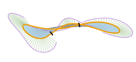
您也可以選取「顯示曲率」對話方塊中選項左側的核取方塊來顯示曲率梳、拐點與最小半徑。
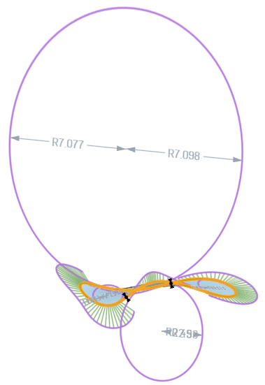
在「顯示曲率」對話方塊中選取「顯示預覽邊線」、「顯示曲率梳」、「顯示拐點」與「顯示最小半徑」時特徵的範例。
關於曲率與曲面分析的詳細資訊,請參考曲面模型建構。
可以在草圖或 Part Studio 中顯示 2 條連續曲線間的最小與最大偏差。
-
在 Part Studio 中按一下介面右下角的「顯示分析工具」(
 ) 。
) 。 -
從功能表中選擇曲線偏差來開啟對話方塊:
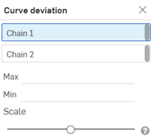
-
在對話方塊中選取了連續 1 的情況下,於圖形區域中選擇一或多條相鄰的曲線。
-
在對話方塊中選取連續 2,然後於圖形區域中選擇一或多條相鄰的曲線。
圖形區域中會顯示最小 (藍色) 與最大 (紅色) 偏差,並會有相對應的極端值點:
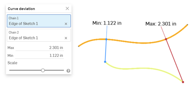
顯示兩條曲線間最小/最大偏差的範例。
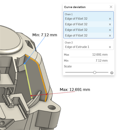
顯示在圓角 (連續 1) 中連續曲線與擠出曲線 (連續 2) 間最小/最大曲線偏差的範例。
-
選擇性地調整比例滑桿來在圖形區域中移動最小與最大的測量標籤。將滑桿向左移動會將標籤移動靠近所選的曲線。將滑桿向右移動會將標籤移動遠離所選的曲線。
偏差計算
如果所選的連續有重合端點,會根據兩個連續的全長來計算偏差。
如果所選的連續沒有重合端點,則所選連續的端點會根據其間的較小最小距離值來配對。
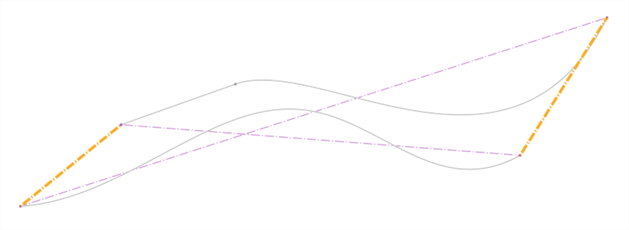
曲線偏差的計算如下:
-
對於每個端點配對組:
-
會計算每個端點到另一連續的最小距離。
-
會使用最低最小距離值的相交點來修剪偏差計算的範圍。
-
會為該範圍計算最大與最小的偏差。
-
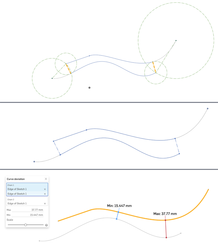
3 個圖片顯示的是同一曲線組。最上方的圖片中以鮮橘色顯示最小距離。可以在第二個圖片中清楚地看到經修剪的曲線 (右端的上方曲線和左端的下方曲線)。最下方的圖片顯示為上方兩個圖片中所示範圍計算出來的最大與最小偏差。
注意
-
為每個連續所選的曲線必須是連續的。
-
如果連續之間的多個極值點有相同的最大或最小偏差值,則僅會顯示一個。
-
如果您剛好就選擇 2 條曲線,接著開啟「曲線偏差」對話方塊,則會將第一條所選曲線自動放置在連續 1 欄位中,第二條選取的曲線則會放置在連續 2 欄位中,系統會自動計算兩條曲線間的最小/最大偏差。
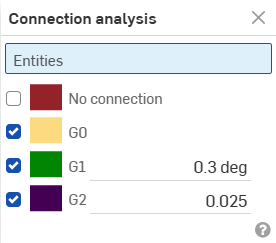
Assess or report the connection between curves and surfaces in a Part Studio or Sketch. Select two curves (or an edge adjacent to two faces) to analyze if the connection meets G0, G1, and/or G2 tolerances.
-
In a Part Studio, click the Show analysis tools icon (
 ) in the bottom right corner of the interface.
 -
From the menu, select Connection analysis to open the dialog box:
-
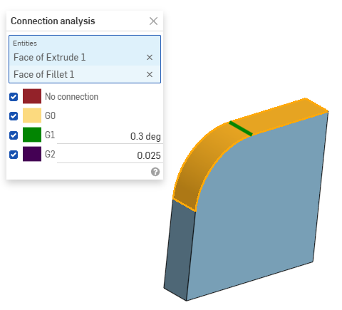
Select curves or surfaces to analyze; the dialog box populates with results automatically upon selection, along with color coordinated indicators in the graphics area:
快速鍵:shift+d
在 Part Studio 中顯示所選邊線的二面角度。
當在草圖模式中或是在編輯草圖時,您可以使用快速鍵 Shift+d 來自動開啟「二面角分析分析」對話方塊。Shift+d 如同切換鍵:當選取項目持續存在時可開啟與關閉對話方塊。
您下一次叫用工具時對選取項目的變更仍會存在。如果您在開啟工具之前已經做出預選,則開啟工具時會僅有該選取項目,系統會清除之前做出的其他選擇。
-
In a Part Studio, click the Show analysis tools icon (
 ) in the bottom right corner of the interface.
 -
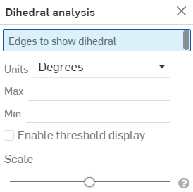
從功能表中選擇 [二面角分析] 來開啟對話方塊:
-
選擇一或多條邊線來顯示二面角度。
-
選擇您偏好的測量單位。
-
最大 - 當選取一或多條邊線時,系統會顯示最大的二面角度。
-
最小 - 當選取一或多條邊線時,系統會顯示最小的二面角度。
-
-
選擇性地選取「啟用閾值顯示」來啟用可自訂的高以及低的閾值欄位。
-
選擇性地使用「比例」滑桿來調整二面角梳形的長度。
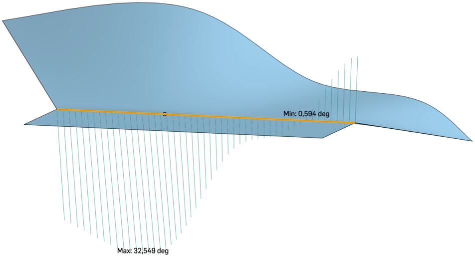
上方的圖片顯示在圖形區域中套用「二面角分析」工具於圖元邊線上的範例。
偵測與檢視在 Part Studio 或組合件中的任何干涉。
- 在 Part Studio 或組合件中有多個零件的情況下,按一下介面右下角的顯示分析工具功能表。
- 從功能表中選擇干涉偵測來開啟對話方塊。
- 選擇兩或多個零件以查看其間的干涉質量。
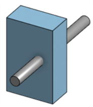
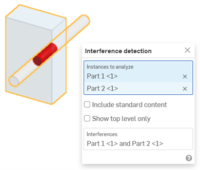
上圖中以紅色顯示干涉,並在對話方塊中「干涉偵測」的部分列出牽涉的零件。
將滑鼠移動至對話方塊中的零件名稱上暫留以在圖形區域中查看交叉的強調顯示。當選取了對話方塊中「干涉」欄位的情況下,圖形區域會調整配合至選取的干涉。將滑鼠移動至對話方塊中「干涉」的欄位上暫留,會在圖形區域中出現一個界限方塊,圍繞在模型中的干涉周圍。滑鼠移動暫留時,對話方塊中同時會出現界限方塊的長度/寬度/高度:
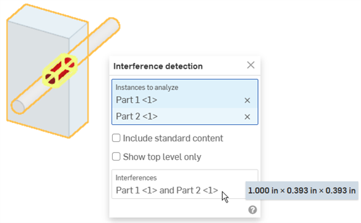
您可以使用方塊選擇來選取要干涉偵測的圖元:從左上拖曳至右下來包括僅完全被方塊所圍繞的零件或本體。從右下拖曳至左上來包括邊界方塊所接觸到的任何零件或本體。
-
(選用) 選擇包括標準內容來檢查與標準內容的干涉。
-
(選用) 選擇僅顯示最上層來隱藏對於所選次組合件為內部的干涉。
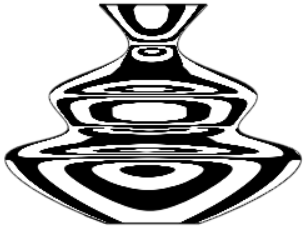
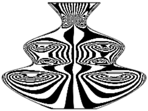
斑馬條紋代表在 Part Studio 或組合件中目前模型、面或曲面的條紋空間反射。這可以讓您查看橫跨邊線的曲率是否是對正及連續的。
-
按一下介面右下角的「顯示分析工具」 (
 )。
)。 -
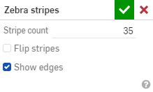
從功能表中選擇 [斑馬條紋] 來開啟對話方塊:
-
條紋數量 - 在每個曲面上顯示的曲率條紋數量
-
反轉條紋 - 反轉條紋。
-
顯示邊線 - 顯示零件面之間的邊線 (預設)。當取消核取時,會隱藏零件邊線。在某些情況中隱藏邊線可改善零件面間的曲線視覺顯示。
當曲率是橫跨邊線對齊時,邊線是平滑且條紋朝上,然後跨邊線改變方向:
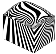
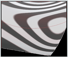
當曲率是橫跨邊線連續時,邊線是平滑且無跨邊線曲率的改變。條紋朝上且不會跨邊線改變方向:
範例:
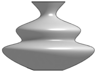
無曲率視覺化 |

預設曲率:35 個條紋 |
|
10 個條紋 |
35 個條紋;已反轉 |
當您接受「斑馬條紋」對話方塊 (點按核取記號) 時,對話方塊會關閉但條紋仍會顯示。若要關閉斑馬條紋的顯示,請再次從「顯示分析工具」功能表中選擇 [斑馬條紋],然後在對話方塊中按一下 X (從「曲率視覺化」功能表中選擇 [色彩對應] 也會關閉斑馬條紋)。
曲率色彩對應套用您選擇的漸層色彩到 Part Studio 中的面或曲面上以對曲率進行更深入的探查。您可以調整漸層色彩的色階,從不同類型的色彩對應中選擇,以獲得最佳的視覺呈現來辨識曲面連續性與邊線間的轉換。
-
按一下介面右下角的「顯示分析工具」(
 )。從功能表中選擇 [曲率色彩對應]:
這樣會將一個色彩對應套用到圖形區域中的面與曲面上,使用漸層色彩來以色階顯示曲率:
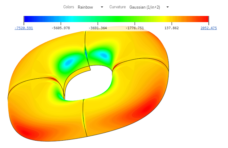
使用色彩對應視覺呈現曲率時可用的選項包括:
-
設定對應的色彩。按一下下拉功能表來選擇最適合您需求與視覺呈現喜好的色彩配置:
-
Viridis - 深紫到淺綠的色階
-
藍色 -> 紅色 - 藍色到紅色的色階
-
Plasma - 深藍到淺黃的色階
-
彩虹 - 彩虹的色階
-
-
選擇對應的圖形。按一下下拉功能表來選擇一個特定的圖形:
-
高斯 - 根據在給定點上最大與最小半徑的乘積來分配色彩。系統會將曲率顯示為半徑的倒數。
-
平均值 - 根據在給定點上最大與最小半徑的平均值來分配色彩。
-
最大半徑 - 根據在給定點上的最大半徑值來分配色彩。
-
最小半徑 - 根據在給定點上的最小半徑值來分配色彩。
-
您可以將色彩對應重新放置在圖形區域中的任何位置以改善模型的檢視與對應。將游標移動至圖形上暫留直至交叉游標出現。點按並拖曳圖形至新的位置。對於某些位置,圖形會重新定向至垂直的位置。不論圖形位於何處,「色彩」與「曲率」下拉清單會維持在圖形區域的上方。
提示
在曲面或面沒有曲率的情況下,由於並無半徑的計算,因此 Onshape 不會將任何值指定給色彩對應色階。系統仍會顯示色彩對應,且您還是可以從對應與色彩中選擇。如果沒有計算任何值,則不會套用曲率色彩。模型會維持為在開啟任何曲率分析工具之前相同的色彩。
您可以點按並將色階的端點彼此拉近來變更色階。系統會重新計算色階上的點,並根據新的色階重新整理面與曲面上的色彩。您也可以點按值並在欄位中輸入以調整色階。請確定按一下的重新整理小圖示。
使用拔模分析來在 Part Studio 中找出模型內不滿足指定最小拔模量的面,找出底切的區域,並查看所選幾何的潛在分模線位置。
- 按一下圖形區域右下角的「顯示分析工具」(
 )。從功能表中選擇 [拔模分析] 來開啟對話方塊與色彩圖例。在對話方塊中,選擇一個平面、面或邊線來指┬定「模具分割方向」。
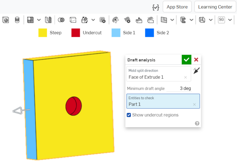
- 指定最小的拔模角度。
- 選擇要檢查的圖元。
- 使用「顯示底切區域」核取方塊來選擇性地關閉紅色底切的指示。
請注意到介面上方的拔模分析色彩圖例。
- 藍色的面表示面滿足拔模所指定的最小角度。
- 黃色的面表示這些面過陡 (小於指定的最小拔模)。
- 紅色的面是底切面。
您可以在模型上移動游標來查看個別拔模的精確角度:
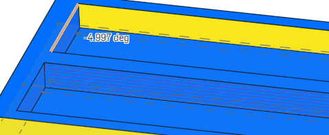
如同其他視覺化工具模式一樣,拔模分析會保持為啟用,直到您選擇了其他項目。在啟用時,您可以編輯零件來修正拔模,並查看立即的結果。您也可以使用剖面視圖來檢視模型內無法看到的地方。
拔模分析會自動在兩個方向上作用。Onshape 會以不同的顏色顯示可接受的拔模來指明方向:淡藍色是第一邊 (正向),深藍色則是第二邊 (負向)。操控器箭頭會指向第一邊,您可以使用對話方塊中的方向箭頭來反轉箭頭,像是上圖中「模具分割方向」欄位旁的箭頭。
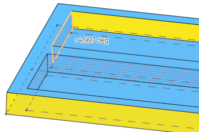
上方的圖片顯示點按方向箭頭反轉分析方向後的拔模角度:淺藍色表示是正方向,角度是以正角度顯示。對照再之前的圖片,深藍色表示是負方向,角度是以負角度顯示。
使用厚度分析來測量零件各個區域上的材料分佈量。
目前僅支援原生的 Onshape 零件與網格模型類型。
目前不支援封閉的複合件。
步驟
在至少包含一個零件的 Part Studio 中:
-
按一下圖形區域右下角的「顯示分析工具」(
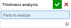
 )。從功能表中選擇 [厚度分析] 來開啟對話方塊:
-
選擇要分析的一或多個零件。
Onshape 立即開始計算厚度分析的要求。在圖形區域左下角的進度旋轉器會提供分析狀態的更新:
-
準備厚度分析中 - 離散與處理幾何以進行分析
-
處理厚度分析中 - 配置高效能雲端實例
-
計算厚度中 - 開始厚度分析的計算
-
精化厚度分析中 - 會有初步的結果,繼續處理以求更高的保真度結果
-
後處理厚度分析中 - 處理最終的結果並將快速提供
-
-
按一下綠色的核取記號來接受您的選擇並關閉對話方塊。厚度分析工具仍會保持為啟用的。當有初步的厚度分析結果時,色彩列會在圖形區域中開啟:

系統會自動渲染選取的零件。色彩列會將欄位值與您一或多個零件曲面顯示的色彩對應。
-
若要變更色彩配置,請從色彩下拉清單中選擇一個調色盤。
-
若要變更色彩列的範圍,請選擇下限或上限值並輸入一個新的數字。使用重新整理的按鈕來重設測量欄位中最低/最高值的限度。
另一種方式是,點按並拖曳下限或上限值上方的刻度線到圖例上的新位置。若要完全重新設定色彩列的位置,請將游標移動至色彩列上暫留,當色彩列變為啟用時,按一下並將圖例拖曳到您螢幕中的新位置上。
除非手動調整,否則在精化居間厚度分析結果時,圖例的界限可能會自動調整為新的限制。在手動調整之後,居間的更新不會導致上限或下限的改變。不過,色彩列上最遠端的值可能會在有新資訊時更新。
圖例對使用者定義界限之外的欄位值顯示獨特的色彩。核取「暗色階」選項來建立三色的視圖並快速存取您目標範圍外的區域。

-
從「方法」下拉功能表中選擇所需的方法:
-
滾球
-
滾球梯度 (%)
-
射線
-
射線梯度 (%)
在使用厚度分析時,您可以繼續正常地在 Part Studio 中操作。在您進行編輯時,厚度評估會自動更新。
-
-
若要編輯厚度分析,按一下圖形區域右下角的「顯示分析工具」(
 ),然後從功能表中選擇 [編輯厚度分析]。
 -
若要關閉厚度分析,按一下「顯示分析工具」(
 ),然後選擇 [關閉厚度分析]。
滾球厚度方法
滾球厚度方法計算零件曲面上每個點可內接的最大球體尺寸。
球體是與檢查點相切的,且和零件上的至少一個其他點相切 (儘管有可能與多個零件相切),因此可以說它是沿著零件的內部滾動,並同時改變大小。系統會以內切球體的直徑來報告測量的厚度。
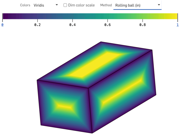
提示
-
滾球厚度方法提供在欲探查區域內多個點上由局部、非普通幾何關係定義而來的厚度測量值。
-
滾球厚度分佈是保證在任何實體零件的所有區域都是連續的。
射線厚度方法
射線厚度方法計算沿直線路徑穿過零件內部行進的距離。
在零件曲面的每個點上,會有一條射線垂直投射到該曲面,終止於與零件另一點的第一個交點上。這兩點之間的線段長度就是射線的厚度。
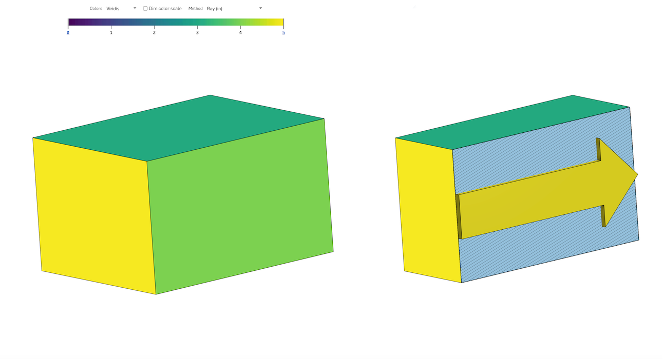
提示
-
沿著零件曲面垂直投影到一個點的直線並不能保證與零件曲面的第二點有任何幾何關係。
-
射線厚度的分佈很少在整個零件上連續,其包含明顯的不連續性,特別是在尖銳的轉角處。
厚度梯度 (射線法或滾球法)
厚度梯度測量沿零件曲面移動時零件厚度的變化速度。值本身是下列術語的比率 (A/B):
-
從零件曲面的一個點沿任意方向移動 (名義上和瞬間) 時,厚度可以增加或收縮的最大量,以長度單位來測量。
-
沿所述方向行進的名義瞬間測地距離,以相同的長度單位來測量。
比率是無因次、非負值並以非常規的百分比 (%) 表示。
展平曲面會從一或多個連續的非平坦面產生一個平坦的曲面。
這個工具會執行幾何的展平以建立有最小應變的曲面。
展平操作會忽略展平曲面處零件材料的屬性。所產生的曲面並沒有任何材料屬性。
展平曲面的一些用途:
-
評估套用至零件某些區域的塗漆遮罩的平坦 (切割) 形狀。
-
評估在沒有過度應變或皺折的情況下,將印花套用至零件彎曲區域的可行性。
-
在給定的外模線 (OML) 與層邊界的條件下,決定複合層的切割形狀。
-
將特徵 (挖空、文字曲線、文字換行) 加入至平坦曲面上,然後讓它們重新形成回彎曲曲面的形狀。
製造商與組裝者通常會將印花、包材或覆蓋物套用到表面上。這些東西一般都是從平坦的片材而來,但它們要黏附的表面並不一定是平坦的。Onshape 的「展平曲面」工具可從一或多個連續的非平坦曲面產生一個平坦的曲面,因而得以進行平滑的應用。
當您套用平坦的片材到非平坦的曲面上時,材料會不可避免的伸展與壓縮。Onshape 的展平曲面工具會執行幾何的展平來建立有最小應變能的曲面。
展平的曲面不會考慮材料的定義。因而產生的平坦曲面並沒有材料的屬性。
這款刮刀手柄需要一個紋理狀的握把包材。
在 Part Studio 中按一下圖形區域右下角的「顯示分析工具」圖示 ,然後選擇 [展平曲面]。
選擇要展平的一或多個連續面,然後按一下 [展平] 按鈕來執行展平的操作。
「展平曲面」工具提供多個視覺呈現選項以提供回饋。「顯示小面」會同時在原始與展平的曲面上顯示網格小面。
停用「顯示小面」時,「顯示邊線」會在展平曲面上顯示邊線。
「顯示棋盤格」會同時在原始與展平的曲面上顯示棋盤格圖案。可輸入「棋盤格比例」來調整圖案的比例。較低的值會產生較大的棋盤格方格,較高的值則會產生較小的方格。
「顯示扭曲」會顯示展平過程中幾何扭曲的展平曲面區域。系統會以紅色或藍色顯示有扭曲的區域。藍色表示張力或拉伸,紅色則表示壓縮或皺摺。顏色較重的區域代表有較高的扭曲值。
核取「顯示展平」來顯示產生的曲面。
選擇曲面要相對於其展平的一個「原點」。如果您沒有選擇一個原點,Onshape 會自動為展平曲面選擇一個原點。
藉由輸入一個「展平偏移」或「展平角度」值來進一步定位平坦曲面。
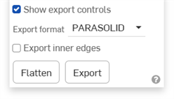
「展平曲面」工具不會在「零件」清單中建立一個零件。核取「顯示匯出控制項」│來顯示匯出的選項。將平坦的曲面匯出至 Parasolid 或 STL 來在檔案中得到曲面的物理呈現。如果需要,可以使用「衍生」特徵來將檔案匯回到 Part Studio 中。
另一方法是選擇 SVG 或 DXF 做為匯出格式,然後按一下 [匯出] 按鈕來將檔案送至您的裝置中。然後您可以在像是 Adobe Illustrator 等的外部軟體中操作印花。
仔細檢查這個平坦曲面後發現把手底部有嚴重扭曲。退出「展平曲面」工具,然後套用一個分割特徵來加入額外的邊線到面中。
選擇「展平曲面」,然後為「裂邊」選擇一條邊線。按一下 [展平]。系統會沿著所選邊線分割或裂開平坦曲面,減輕拉伸和皺摺造成的應變。
在 Part Studio 中:
-
按一下圖形區域右下角的「顯示分析工具」(
 )。從功能表中選擇展平曲面來開啟對話方塊:
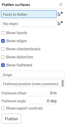
-
在選取了要展平的面欄位的情況下,於圖形區域中選擇一或多個連續的面。
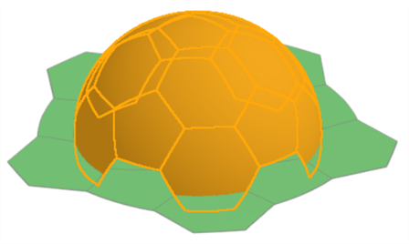
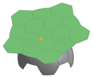
展開足球一部分的範例。注意到您必須先按下 展平 按鈕才能顯示結果。
-
在對話方塊中按一下來選擇裂邊欄位,然後在圖形區域中選擇展平曲面應於該處裂開的邊線。
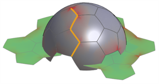
使用裂邊的範例。注意到這樣可幫助減少在展平曲面上的扭曲。請將這個圖片與下方「顯示扭曲」選項之下出現的圖片做比較。
-
核取下列選擇性的顯示設定,然後輸入適當的輸入值:
-
顯示小面 - 核取來同時在原始與展平的曲面上顯示網格小面。
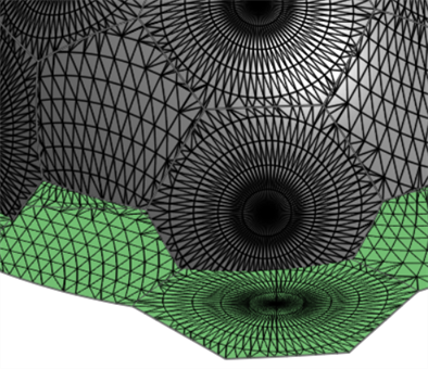
-
顯示邊線 - 根據預設,系統會顯示在平坦曲面上的邊線。取消核取來隱藏這些邊線。
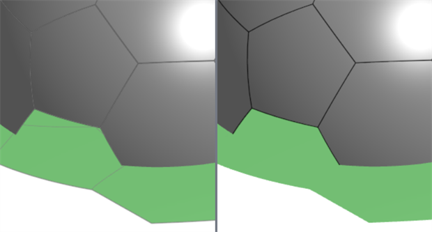
啟用「顯示邊線」(左圖) 與停用 (右圖)
-
顯示棋盤格 - 核取來顯示同時覆蓋在原始與展平曲面上的黑白棋盤格圖案。
-
棋盤格比例 - 設定棋盤格圖案的比例。較低的值會產生較大的圖案方格。較高的值則會產生較小的圖案方格。
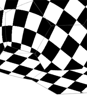
顯示棋盤格;棋盤格比例:25
-
-
顯示扭曲 - 以紫紅色顯示展平過程中造成其上幾何扭曲的展平曲面區域。顏色越深表示有更多的扭曲。
-
扭曲比例 - 設定要報告扭曲的敏感程度。較高的值會增加扭曲的敏感性 (系統會報告更多的扭曲)。較低的值會減少扭曲敏感性 (報告較少的扭曲)。
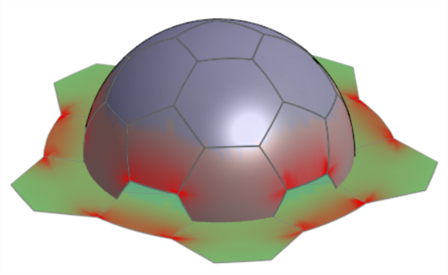
-
-
顯示展平 - 顯示展平的結果。這可讓您切換開啟或關閉展平的結果。
-
展平位置 (結合連接器) - 選擇一個結合連接器來定位展平曲面的位置,而不是放在所選曲面下方。
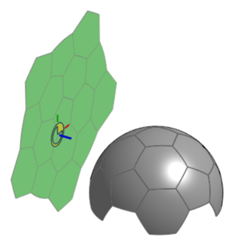
-
展平偏移 - 如果在「展平位置」中使用了結合連接器,請輸入一個正或負的數值來沿著結合連接器的 Z 軸偏移這個位置。
-
展平角度 - 如果在「展平位置」中使用了結合連接器,請輸入一個正或負的角度值來相對結合連接器的 Z 軸偏移這個位置。
-
-
原點 - 為產生的平坦曲面選擇一個頂點來用做為原點。
-
-
按一下顯示匯出控制項來顯示匯出選項:
-
匯出格式 - 從檔案格式選項清單中選擇:PARASOLID、STL、DXF、或 SVG。
-
匯出內邊線 - 如果「要展平的面」包含多個面則會匯出內邊線。
範例
-
匯出按鈕 - 按一下 匯出 按鈕來將最終的展平曲面結果下載到您的裝置中。
-
-
按一下 展平 來顯示用對話方塊輸入項產生的最終展平曲面。
展平來得到一個印花或塗漆遮罩曲面。
「展平曲面」的用途之一是從多個非平坦曲面中擷取出一個平坦曲面,以用做為印花或塗漆遮罩。
在下方的影像中,側視看起來像是一個完美的圓形。但實際上您會需要先擷取彎曲的曲面,將其ˊ展平、套用一個印花,然後再將印花套用在彎曲的曲面上:
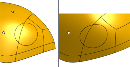
使用「展平曲面」工ˋ具來得到印花的挖空:
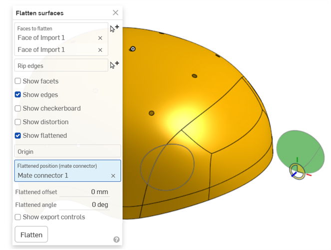
在您得到曲面之後,核取顯示匯出控制項,選擇 SVG 或 DXF 做為匯出格式,然後按一下 [匯出] 按鈕來將檔案送至您的裝置中。然後您可以在像是 Adobe Illustrator 等的外部軟體中操作印花。
匯出內邊線
與上方相同的範例,分別是沒有與有選取了匯出內邊線 (在對話方塊中「顯示匯出控制項」部分之下):
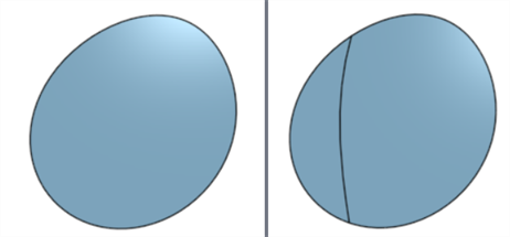
停用 (左圖) 與啟用 (右圖)「匯出內邊線」
展平管子
在這個範例中要展開一個圓管。這是一個可以開發的曲面,要加入一個裂邊來產生沒有扭曲的平坦曲面:
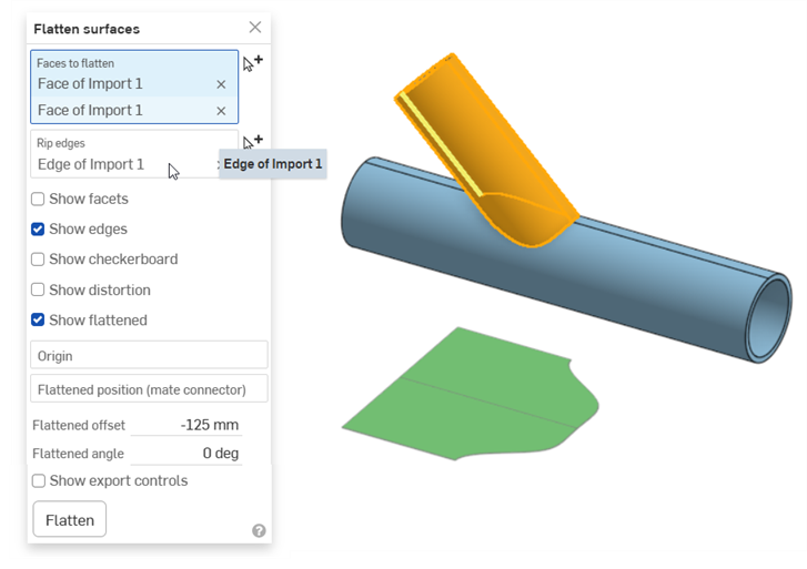
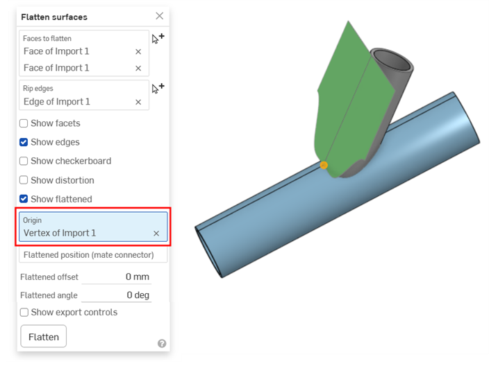
將原點設定為管子頂端的頂點可讓您視覺查看曲面沿著管邊展平的情況:
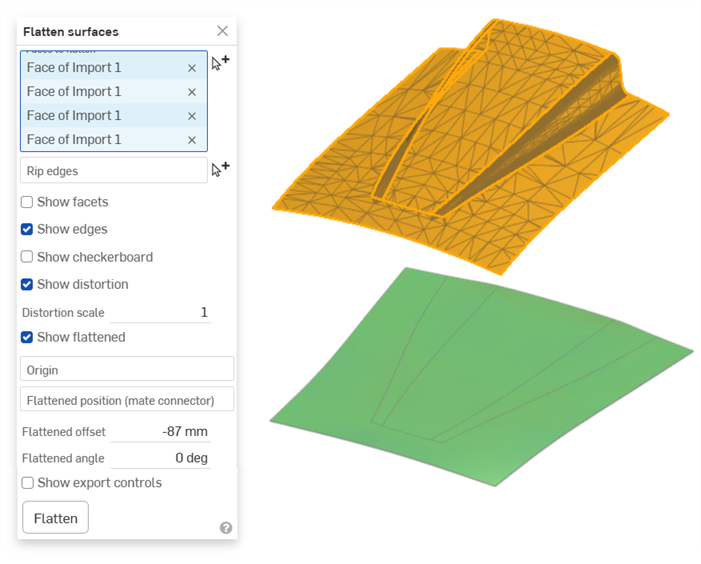
汽車引擎蓋
這個範例顯示以網格匯入帶入至 Onshape 中汽車引擎蓋的掃描曲面。通常您會要建立這個曲面的漆面保護膜 (PPF)。這在引擎蓋、擋泥板、頭燈前表面、和其他彎曲表面上是相當有用的。匯入會是展平的且幾乎沒有顯示任何扭曲:
-
如果有更新某些選項,會需要再次按下 展平 按鈕。例如,如果加入了裂邊,或選取了原點。
-
「展平曲面」工工具不會在「零件」清單中建立一個零件。匯出展平曲面來在一個檔案中得到曲面的呈現。如果需要,可以將這個檔案匯入回 Part Studio 中。
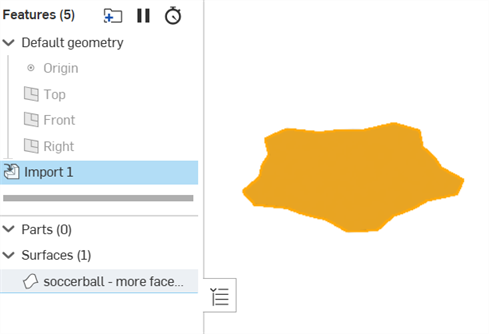
匯入的展平曲面的範例。使用 PARASOLID 檔案格式來匯入曲面,匯入至一文件,然後使用「衍生」特徵來匯入至 Part Studio 中。
-
展平曲面並沒有提供完美的正確性。您不應使用展平曲面來得到關鍵或精細的測量來用於計算中。應ˋ將其用於提供一般的尺寸以包覆物件,像是繞非平坦曲面套用印花。
