 Isoparametric Curve
![]()
![]()
![]()
Create smooth curves that run along a face or surface in the U or V direction.
Similar to a weave of cloth, every surface is roughly rectangular. Surfaces have three directions: U, V, and Normal. The Boundary surface profiles U and V represent the X and Y directions of the surface, respectively.
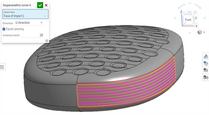
Use these curves with other features. For example, you can split the face using the curves. Then, use the Delete Face feature to remove the center portion. Once removed, you can add a ruled surface, 3D Fit splines, and Loft.
Isoparametric curves are smooth curves that run along a face or surface in the U or V direction. The Isoparametric curve feature adds selectable curve entities to the Part Studio for reference in other features.
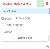
Start a new isoparametric curve feature. Select a face to apply the curves to. The face can be on a solid body or surface. The Direction dropdown allows you to select either the U or V direction to place the curves. The Equal spacing checkbox changes how the location of the curves along the surface are defined. To specify a number of evenly spaced curves along the face, check Equal spacing and input an Instance count.
To create curves based on position, leave Equal spacing unchecked. Inside the Positions group box, click Add Curve. Set a Location or select a point to place the curve. Location is relative to the selected face, represented as a percentage. Input a value between 0 and 1. A value of 0.5 places the curve at the center of the face. Check Select point and pick a point, vertex, or explicit mate connector. Optionally, add an implicit mate connector by selecting the Mate connector icon to the right of the field.
To add additional curves, click Add Curve and repeat the process. Click X to remove a single curve or Clear to remove all curves. Once placed, accept the feature.
Use these curves with other features. For example, split the face using the curves. Then, use the Delete Face feature to remove the center portion. Once removed, add a ruled surface, two 3D fit splines, and finish with a loft.
With at least one face or surface in the graphics area:
- Click
 .
.
- With focus in the Select face field, click the face(s) and/or surface(s) on which to create the curve.
- Select a direction:
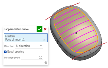
- U direction - Curves will run in the X direction of the surface.
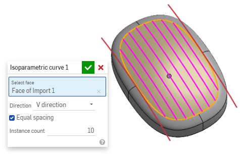
- V direction - Curves will run in the Y direction of the surface.
- U direction - Curves will run in the X direction of the surface.
- Select the location for the curves:
- To place a set number of equally spaced curves:
- Check the Equal spacing option.
- Enter the number of curves in the Instance count field.
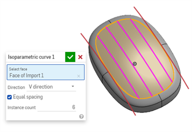
- To specify a precise location for a curve:
- Uncheck the Equal spacing option.
- Click Add Curve.
- Input a value between 0 and 1 in the Location field. The Location is relative to the selected face, so a value of 0.5 places the curve at the face's center.
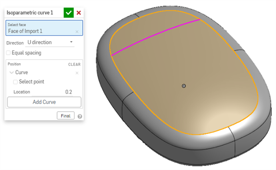
- To choose a sketch point as the curve location:
- Uncheck the Equal spacing option.
- Click Add Curve,
- With focus in the Select point field, click a sketch point in the graphics area.
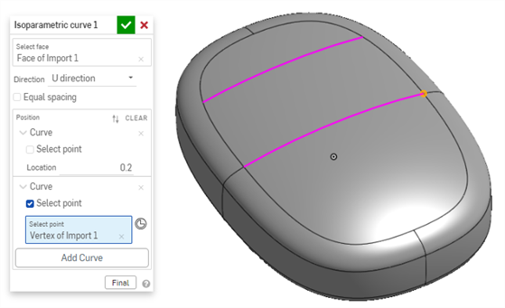
- To choose a mate connector as the curve location:
- Uncheck the Equal spacing option.
- Click Add Curve,
- Click the Mate connector icon.
- Select a Mate connector in the graphics area.
- Optionally, click the Mate connector in the Select point field to open the Mate connector dialog. Edit the Mate connector as needed, then close the Mate connector dialog.
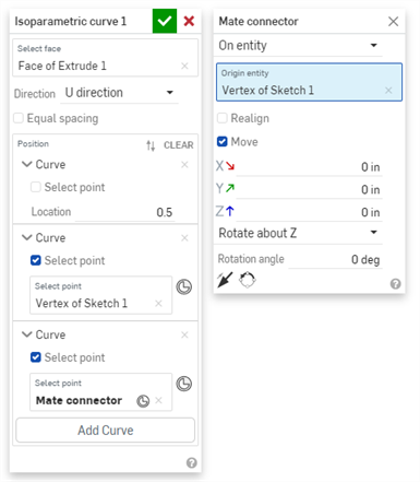
- To place a set number of equally spaced curves:
- Click
 to accept.
-
Click the X in the Position field to remove a defined curve.
-
Click CLEAR in the Position field to remove all defined curves.
-
The numeric fields in the Isoparametric curve dialog have slightly different keyboard+scroll shortcuts than other Onshape dialogs.
Isoparametric Curve Dialog 滾動+按鍵 結果 Scroll wheel default Increments of 1.0 Ctrl+滾輪 Increments of 0.01 Shift+滾輪 No effect
In addition to the surfacing tools, curves are used to create the basic building blocks of surfaces.
這個清單是曲線特徵工具的集合,並非詳盡的清單。在操控曲線時,可能會使用其他的特徵工具。
- 草圖工具 - 草圖工具列中的工具,像是直線、轉角矩形、中心點矩形、中心點畫圓、三點畫圓、切線弧、三點定弧、樣條、點與建構線,可用來建立 Part Studio 中的草圖。
-
 螺旋線 - 使用圓錐或圓柱面、單一軸或結合連接器的 z 軸、或是環狀邊線來建立螺旋線。
 -
 3D 擬合樣條 - 建立穿過連續頂點的 3D 擬合樣條。建立列在零件清單中「曲線」之下的曲線。
 -
 投影曲線 - 建立一條來自兩個草圖投影的曲線 (「兩個草圖」選項),或是建立一條來自曲線投影至面的曲線 (「曲線到面」選項)。
 -
 橋接曲線 - 建立連接任兩個點、頂點或結合連接器的一條曲線。所產生的曲線會列於「特徵」清單與「零件」清單中。
 -
 複合曲線 - 以一條曲線來代表多條邊線。選擇多條相鄰的邊線、草圖圖元、與其他的曲線。選擇非連續的邊線會建立多條的曲線。為每條曲線做出的選擇項目必須在其頂點處交會 (曲線會列於「零件」>「曲線」清單之中)。
 -
 相交曲線 -在兩或多個曲面或面的相交處建立一條曲線。選取的項目必須是相交的。
 -
 修剪曲線 -根據距離修剪或延伸曲線,或是修剪或延伸至邊界圖元。
 -
 等傾線 - 在斜面上建立一條等傾線。等傾線會出現在面相較於其參考定義有某些傾斜的位置。所產生的等傾線會列於「特徵」清單與「零件」清單中。
 -
 偏移曲線 - 藉由在周圍面上偏移邊線來建立與延伸和/或分割新的曲線。
 -
 等參數曲線 - 建立沿面或曲面的 U 方向或 V 方向延伸的平滑曲線。
 -
 編輯曲線 - 選擇草圖圖元或曲線來套用簡化的近似、提高度數、重新定位控制曲線頂點和/或平化至任何 2D 平面來編輯現有的曲線。
 -
 路線曲線 - 建立在 3D 空間中跨越一個或多個平面的多點曲線 (路線路徑)。這對於建立管路路線、配線、以及進階曲面建立中的 NURBS 曲線是非常有用的。
iOS and Android support for the Isoparametric curve feature is limited to displaying and editing existing curves. Isoparametric curves can only be created on the desktop (browser) platform. They cannot be created on iOS or Android platforms.