 3D 擬合樣條
![]()
![]()
![]()
建立穿過連續頂點的3D 擬合樣條。建立列在零件清單中曲線之下的曲線。
3D 擬合樣條在所選草圖點、其他曲線端點、零件端點或選擇的相切邊線或曲線之間擬合一條曲率連續的樣條。可使用它來建立路線的路徑,橋接圖元,建立掃掠或疊層拉伸特徵的路徑或導引,或是用在建立複雜的輪廓之中。
若要建立 3D 擬合樣條,請從特徵工具列中選擇這個特徵。若要從頂點建立樣條,請根據要樣條行進的順序選擇想要的點。同樣地,若要從邊線或曲線建立樣條,切換至「邊線」的分頁,然後選擇邊線和/或相切曲線的組合。如果您要調整選取項目的順序,按一下「重新排序項目」選項,然後用抓握控制棒拖曳項目。當完成時,選擇「完成」來結束重新排序。
根據頂點來定義 3D 擬合樣條時會有幾個可用的其他選項:如果樣條應是封閉的,請核取「封閉樣條」。這個選項會將樣條圈回至起點。當建立開放的樣條時,請定義樣條的開始或終止方向。做出的選擇會定義所選圖元與開始或終止方向的相切性。
可以使用數個不同的圖元來定義方向,包括零件或曲面的邊線、其他曲線、草圖圖元、平面或是結合連接器。切換「相反方向」箭頭來反轉相切的方向。量值是套用至計算的縮放係數,可進一步定義曲線的形狀。
如果樣條的開始或結束處應與所選方向的曲率相配,請在個別核取在開始或結束處配對曲率。如果沒有選擇開始或終止的方向,樣條的開始與結束會與第一個和最後選取的點或頂點位置相配。
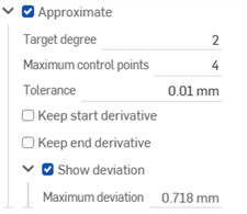
頂點和邊緣控制的樣條兩者都可以近似。核取「近似」來簡化樣條。設定「目標度數」、「最多控制點」的數量、與「公差」。核取「保持開始導數」與「保持結束導數」來保持樣條在兩端的相切性。核取「顯示偏差」來檢視原始與近似後樣條間的最大偏差。「近似」選項會以黃色來顯示原始的樣條,以紫紅色顯示新的近似樣條。
在選擇了選項之後,請接受特徵,然後系統馬上會將一條曲線加入至「曲線」清單中。使用「曲線」清單中隱藏/顯示的功能來隱藏或顯示由 3D 擬合樣條建立的曲線。
- 按一下
 。
。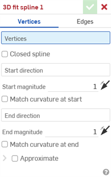
- 在對話方塊最上方按一下來選擇要使用頂點或邊線。
- 對於使用頂點建立的樣條:
- 按一下來選擇頂點,建立沿著頂點的 3D 擬合樣條。
- 選擇性地核取方塊來建立封閉的樣條。
- 如果樣條不是封閉的,您可以選擇要按一下線或結合連接器 (隱含或明確的) 以選取開始方向。
- 輸入一個值,或是在圖形區域中按一下並拖曳方向箭頭來調整開始量值。
- 選擇性使用,按一下來選取在開始處配對曲率來將所選邊線或面的曲率與開始方向相配。
- 選擇性地點按線或結合連接器 (隱含或明確的) 以選取終止方向。
- 輸入一個值,或是在圖形區域中按一下並拖曳方向箭頭來調整結束量值。
- 選擇性使用,按一下來選取在結束處配對曲率來將所選邊線或面的曲率與終止方向相配。
- 對於使用邊線所建立的樣條,點按來選取相切的連續邊線來以建立 3D 擬合樣條。
- 對於使用頂點建立的樣條:
-
Complex curves can be reapproximated to create simpler curves. Check Approximate to open options to reapproximate the curve. The original curve is displayed in orange, and the new approximated curve is displayed in magenta.
- Target degree - Enter the target curve degree for the selected curve.
- Maximum control points - Enter the maximum number of control points allowed for the selected curve.
- Tolerance - Tolerance of the selected curve, as a length measurement. Enter the tolerance value.
- Keep start derivative - Check to keep tangency at the beginning of the selected curve.
- Keep end derivative - Check to keep tangency at the ending of the selected curve.
- Show deviation - Check to view the maximum deviation between the original curve and the reapproximated curve.
- 按一下
 。
。
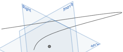
會建立一條曲線,列在零件清單中曲線之下。您無法顯示/隱藏此 3D 擬合樣條特徵;請改用曲線 (零件) 中的顯示/隱藏功能。
- 按一下
 。
。 - 選擇邊線 (必須是連續相切的) 來建立 3D 擬合樣條。
- 核取方塊來建立樣條。
- 按一下
 。
。
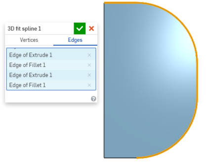
- 按一下
 。
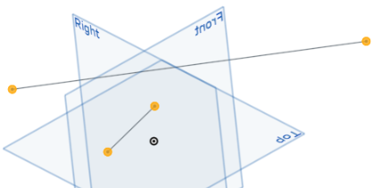
。 - 選擇頂點來建立 3D 擬合樣條。
- 核取方塊來建立封閉的樣條。
- 按一下
 。
。

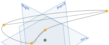
- 按一下
 。
。 - 選擇頂點來建立 3D 擬合樣條:
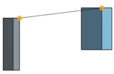
- 選擇開始與終止方向 (強調顯示的邊線):
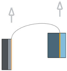
- 選擇在開始處配對曲率與在結束處配對曲率:
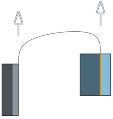
- 按一下
 。
。
除了曲面建構工具之外,還可使用曲線來建立曲面的基本建構塊。
這個清單是曲線特徵工具的集合,並非詳盡的清單。在操控曲線時,可能會使用其他的特徵工具。
- 草圖工具 - 草圖工具列中的工具,像是直線、轉角矩形、中心點矩形、中心點畫圓、三點畫圓、切線弧、三點定弧、樣條、點與建構線,可用來建立 Part Studio 中的草圖。
-
 螺旋線 - 使用圓錐或圓柱面、單一軸或結合連接器的 z 軸、或是環狀邊線來建立螺旋線。
 -
 3D 擬合樣條 - 建立穿過連續頂點的 3D 擬合樣條。建立列在零件清單中「曲線」之下的曲線。
 -
 投影曲線 - 建立一條來自兩個草圖投影的曲線 (「兩個草圖」選項),或是建立一條來自曲線投影至面的曲線 (「曲線到面」選項)。
 -
 橋接曲線 - 建立連接任兩個點、頂點或結合連接器的一條曲線。所產生的曲線會列於「特徵」清單與「零件」清單中。
 -
 複合曲線 - 以一條曲線來代表多條邊線。選擇多條相鄰的邊線、草圖圖元、與其他的曲線。選擇非連續的邊線會建立多條的曲線。為每條曲線做出的選擇項目必須在其頂點處交會 (曲線會列於「零件」>「曲線」清單之中)。
 -
 相交曲線 -在兩或多個曲面或面的相交處建立一條曲線。選取的項目必須是相交的。
 -
 修剪曲線 -根據距離修剪或延伸曲線,或是修剪或延伸至邊界圖元。
 -
 等傾線 - 在斜面上建立一條等傾線。等傾線會出現在面相較於其參考定義有某些傾斜的位置。所產生的等傾線會列於「特徵」清單與「零件」清單中。
 -
 偏移曲線 - 藉由在周圍面上偏移邊線來建立與延伸和/或分割新的曲線。
 -
 等參數曲線 - 建立沿面或曲面的 U 方向或 V 方向延伸的平滑曲線。
 -
 編輯曲線 - 選擇草圖圖元或曲線來套用簡化的近似、提高度數、重新定位控制曲線頂點和/或平化至任何 2D 平面來編輯現有的曲線。
 -
 路線曲線 - 建立在 3D 空間中跨越一個或多個平面的多點曲線 (路線路徑)。這對於建立管路路線、配線、以及進階曲面建立中的 NURBS 曲線是非常有用的。
- 輕觸「3D 擬合樣條」工具圖示 (
 )。
)。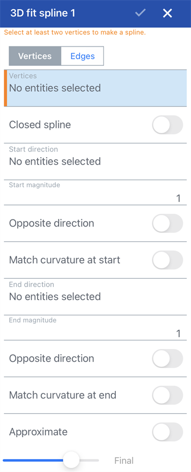
- 在對話方塊最上方輕觸來選擇要使用頂點或邊線。
- 對於使用頂點建立的樣條:
- 輕觸來選擇頂點,建立沿著頂點的 3D 擬合樣條。
- 選擇性地核取方塊來建立封閉的樣條。
- 如果樣條不是封閉的,您可以選擇要按一下線或結合連接器 (隱含或明確的) 以選取開始方向。
- 輸入一個值,或是在圖形區域中拖曳方向箭頭來調整開始量值。
- 選擇性地選取在開始處配對曲率來將所選邊線或面的曲率與開始方向相配。
- 選擇性地選取線或結合連接器 (隱含或明確的) 以選擇終止方向。
- 輸入一個值,或是在圖形區域中拖曳方向箭頭來調整結束量值。
- 選擇性地選取在結束處配對曲率來將所選邊線或面的曲率與終止方向相配。
- 對於使用邊線所建立的樣條,選取相切的連續邊線來建立 3D 擬合樣條。
- 對於使用頂點建立的樣條:
- 輕觸核取記號。
會建立一條曲線,列在零件清單中曲線之下。您無法顯示/隱藏此 3D 擬合樣條特徵;請改用曲線 (零件) 中的顯示/隱藏功能。


- 輕觸「3D 擬合樣條」工具圖示 (
 )。
)。 - 選擇頂點來建立 3d 擬合樣條。
- 核取方塊來建立封閉的樣條。
- 輕觸核取記號。


- 輕觸 3D 擬合樣條工具。


- 在對話方塊最上方輕觸來選擇要使用頂點或邊線。
- 對於使用頂點建立的樣條:
- 輕觸來選擇頂點,建立沿著頂點的 3D 擬合樣條。
- 選擇性地核取方塊來建立封閉的樣條。
- 如果樣條不是封閉的,您可以選擇要按一下線或結合連接器 (隱含或明確的) 以選取開始方向。
- 輸入一個值,或是在圖形區域中拖曳方向箭頭來調整開始量值。
- 選擇性地選取在開始處配對曲率來將所選邊線或面的曲率與開始方向相配。
- 選擇性地選取線或結合連接器 (隱含或明確的) 以選擇終止方向。
- 輸入一個值,或是在圖形區域中拖曳方向箭頭來調整結束量值。
- 選擇性地選取在結束處配對曲率來將所選邊線或面的曲率與終止方向相配。
- 對於使用邊線所建立的樣條,選取相切的連續邊線來建立 3D 擬合樣條。
- 對於使用頂點建立的樣條:
- 輕觸核取記號。
會建立一條曲線,列在零件清單中曲線之下。您無法顯示/隱藏此 3D 擬合樣條特徵;請改用曲線 (零件) 中的顯示/隱藏功能。


- 輕觸 3D 擬合樣條工具。

- 選擇頂點來建立 3d 擬合樣條。
- 核取方塊來建立封閉的樣條。
- 輕觸核取記號。
