 路線曲線
路線曲線
![]()
![]()
![]()
建立在 3D 空間中跨越一個或多個平面的多點曲線 (路線路徑)。這對於建立管路路線、配線、以及進階曲面建立中的 NURBS 曲線是非常有用的。
- Click the Routing curve feature (
 ) on the feature toolbar to open the Routing curve dialog (first image below). The triad manipulator is visible in the graphics area and is placed on the Part Studio origin point (second image below):
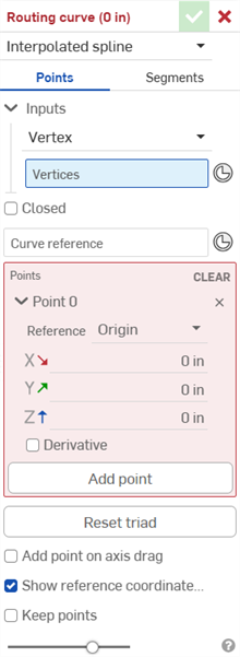
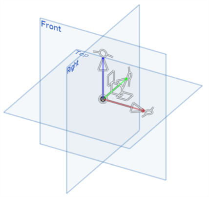
The triad manipulator adjusts:
Translation across 3 axes
Rotation about 3 axes
Translation across 3 planes.
Triad manipulator origin point.
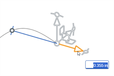
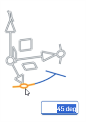
Adjusting the translation (first image below) or rotation (second image below) along one of the axes creates a solid blue line with a bar at the start. This indicates the distance or angle traveled from the start to the manipulator's origin (destination). An input box also opens where the distance or rotation can be entered numerically:
- Select the curve type:
- Interpolated spline - Creates a cubic (degree 3) interpolated spline through all points.
- Polyline - Creates line segments between each point in the curve.
- Bend radius - Adds a global Bend radius (length) value for the bend between each segment. The default value is 0 (no bend). This value can be overwritten when editing the individual point:
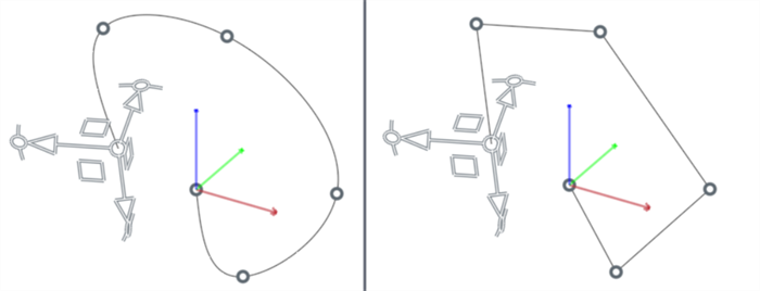
Interpolated spline (left); Polyline (right)
- 選擇點。這樣可編輯路線曲線的點。

- 在輸入項部分的下方,輸入所需的輸入類型與輸入選項:
- 頂點 - 選擇要於其上放置點的一或多個頂點或是結合連接器。
- 頂點 - 選擇一或多個頂點或是結合連接器 (
 )。
)。
- 頂點 - 選擇一或多個頂點或是結合連接器 (
- 曲線 - 使用一或多條邊線來在上面放置點。
- 邊線 - 選擇一或多條邊線。
- 樣本數 - 要放置在所選輸入邊線上點數量的整數值。
- 覆寫點 - 當核取時,如果先前已處理過某條邊線,以不同的「樣本數」再次選擇這條邊線會覆寫在輸入邊線上之前處理的點。系統不會覆寫在輸入邊線上的任何草圖點。
- 處理 - 在選取了輸入邊線與樣本數的情況下,按下處理按鈕來在邊線上平均放置這個指定的點數。
- CSV 檔案 - 在目前文件或連結的文件中選擇一個 CSV 檔案。這樣會將 CSV 檔案以點清單匯入。
- 表格 - 按一下來開啟選擇 CSV 檔案對話方塊。
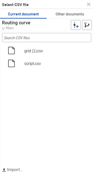
- 選擇 CSV 檔案 - 按一下這個欄位來開啟與點按「表格」時出現的同一選擇 CSV 檔案對話方塊。接著從目前文件或其他文件中選擇一個 CSV 檔案。按一下對話方塊底部的 [匯入] 按鈕來找出並匯入 CSV 檔案:
- 資料起始欄 - 如果您的 CSV 檔案包含多個欄位且資料並不是從欄 A (資料起始欄 0) 開始的,您可以指定一個資料要從該處開始的整數 (X 軸欄)。
- 單位 - 套用至 CSV 檔案資料的測量單位。選項有Centimeter、Foot、Inch、Millimeter、Meter、或 Yard。
- 覆寫點 - 如果先前已處理過某一 CSV 檔案,選擇相同或新的 CSV 檔案會覆寫先前處理過的檔案。
- 處理 - 在選取了 CSV 檔案的情況下,按下處理按鈕來將檔案中設置的點放置在圖形區域中。系統會建立一條穿過所有點的插值樣條 (插值樣條),或建立每個點之間的線段 (聚合線)。
- 頂點 - 選擇要於其上放置點的一或多個頂點或是結合連接器。
- 核取封閉來建立封閉 (週期) 曲線。
- 按一下曲線參考欄位,然後選擇一個頂點或結合連接器 (
 ) 來用做為路線曲線的全域參考座標系統。預設是設定為原點。
 - 檢視與編輯目前選取的點。除了提供建立新點與清除所有路線曲線點的功能外,這個區域還決定了目前點的參考、偏移值、與局部彎折半徑值:
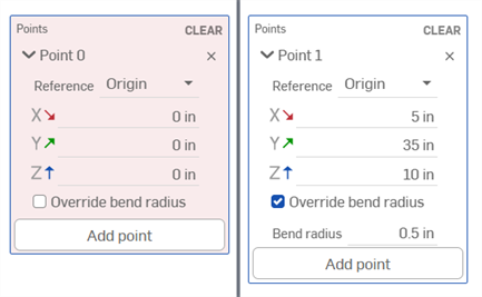
「點」顯示中沒有建立點 (左圖) 與建立了點 (右圖)
- 清除 - 按一下來刪除路線曲線上的所有點。
- 目前點 (點 0、點 1 等等) - 此處顯示的選項與在圖形區域中目前所選的路線曲線點相關。首先請選擇您要編輯的點,然後設定下列的參數:
- x/刪除點 - 從路線曲線中刪除目前選取的點。
- 參考 - 相對於下列參考之一的目前點的 X/Y/Z 偏移值:
- 原點 - 目前點是相對於 Part Studio 原點的 (預設)。
- 頂點 - 目前點是相對於頂點或結合連接器的。在圖形區域中選擇一個頂點,或按一下選擇結合連接器圖示 (
 ),然後在您模型的一個位置上按一下來建立結合連接器。
 - 曲線 - 目前點是相對於一或多條曲線的。按一下對話方塊中的「邊線」欄位,然後在圖形區域中選擇一或多條邊線。
- 相對 - 目前點是相對於之前的路線曲線點。
無法將曲線中的第一個點設定為與一先前的點相對的。
- X/Y/Z 偏移 - 顯示點從原點、點參考、或先前點 (由使用者定義) 偏移的目前位置。如果需要,請在每個欄位中輸入偏移數值。
- 覆寫彎折半徑 - 核取來為目前點覆寫全域彎折半徑。
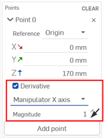
導數 - 僅當選取插值樣條時可用,這會控制在給定點的曲線導數 (相切方向)。使用三向操控器的平移和/或旋轉操控器來將導數對齊。此外,將三向操控器的對齊從 X 調整到 Y 或 Z 軸,並調整量值參數來影響控制的強度 (影響性)。
選擇方向選項來將導數與方向而不是 X/Y/Z 軸對齊。一個方向欄位開啟,您可以在圖形區域中選擇邊線或結合連接器。
- 加入點 - 使用三向操控器來選擇一個位置,然後按一下「加入點」按鈕來在該位置建立一個新路線曲線點。或者是在曲線上選擇一個點,然後按一下「加入點」按鈕來曲線上複製目前的點。如果選取了相對,對新點的偏移會設定為 0。會為新的點複製原始點的參考、彎折半徑、導數、與三向操控器方位。
- 按一下重設三向操控器按鈕來重設三向操控器。如果三向操控器已被旋轉遠離最初的世界座標系統而應被重設時,這是相當有用的。
- 核取在拖曳軸時加入點來在拖曳操控器平移軸時自動加入新的點到曲線中。每個拖曳的同時會加入新的點然後延伸曲線。
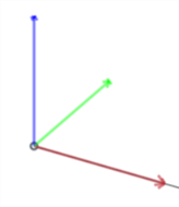
- 根據預設,會在圖形區域中顯示目前選取點的參考座標系統 (X 是紅色,Y 是綠色,Z 是藍色)。這對檢視與診斷點的 X/Y/Z 偏移是相當有用的。除非使用者另有設定,否則預設的原點會用做為參考。如果需要,可以使用替代的參考點 (例如,頂點或結合連接器)。取消核取顯示參考座標系統來停用參考座標系統的顯示。
- 核取保留點來在建立路線曲線的曲線點的相同位置上建立點。如果您要使用這些點來進行其他的模型建構,這是相當有用的。根據預設,在建立路線曲線之後會隱藏這些點。
- 按一下核取記號 (
 ) 以接受路線曲線。
- Click the Routing curve feature (
 ) on the feature toolbar to open the Routing curve dialog (first image below). The triad manipulator is visible in the graphics area and is placed on the Part Studio origin point (second image below):

The triad manipulator adjusts:
Translation across 3 axes
Rotation about 3 axes
Translation across 3 planes.
Triad manipulator origin point.
Adjusting the translation (first image below) or rotation (second image below) along one of the axes creates a solid blue line with a bar at the start. This indicates the distance or angle traveled from the start to the manipulator's origin (destination). An input box also opens where the distance or rotation can be entered numerically:


- Select the curve type:
- Interpolated spline - Creates a cubic (degree 3) interpolated spline through all points.
- Polyline - Creates line segments between each point in the curve.
- Bend radius - Adds a global Bend radius (length) value for the bend between each segment. The default value is 0 (no bend). This value can be overwritten when editing the individual point:

Interpolated spline (left); Polyline (right)
- 選擇線段。這樣可編輯曲線線段 (邊線)。當選取「線段」時,會出現代表線段的紫紅色線條。系統會將點放置在這些線段的中點。每個線段點是一個操控器,而不是控制點或頂點。

- 選擇一個線段編輯類型:
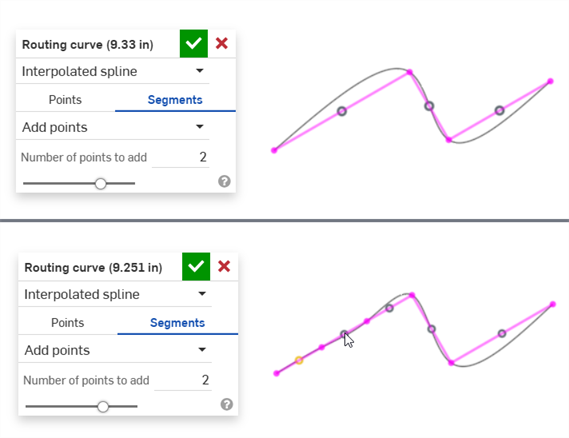
- 加入點 - 輸入要加入的點數到線段中,然後按一下線段點來選取它 (下方第一個圖片)。當點按時,會將新的點加入至線段中 (下方第二個圖片)。一條線段僅有起點與終點。加入點會將線段細分 n 次。
- 正交路徑 - 如果線段不是正交的,您可以從路徑上線段間的各種正交選項中選擇:
選擇座標系統:世界、曲線、或其他。如果選擇其他,則會顯示正交路徑座標系統欄位。在圖形區域中選擇零件的頂點或結合連接器。
- 選擇在非正交線段上的點來編輯它:
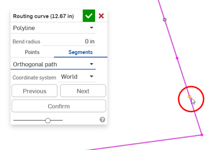
- 線段變為綠色,並顯示數個正交路徑選項之一:
![按一下 [下一個] 按鈕](Resources/Images/feature-tools/routing-curve-segment-ortho-02.png)
使用上一個和下一個按鈕來在所有可能的正交路徑選項中循環:
![按一下 [下一個] 按鈕來在正交選項間循環](Resources/Images/feature-tools/routing-curve-segment-ortho-03.png)
- 按一下 [確認] 按鈕來選擇所需的選項:
![按一下 [確認] 按鈕來做出選擇](Resources/Images/feature-tools/routing-curve-segment-ortho-04.png)
新的路徑建立:
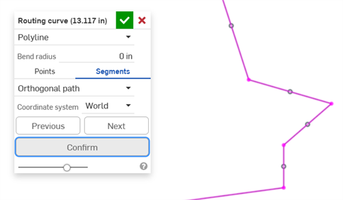
如果您 [確認] 線段然後希望選擇一個不同的正交路徑選項,請按一下「復原」圖示 (
 ) 或按下 Ctrl/Cmd+z。
可以同時為插值樣條或聚合線建立正交路徑;不過,聚合線通常更常用於管路路線中。
- 加入點 - 輸入要加入的點數到線段中,然後按一下線段點來選取它 (下方第一個圖片)。當點按時,會將新的點加入至線段中 (下方第二個圖片)。一條線段僅有起點與終點。加入點會將線段細分 n 次。
- 按一下核取記號 (
 ) 以接受路線曲線。
說明如何建立與使用路線曲線的一些範例。
若要建立一條基本的路線曲線:
-
在 Part Studio 中於特徵工具列上按一下「路線曲線」圖示 (
 ) 來開啟「路線曲線」對話方塊。
 -
選擇在拖曳軸時加入點。這樣會在每次拖曳三向操控器的平移箭頭時建立一個新的點。
-
在 3D 空間的幾個方向上拖曳操控器的平移箭頭來建立有多個點的曲線:
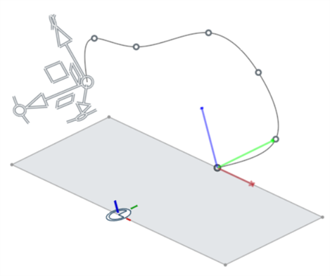
-
按一下封閉來建立封閉 (週期) 曲線:
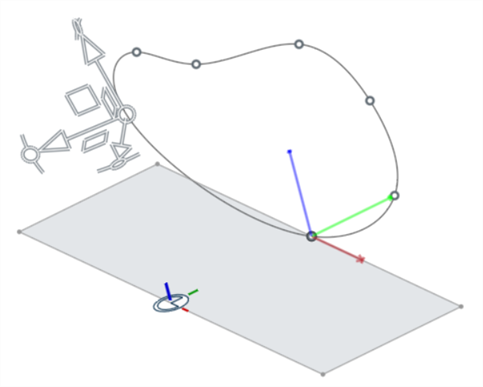
-
若要將原點調整到現有頂點或結合連接器上:
-
選擇第一個點 (除非三向操控器被移至新的位置,否則根據預設這是 Part Studio 的原點 - 請見上方的說明)。三向操控器移至第一個點上。您也可以藉查驗唯讀的點區域顯示了點 0 (第一個點) 來加以確認:
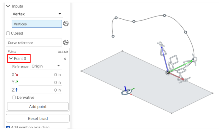
-
在路線曲線對話方塊的點參考欄位中選擇頂點。然後選擇頂點 (在下方範例中使用 Vertex of Sketch 1):
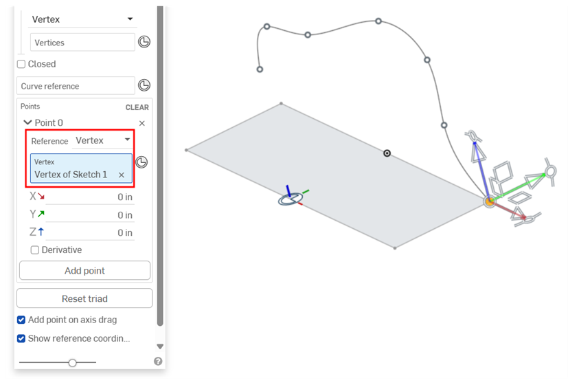
為點參考選擇一個頂點 (草圖點)
-
另一個方式是,選擇一個明確的結合連接器來使用其 Z 軸做為點參考。您也可以按一下選擇結合連接器圖示 (
 ),然後在您模型的一個位置上按一下來於建立路線曲線的過程中建立明確的結合連接器:
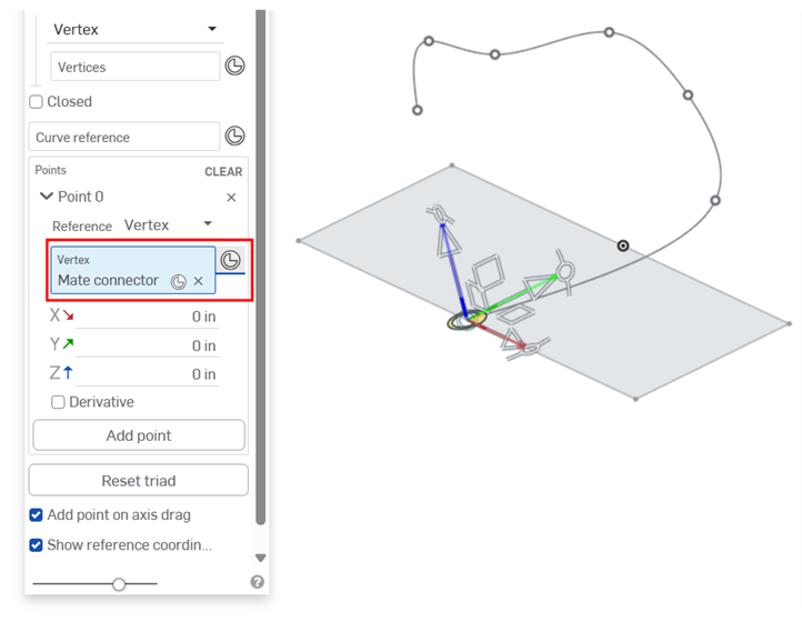
為點參考選擇一個明確的結合連接器
-
-
取消核取在拖曳軸時加入點。選擇曲線上的任何點並使用三向的平移、旋轉、和/或平面操控器來調整點在 3D 空間中的位置:
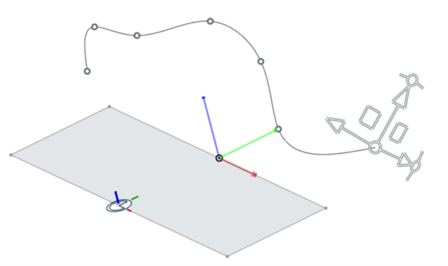
-
核取保留點 來在建立路線曲線的曲線點的相同位置上建立點 (請見下方範例)。
-
如果您犯了錯誤,請按一下「復原」圖示 (
 ) 來復原在建立路線曲線過程中的最後一個步驟。
 -
按一下核取記號 (
 ) 來接受新的路線曲線。曲線隨即建立 (下方第一個圖片),且會出現在「零件」清單中 (下方第二個圖片)。
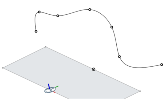
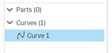
移動旋轉操控器不會建立一個新的點。同樣地,移動平面或原點操控器也不會建立一個新的點。如果沒有建立任何點,請使用這些操控器來將三向操控器移動到新的位置,可從該處開始一條曲線。在放置了一個起始點之後,可使用這些操控器來將目前選取的點移動到新的位置上。
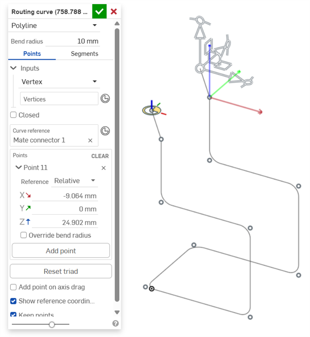
這個範例顯示如何建立路線曲線以建立椅架。
-
在 Part Studio 中,在用做為椅架左上方原點的位置建立一個結合連接器。
-
按一下特徵工具列中的路線曲線圖示 (
 ) 來開啟路線曲線對話方塊。
 -
選擇聚合線做為曲線類型,然後輸入彎折半徑值 (在下方的範例中為 10)。
-
按一下曲線參考欄位,然後選擇您之前建立的結合連接器。
-
使用 X/Y/Z 偏移一次輸入一個點,並確定每個建立點的參考是設定為相對。這樣可確保是相對於每個先前點的位置來建立偏移的 (假定您有椅架的精準尺寸)。使用加入點按鈕來在過程中加入每個點。
-
(選用) 您可以為任何點核取覆寫彎折半徑,然後輸入一個替用的彎折半徑。
-
核取保留點。
-
在完成建立椅架的曲線時,按一下核取記號 (
 ) 來接受路線曲線:
-
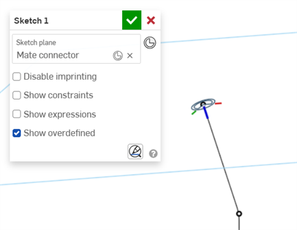
建立一個草圖,然後按一下「結合連接器」圖示 (
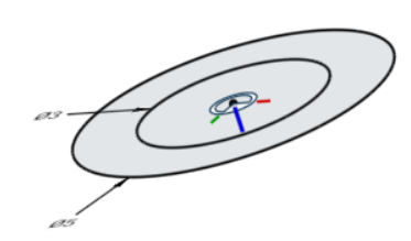
 ),接著建立一個垂直於路線路徑的隱含結合連接器 (下方第一個圖片)。繪製用於椅架的草圖形狀。在下方的範例中,建立直徑為 3mm 和 5mm 的同心圓 (下方第二個圖片):
-
使用掃掠特徵,為要掃掠的面與草圖區域選擇草圖的面,然後選擇路線曲線做為掃掠路徑:
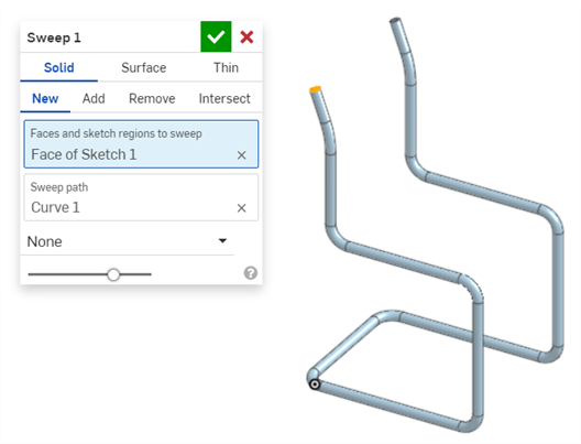
-
使用複合零件特徵,選擇路線曲線與由掃掠建立的椅架。這會會建立一個單獨的椅架零件:
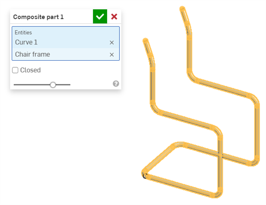
若要建立包含可建立路線曲線的點清單的 CSV 檔案:
-
開啟一個試算表程式,像是 Microsoft Excel 或 Google sheets。
-
使用分別代表 X、Y、與 Z 軸的 3 欄格式。
您稍後可以使用資料起始欄欄位來修改用於「路線曲線」對話方塊中的欄。
在每個欄位中,輸入做為從參考點 (可以是 Part Studio 原點,或使用者定義的點參考,例如現有的頂點或結合連接器) 偏移值的整數:
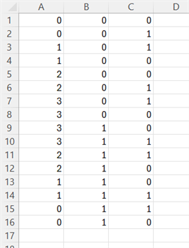
用於 CSV 檔案的 3 欄配置的範例;A = X 軸,B = Y 軸,C = Z 軸
-
將檔案以 .csv 格式儲存。
-
在一 Onshape 文件中,按一下插入新分頁圖示 (
 ),然後選擇匯入。找出您電腦中的 CSV 檔案並將其匯入至文件中。
![從「插入新分頁」功能表中選擇 [匯入]](Resources/Images/feature-tools/routing-curve-csv-01.png)
-
在 Part Studio 中於特徵工具列上按一下「路線曲線」圖示 (
 ) 來開啟「路線曲線」對話方塊。
 -
在「輸入項」之下,從「輸入類型」下拉清單中選擇 CSV 檔案:
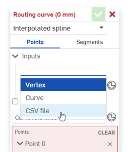
-
按一下選擇 CSV 檔案欄位來開啟選擇 CSV 檔案對話方塊。按一下對話方塊底部的匯入:
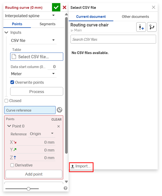
-
從您本ˋ機磁碟中找出並選擇 CSV 檔案,然後按一下開啟:
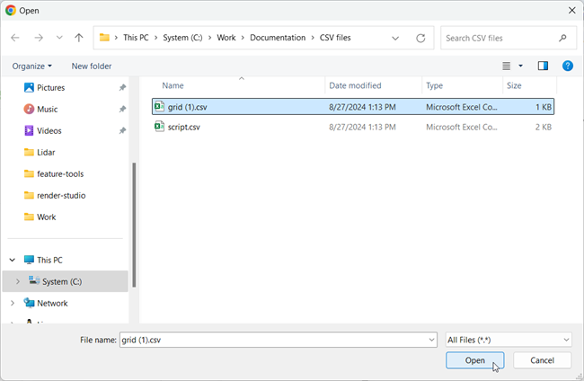
-
在匯入檔案之後,點按以選擇檔案:
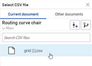
-
如果您的 X 軸欄不是從 CSV 檔案的第一個欄 (欄 0) 開始的,請在資料起始欄欄位中輸入正確的 X 軸欄。
-
在單位欄位中選擇正確的測量單位。這會決定應套用至 CSV 點清單的測量單位為何 (當將清單對應至圖形區域中時)。
-
如果在 Part Studio 中有您想要保留的預先存在點,請取消核取覆寫點。否則請將其保持為核取的。
-
按一下處理按鈕來處理 CSV 檔案。路線曲線即顯示在圖形區域中。
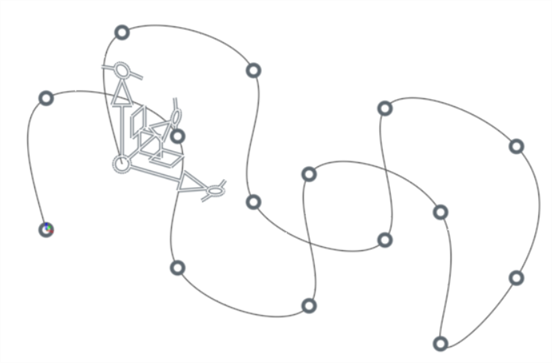
-
如在步驟部分的說明,可對路線曲線做出其他的調整。
-
當完成時,按一下核取記號 (
 ) 以接受路線曲線。
-
會在路線曲線特徵名稱中顯示路線曲線的總長度,並會在您編輯曲線時動態更新。 若要移除這個顯示,請將游標移動至核取記號的左側暫留,然後按一下「編輯」圖示 (
 ; 下方第一個圖片)。接著刪除 (#curveLength) 變數 (下方第二個圖片)。
-
無法由一個變數來驅動路線曲線。不過,將路線曲線與現有幾何中由變數驅動的點相關聯是可能的。這樣,現有幾何是覆蓋路線曲線的配置。若要建立路線曲線,選擇現有幾何的頂點、結合連接器、或曲線,然後套用一個預設的彎折半徑與偏移。
iOS 與 Android 對路線曲線特徵的支援僅限於檢視和編輯在桌面版 (瀏覽器) 平台上所建立的路線曲線。
除了曲面建構工具之外,還可使用曲線來建立曲面的基本建構塊。
這個清單是曲線特徵工具的集合,並非詳盡的清單。在操控曲線時,可能會使用其他的特徵工具。
- 草圖工具 - 草圖工具列中的工具,像是直線、轉角矩形、中心點矩形、中心點畫圓、三點畫圓、切線弧、三點定弧、樣條、點與建構線,可用來建立 Part Studio 中的草圖。
-
 螺旋線 - 使用圓錐或圓柱面、單一軸或結合連接器的 z 軸、或是環狀邊線來建立螺旋線。
 -
 3D 擬合樣條 - 建立穿過連續頂點的 3D 擬合樣條。建立列在零件清單中「曲線」之下的曲線。
 -
 投影曲線 - 建立一條來自兩個草圖投影的曲線 (「兩個草圖」選項),或是建立一條來自曲線投影至面的曲線 (「曲線到面」選項)。
 -
 橋接曲線 - 建立連接任兩個點、頂點或結合連接器的一條曲線。所產生的曲線會列於「特徵」清單與「零件」清單中。
 -
 複合曲線 - 以一條曲線來代表多條邊線。選擇多條相鄰的邊線、草圖圖元、與其他的曲線。選擇非連續的邊線會建立多條的曲線。為每條曲線做出的選擇項目必須在其頂點處交會 (曲線會列於「零件」>「曲線」清單之中)。
 -
 相交曲線 -在兩或多個曲面或面的相交處建立一條曲線。選取的項目必須是相交的。
 -
 修剪曲線 -根據距離修剪或延伸曲線,或是修剪或延伸至邊界圖元。
 -
 等傾線 - 在斜面上建立一條等傾線。等傾線會出現在面相較於其參考定義有某些傾斜的位置。所產生的等傾線會列於「特徵」清單與「零件」清單中。
 -
 偏移曲線 - 藉由在周圍面上偏移邊線來建立與延伸和/或分割新的曲線。
 -
 等參數曲線 - 建立沿面或曲面的 U 方向或 V 方向延伸的平滑曲線。
 -
 編輯曲線 - 選擇草圖圖元或曲線來套用簡化的近似、提高度數、重新定位控制曲線頂點和/或平化至任何 2D 平面來編輯現有的曲線。
 -
 路線曲線 - 建立在 3D 空間中跨越一個或多個平面的多點曲線 (路線路徑)。這對於建立管路路線、配線、以及進階曲面建立中的 NURBS 曲線是非常有用的。