 直紋曲面
直紋曲面
![]()
從一條現有邊線或草圖區域的多條邊線建立一個新的或額外的直紋曲面。
直紋曲面特徵可讓您從一條現有邊線或草圖、曲面或零件的多條邊線加入或建立新的直紋曲面。
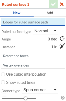
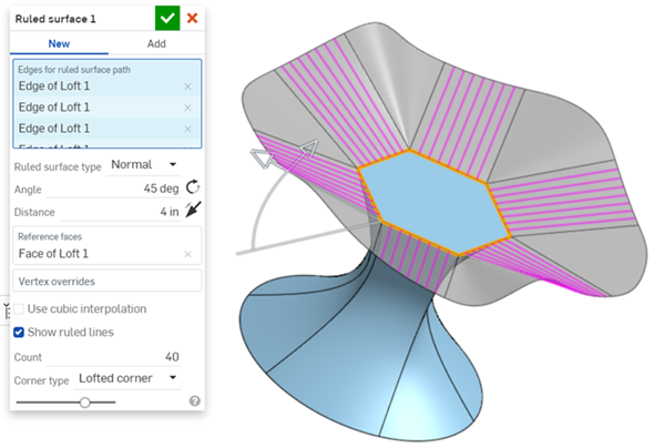
從特徵工具列中按一下「直紋曲面」特徵。選擇做為直紋曲面路徑的邊線。此處選擇的是多邊形的所有邊線。
您可以選擇不同的直紋曲面類型:「垂直」、「相切」、「與方向對齊」及「與方向形成角度」。指定直紋曲面的「角度」,然後按一下旋轉圖示來反轉方向。指定「距離」,然後按一下方向箭頭來反轉方向。在這個範例中並無法反轉方向,所以您會看到紅色的輪廓線表示這是一個錯誤。
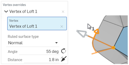
您也可以加入「頂點覆寫」。選擇一個點並從該點建立一個角度與方向。根據需要加入任意數量的頂點覆寫。
Check Use cubic interpolation to create a finer continuity between the segments of the surface. Check Show ruled lines adds lines to the ruled surface. Values are set from 1 to 100, with 40 being the default.核取「使用三次插值」可以在曲面片段間建立更精緻的連續性。核取「顯示直紋線」會將線條加入直紋曲面中,可以設定從 1 到 100 的值,預設值是 40。
選擇一個角落類型。預設是使用「轉角」。如果可能,「延伸角」會延伸角落以建立直的邊線。「提高角」會建立稍微提高的角落,「無角落」則會移除所有角落。
- Click
 .
.
- 選擇做為直紋曲面路徑的邊線,可以是單一條邊線或多條邊線。
- Specify the Ruled surface type.
- Normal - The surface is normal to the edge.
- Tangent - The surface is tangent to the edge.
- Aligned with direction - The surface is aligned to an alternate direction; for example, a ruled surface aligned to construction geometry or the edge of another object.
- Angled from direction - The surface is angled from a selected direction; for example, a ruled surface angled to the direction of construction geometry or another object.
- Specify the Angle for the surface, in relation to the selected edge(s), in degrees. Click the rotation icon to reverse the angle.
- Specify the Distance from the edge(s). Click on the arrow icon to reverse the direction.
- (Optional) Select a Reference face. This is the face used as a reference for the Ruled surface. When an edge is first selected for the Ruled surface path, one of its adjacent faces is used as the edge's reference face and is automatically added to the dialog. To select a different or additional reference face (for example, the edge's opposing face), you can select the Reference faces area of the dialog and then select the new Reference face. To delete the previously selected Reference face, click the x icon to the right of the face label.
- (Optional) select Vertex overrides. By default, the overall ruled surface definition is governed by the path created by the selected edge(s). However, you can override this behaviour and specify the ruled surface definition at any selected point, or multiple points. Select the Vertex overrides area of the dialog, and then select a vertex along the ruled surface path. You can then specify the following, for each Vertex override:
- Ruled surface type - Normal, Tangent, Aligned with direction, or Up to vertex. These are similar to the Ruled surface type above, but with the additional Up to vertex option - Up to a selected point (vertex) or Mate connector (implicit or explicit). Click the
 in order to select implicit Mate connectors. Once a Mate connector is selected, click the Mate connector icon in the dialog field to open a dialog with which to edit the Mate connector.
 - Angle - Corner angle, in degrees. Click the rotation icon to reverse the angle.
- Distance - Corner distance. Click on the arrow icon to reverse the direction.
- Ruled surface type - Normal, Tangent, Aligned with direction, or Up to vertex. These are similar to the Ruled surface type above, but with the additional Up to vertex option - Up to a selected point (vertex) or Mate connector (implicit or explicit). Click the
- (Optional) Use cubic interpolation - By default, the Ruled surface path uses linear interpolation. For finer continuity between the segments, you can select the cubic interpolation option.

兩個鏡射直紋曲面段之間的線性 (左圖) 與三次 (右圖) 插補的範例。
- (Optional) Show ruled lines - Displays ruled lines on all Ruled surfaces. The ruled lines are set per continuous path. The count can be set from 1 to 100, with 40 as a default.
- Select the Corner type. Options are:
- Spun corner (default) - Uses curved spun corners to connect adjacent surface edges, if possible.
- Extended corner - Uses extended surface lines to connect adjacent surface edges, if possible.
- Loft corner - Uses loft corners to connect adjacent surface edges, if possible.
- No corner - Omits corners between adjacent surfaces edges.
- 按一下
 。
。

從左到右:垂直、相切、與方向對齊及與方向形成角度。
如果您選擇的方向無法從其中建立零件或整個直紋曲面,會在草圖中以紅色顯示方向,表示方向是錯誤的。請為您的對齊選擇一個新的方向邊線。
如果您選擇的角度或距離會迫使直紋曲面互為相交,則會出現錯誤,且不會顯示曲面。會在「直紋曲面」對話方塊的頂部與特徵清單中以紅色顯示直紋曲面。

已套用「頂點覆寫」,其中頂點是用來操控直紋取面的角度與方向的。
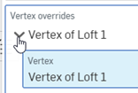
可以使用覆寫標籤左側的下拉箭頭來展開與摺疊每個「頂點覆寫」。

從左到右:轉角、延伸角、提高角與無角落。
如果無法在曲面邊線間建立角落,系統會產生一個錯誤,並顯示這個訊息:

從一個多邊形曲面向外延伸的直紋曲面
這個清單是曲面特徵工具的集合,並非詳盡的清單。在建構曲面時,可能會使用其他的特徵工具。詳細資訊請參考曲面建構。
-
 加厚 - 將厚度加入到曲面上。藉由給予曲面厚度然後將其轉換為實體,在現有零件或曲面上加入或移除材料,或是在路徑上使零件相交來建立新的零件或修改現有的零件。
 -
 封閉 - 選擇可形成實體的空間周圍的所有邊界來建立零件。使用任何互為相交或在邊界相接的曲面組與實體 (包括平面和面) 來建立一個體積。藉由加入或移除零件,或使零件相交來建立新的零件或修改現有的零件。
 -
 圓角 - 選擇「邊線」圓角來圓化尖銳的內部與外側邊線,並定義標準的固定半徑,建立更有造型的圓錐或變化。選擇性地套用「全周」圓角來在兩個對邊間建立一或多個面上無縫的混合。
 -
 面混合 - 圓滑化尖銳的連接或未連接的內部與外部面以建立面之間無縫的混合,或是將混合分離來建立新的面, 並可定義半徑或固定寬度。進一步定義混合的橫截面 (滾動球或掃出輪廓)、對稱、控制、修剪、約束與限制。
 -
 刪除面 - 從零件上移除一個幾何。選擇是否要修復周圍的面 (延伸面直至面相交),為空白加蓋,或將空白保留為開放。如果您沒有零件的參數式歷程記錄時 (通常在匯入的零件中有此狀況),此直接編輯的工具是相當方便的。
 -
 移動面 - 平移、旋轉或偏移一或多個所選的面。如果您沒有零件的參數式歷程記錄時 (通常在匯入的零件中有此狀況),此直接編輯的工具是相當方便的。
 -
 替換面 - 修剪一個面或將面延伸至一新的曲面。如果您沒有零件的參數式歷程記錄時 (通常在匯入的零件中有此狀況),此直接編輯的工具是相當方便的。
 -
 偏移曲面 - 偏移一個現有面、曲面或草圖區域來建立新的曲面。將偏移距離設定為 0 來就地產生一個副本。
 -
 邊界曲面 - 建立或新增由曲面邊界輪廓指定而來的曲面。
 -
 填補 - 定義邊界並使用邊界條件 (而不需使用參考曲面) 來細修曲面以建立一個曲面 (或從曲面建立零件)。
 -
 移動邊界 - 移動曲面的邊界線以延伸或修剪曲面。
 -
 直紋曲面 - 從一條現有邊線或草圖區域的多條邊線建立一個新的或額外的直紋曲面。
 -
 相互修剪 - 延伸兩個相鄰曲面的相交以完成對曲面的修剪。
 -
 約束曲面 - 從指定公差內的點或網格資料中選擇以建立曲面。顯示偏差並最佳化效能或平滑度。