 圓角
圓角
![]()
![]()
![]()
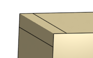
選擇「邊線」圓角來圓化尖銳的內部與外側邊線,並定義標準的固定半徑,建立更有造型的圓錐或變化。選擇性地套用「全周」圓角來在兩個對邊間建立一或多個面上無縫的混合。
快速鍵:Shift+f
「圓角」特徵工具可圓滑化尖銳的內部與外部邊線,選擇「邊線」圓角並可將邊線定義為標準的固定半徑、造型圓錐或可變圓角。
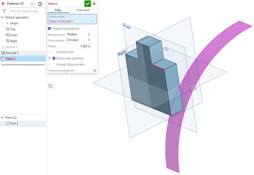
按一下 Part Studio 工具列中的「圓角」特徵。在圖形區域中選擇要建立圓角的邊線或面。保持核取「沿相切面進行」來沿著周圍邊線延伸圓角。為「測量」選擇 [寬度] 或 [半徑],然後為橫截面「控制項」選擇 [距離]、[圓錐] 或 [曲率]。輸入數值「半徑」或在圖形區域中手動調整橘色箭頭。
核取「不對稱」,然後為圓角的一邊輸入「第二半徑」。使用「反轉不對稱」箭號來將第二半徑套用至相反邊。
.核取「部分圓角」來調整沿邊線圓角的開始位置,可以在對話方塊中調整數值或在圖形區域中調整橘色箭頭。按一下「相反方向」箭頭來將圓角反轉至另一邊。核取「結束位置」來以數值或橘色箭頭調整沿邊線圓角的結束位置。
核取「可變圓角」可藉由選擇頂點來套用特定值以改變圓角的形狀與大小。
根據預設,「允許邊線溢出」是指圓角可以修改由圓角所產生面的邊線,以產生平滑連續性的曲面。取消核取可保留圓角面上的邊線,進而建立較自由流動的零件。核取「圓化圓角角落」來在兩個已圓化邊線間建立一個圓滑頂點。
按一下綠色核取記號來接受新的圓角。
- 按一下
 。
。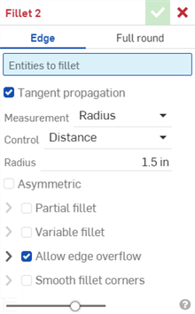
- 選擇要套用的圓角類型:邊線。
- 選擇您要建立導圓角或圓角的任何零件邊線或面。Onshape 會自動套用正確的特徵到邊線上。
- 根據預設,會核取「沿相切面進行」來將圓角延伸至相切的邊線。如果您不想將圓角延伸至相切的邊線,請取消核取。
- 選擇測量的類型,可以是:
- 半徑 - 指定圓角的半徑測量值。
- 寬度 - 指定圓角兩端間的距離 (一個固定寬度)。
- 選擇一個「控制項」類型:
- 距離 - 圓角會有您輸入半徑值的圓形邊線。如果您輸入過半徑值,Onshape 會在建立新環形圓角時記住上次為環狀圓角輸入的半徑值。
- 圓錐 - 圓角有錐形邊線,並有您輸入的半徑。可選擇性使用 Rho 值來定義圓角的樣式:
Rho 0.25 - 橢圓的曲線
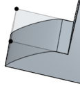
Rho 0.5 - 拋物線式曲線
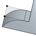
Rho 0.999 - 雙曲線式曲線
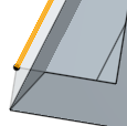
- 曲率 - 圓角與鄰近邊線的曲率配合,並有您輸入的半徑值。可選擇性使用介於 0 到 .999 之間的量值來調整相切。開啟「斑馬條紋」(從「顯示分析工具」功能表中) 來更清楚地查看相切:
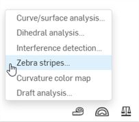
當輸入半徑值時,您也可以使用拖曳操控器 (在下圖中以箭頭表示) 來視覺呈現圓角並達到所要的預估值:
Onshape 會記住對「測量類型」與「橫截面」的選取項目,在後續的操作中打開對話方塊時即會有之前選取的選項。
- 核取「不對稱」,然後輸入「第二半徑」來在圓角邊線的另一端有不同的圓角邊線半徑值。按一下「反轉不對稱」箭號來使用圓角的另一端做為第二 (不對稱) 圓角邊線。
- 核取「部分圓角」來調整沿邊線圓角的「開始位置」。從下拉清單中選擇一個「終止類型 」:
位置 - 設定從所選邊線的一個頂點的開始位置,輸入的值代表的是百分比。
圖元 - 選擇一個平面或結合連接器來做為開始位置。或者是使用結合連接器按鈕來以隱含結合連接器設定部分圓角的位置。
偏移 - 調整部分圓角的開始處,輸入的值是從所選邊線上一頂點的距離。
按一下「相反方向」箭頭來將圓角反轉至「開始位置」的另一邊。核取「第二界限」來手動調整圓角的「終止類型」與「結束位置」。
- 核取「可變圓角」並選擇頂點來套用特定值以改變圓角的形狀與大小 (可在所有的橫截面類型中使用)。
- 選擇一個頂點 (可用的頂點會在模型中以黑色的點表示)。
- 如上所述為每個橫截面類型 (環狀、圓錐、曲率) 調整定義。
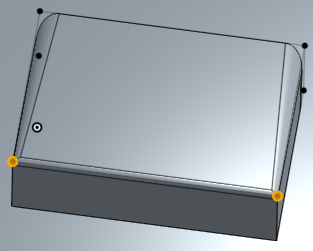
在這個範例中,環狀圓角有 8mm 的半徑 (在下圖中的上半部),而兩個橘色 (選取的) 頂點有 2mm 的半徑:
-
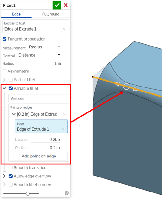
如果已套用可變圓角,您可以按一下「在邊線上加入點」選項來在現有的邊線上建立一個新的點。
-
在對話方塊的「邊線」欄位中按一下。
-
在圖形區域中選擇零件或曲面邊線。系統會以圓圈來顯示新的點,並有箭號指向兩側邊線。
-
使用箭號來沿著邊線移動點的位置,或使用「位置」欄位來輸入位置的數值。
-
在「半徑」欄位中輸入新點的半徑。
-
可選擇性地使用上述方法來在相同的邊線上加入其他的點。
-
- 如果套用可變圓角,您可以選擇核取「平滑轉換」來平滑化圓角頂點之間的線。
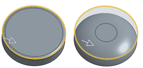
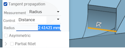
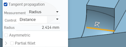
- 根據預設,會在需要的情況下讓「允許邊線溢出」的設定從圓角曲面中「刪除」相切邊線。由預設產生的邊線會嚴格限制沿著圓角邊線的圓角方向。當啟用「允許邊線溢出」時,圓角可以修改由圓角所產生面的邊線,以產生平滑連續性的曲面 (下方第一個圖片中所示)。當停用這個選項時,系統會保留已圓角面上的邊線,進而建立較自由流動的零件 (下方第二個圖片中所示)。
-
按一下「允許邊線溢出」下拉清單來開啟一個欄位,您可於其中選擇要保留的邊線。在下方的第一個圖片中,並未保留任何邊線。下方的第二個圖片則保留了鑽孔的邊線。注意到系統並未刪除沿鑽孔外緣的邊線。
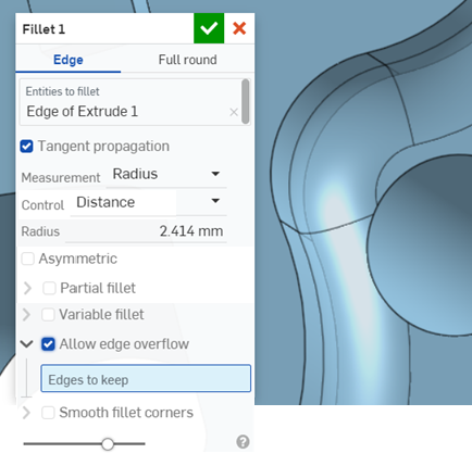
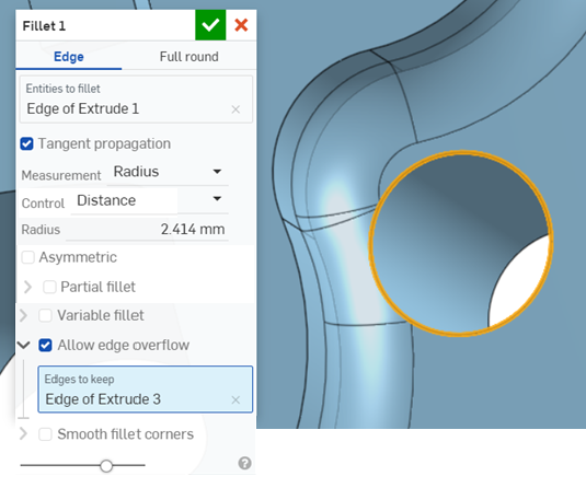
-
核取「圓化圓角角落」來在兩個已圓化邊線間建立一個圓滑頂點 (下方圖片中左下角所示)。按一下「圓化圓角角落」下拉清單來開啟一個欄位,您可於其中選擇要從圓滑化「排除的角落」(下方圖片中右下角所示;以橘色的頂點強調顯示)。
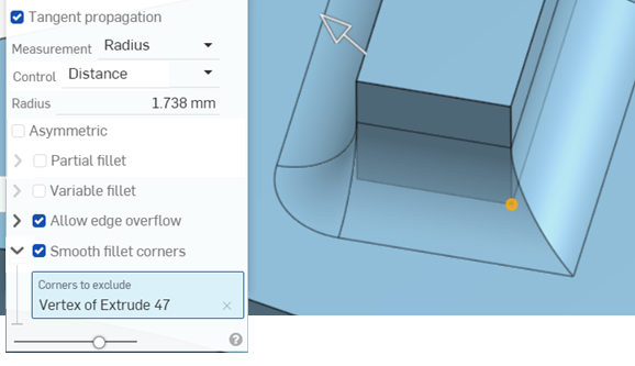
- 按一下
 。
。
當在鈑金上建立倒角時,建議使用鈑金尖角倒鈍的特徵。
開啟「斑馬條紋」或「曲率色彩對應」(在「顯示分析工具」功能表之下) 來更加善用這個功能。
選擇要於其上建立圓角的一個面:
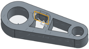
然後選擇「沿相切面進行」來將圓角延伸至相切的面:
-
核取「不對稱」
-
輸入「第二半徑」來在圓角邊線的另一端有不同的圓角邊線半徑值。
-
按一下「反轉不對稱」箭號來使用圓角的另一端做為第二 (不對稱) 圓角邊線。
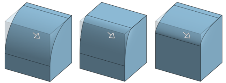
非不對稱圓角 (上圖左)、不對稱圓角 (上圖中) 與反轉後的不對稱圓角 (上圖右)
-
核取「部分圓角」。
-
從下拉清單中選擇一個「終止類型」:
位置 - 設定從所選邊線的一個頂點的開始位置,輸入的值代表的是百分比。
圖元 - 選擇一個平面或結合連接器來做為開始位置。或者是使用結合連接器按鈕來以隱含結合連接器設定部分圓角的位置。
偏移 - 調整部分圓角的開始處,輸入的值是從所選邊線上一頂點的距離。
-
按一下「相反方向」箭頭來將圓角反轉至「開始位置」的另一邊。
-
選擇性地核取「第二界限」來調整沿邊線圓角的「終止類型」或位置。
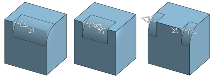
部分圓角 (上圖左)、有「結束位置」的部分圓角 (上圖中) 與在相反方向的部分圓角 (上圖右)
套用所需的圓角 (此處是 0.2 的半徑):
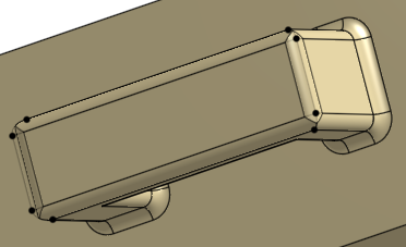
核取 [可變圓角] 並選擇所需數量的頂點 (下方選取了 2 個橘色頂點),然後為每個所選的頂點提供新的半徑 (此處是 0.8):
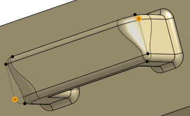
若要在邊線上加入新的點,按一下對話方塊中的 [在邊線上加入點] 按鈕:
-
在對話方塊的「邊線」欄位中按一下。
-
在圖形區域中選擇零件或曲面邊線。系統會以圓圈來顯示新的點,並有箭號指向兩側邊線。
-
使用箭號來沿著邊線移動點的位置,或使用「位置」欄位來輸入位置的數值。
-
在「半徑」欄位中輸入新點的半徑。

-
可選擇性地使用上述方法來在相同的邊線上加入其他的點。
僅當套用了可變圓角時才能使用此選項。使用「顯示分析工具」功能表中的「斑馬條紋」來查看效果。注意到條紋從一個面到另一個面如何平滑地轉換:
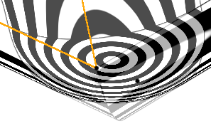
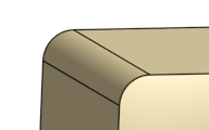
使用可變圓角:
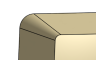
Rho 值小於 0.5 (0.1):
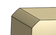
Rho 值 0.5:
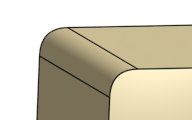
Rho 值大於 0.5 (0.999):
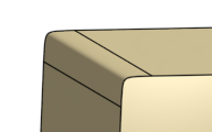
使用 0.5 的量值:
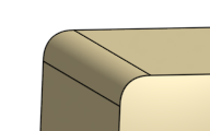
使用 0.999 的量值:
- 按一下
 。
。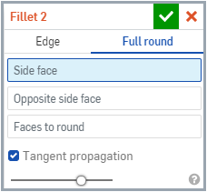
- 選擇要套用的圓角類型:全周。
- 選擇一個側面與一個反側面。
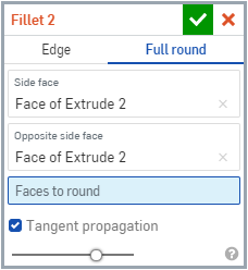
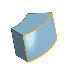
- 選擇您要用混合面來替換的一或多個面。Onshape 會自動套用正確的特徵,以建立沒有任何接縫的全周圓角。
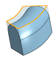
- 根據預設,會核取「沿相切面進行」來將圓角延伸至相切的邊線。如果您不想將圓角延伸至相切的邊線,請取消核取。
- 按一下
 。
。
您無法一次將全周圓角套用至多個非連續的面上。
這個清單是曲面特徵工具的集合,並非詳盡的清單。在建構曲面時,可能會使用其他的特徵工具。詳細資訊請參考曲面建構。
-
 加厚 - 將厚度加入到曲面上。藉由給予曲面厚度然後將其轉換為實體,在現有零件或曲面上加入或移除材料,或是在路徑上使零件相交來建立新的零件或修改現有的零件。
 -
 封閉 - 選擇可形成實體的空間周圍的所有邊界來建立零件。使用任何互為相交或在邊界相接的曲面組與實體 (包括平面和面) 來建立一個體積。藉由加入或移除零件,或使零件相交來建立新的零件或修改現有的零件。
 -
 圓角 - 選擇「邊線」圓角來圓化尖銳的內部與外側邊線,並定義標準的固定半徑,建立更有造型的圓錐或變化。選擇性地套用「全周」圓角來在兩個對邊間建立一或多個面上無縫的混合。
 -
 面混合 - 圓滑化尖銳的連接或未連接的內部與外部面以建立面之間無縫的混合,或是將混合分離來建立新的面, 並可定義半徑或固定寬度。進一步定義混合的橫截面 (滾動球或掃出輪廓)、對稱、控制、修剪、約束與限制。
 -
 刪除面 - 從零件上移除一個幾何。選擇是否要修復周圍的面 (延伸面直至面相交),為空白加蓋,或將空白保留為開放。如果您沒有零件的參數式歷程記錄時 (通常在匯入的零件中有此狀況),此直接編輯的工具是相當方便的。
 -
 移動面 - 平移、旋轉或偏移一或多個所選的面。如果您沒有零件的參數式歷程記錄時 (通常在匯入的零件中有此狀況),此直接編輯的工具是相當方便的。
 -
 替換面 - 修剪一個面或將面延伸至一新的曲面。如果您沒有零件的參數式歷程記錄時 (通常在匯入的零件中有此狀況),此直接編輯的工具是相當方便的。
 -
 偏移曲面 - 偏移一個現有面、曲面或草圖區域來建立新的曲面。將偏移距離設定為 0 來就地產生一個副本。
 -
 邊界曲面 - 建立或新增由曲面邊界輪廓指定而來的曲面。
 -
 填補 - 定義邊界並使用邊界條件 (而不需使用參考曲面) 來細修曲面以建立一個曲面 (或從曲面建立零件)。
 -
 移動邊界 - 移動曲面的邊界線以延伸或修剪曲面。
 -
 直紋曲面 - 從一條現有邊線或草圖區域的多條邊線建立一個新的或額外的直紋曲面。
 -
 相互修剪 - 延伸兩個相鄰曲面的相交以完成對曲面的修剪。
 -
 約束曲面 - 從指定公差內的點或網格資料中選擇以建立曲面。顯示偏差並最佳化效能或平滑度。
選擇「邊線」圓角來圓化尖銳的內部與外側邊線,並定義標準的固定半徑,建立更有造型的圓錐或變化。選擇性地套用「全周」圓角來在兩個對邊間建立一或多個面上無縫的混合。
- 輕觸「圓角」工具圖示 (
 )。
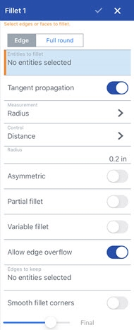
)。
- 選擇 [邊線]。
- 選擇您要建立導圓角或圓角的任何零件邊線或面。Onshape 會自動套用正確的特徵到邊線上。
- 根據預設,會核取沿相切面進行來將圓角延伸至相切的邊線。如果您不想將圓角延伸至相切的邊線,請關閉此選項。
- 選擇測量的類型,可以是:
- 半徑 - 指定圓角的半徑測量值。
- 寬度 - 指定圓角兩端間的距離 (一個固定寬度)。
- Select a Control type:
Distance - Fillet has a circular edge with the radius value you enter
Conic - Fillet has a conical edge with the radius value you enter and optionally a Rho value to define the style of the fillet:
Rho 0.25 - Elliptical curve

Rho 0.5 - Parabolic curve

Rho 0.999 - Hyperbolic curve

- 曲率 - 圓角與鄰近邊線的曲率配合,並有您輸入的半徑值。可選擇性使用介於 0 到 .999 之間的量值來調整相切。
當輸入半徑值時,您也可以使用拖曳操控器 (在下圖中以箭頭表示) 來視覺呈現圓角並達到所要的預估值:

- 開啟「不對稱」,然後輸入「第二半徑」來在圓角邊線的另一端有不同的圓角邊線半徑值。按一下「反轉不對稱」箭號來使用圓角的另一端做為第二 (不對稱) 圓角邊線。
- 核取「部分圓角」來調整沿邊線圓角的「開始位置」。從下拉清單中選擇一個「終止類型 」:
位置 - 設定從所選邊線的一個頂點的開始位置,輸入的值代表的是百分比。
圖元 - 選擇一個平面或結合連接器來做為開始位置。或者是使用結合連接器按鈕來以隱含結合連接器設定部分圓角的位置。
偏移 - 調整部分圓角的開始處,輸入的值是從所選邊線上一頂點的距離。
按一下「相反方向」箭頭來將圓角反轉至「開始位置」的另一邊。核取「第二界限」來手動調整圓角的「終止類型」與「結束位置」。
- 開啟「可變圓角」並選擇頂點來套用特定值以改變圓角的形狀與大小 (可在所有的橫截面類型中使用)。
- 選擇一個頂點 (可用的頂點會在模型中以黑色的點表示)。
- 如上所述為每個橫截面類型 (環狀、圓錐、曲率) 調整定義。
在這個範例中,環狀圓角有 8mm 的半徑 (在下圖中的上半部),而兩個橘色 (選取的) 頂點有 2mm 的半徑:

-
如果已套用可變圓角,您可以按一下「邊線上的點」選項來在現有的邊線上建立一個新的點。
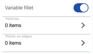
-
在下一個對話方塊中按一下 [在邊線上加入點] 按鈕。
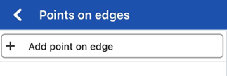
-
選擇「邊線」欄位,然後在圖形區域中選擇零件或曲面邊線。系統會以圓圈來顯示新的點,並有箭號指向兩側邊線。
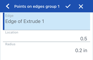
-
使用箭號來沿著邊線移動點的位置,或使用「位置」欄位來輸入位置的數值。
-
在「半徑」欄位中輸入新點的半徑。
-
可選擇性地使用上述方法來在相同的邊線上加入其他的點。
-
- 如果已套用可變圓角,您可以選擇性選取「平滑轉換」 來平滑化圓角頂點之間的線。
- 根據預設,會在需要的情況下讓「允許邊線溢出」的設定從圓角曲面中「刪除」相切邊線。由預設產生的邊線會嚴格限制沿著圓角邊線的圓角方向。當啟用「允許邊線溢出」時,圓角可以修改由圓角所產生面的邊線,以產生平滑連續性的曲面 (下方第一個圖片中所示)。當停用這個選項時,系統會保留已圓角面上的邊線,進而建立較自由流動的零件 (下方第二個圖片中所示)。
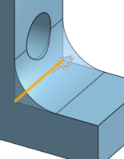
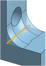
-
按一下 [保留的邊線] 然後在圖形區域中選擇邊線。在下方的第一個圖片中,並未保留任何邊線。下方第二個圖片中則保留了鑽孔的邊線。注意到系統並未刪除沿鑽孔外緣的邊線。
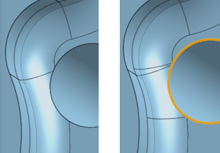
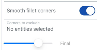
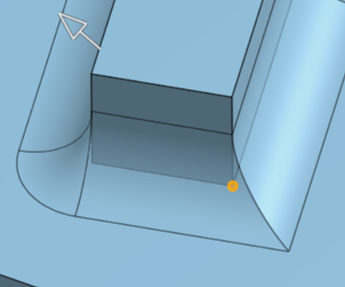
- 啟用「圓化圓角角落」來在兩個已圓化邊線間建立一個圓滑頂點 (下方圖片中左下角所示)。您可以選擇任何要從圓滑化中「排除的角落」(下方圖片中右下角所示;以橘色的頂點強調顯示)。
- 輕觸核取記號。
當在鈑金上建立倒角時,建議使用鈑金尖角倒鈍的特徵。
選擇要於其上建立圓角的一個面:

然後選擇「沿相切面進行」來將圓角延伸至相切的面:

-
開啟「不對稱」。
-
輸入「第二半徑」來在圓角邊線的另一端有不同的圓角邊線半徑值。
-
按一下「反轉不對稱」箭號來使用圓角的另一端做為第二 (不對稱) 圓角邊線。

非不對稱圓角 (上圖左)、不對稱圓角 (上圖中) 與反轉後的不對稱圓角 (上圖右)
-
開啟「部分圓角」。
-
沿邊線調整圓角的「開始位置」。
-
按一下「相反方向」箭頭來將圓角反轉至「開始位置」的另一邊。如果需要,開啟「結束位置」來調整沿邊線圓角的結束位置。

部分圓角 (上圖左)、有「結束位置」的部分圓角 (上圖中) 與在相反方向的部分圓角 (上圖右)
套用所需的圓角 (此處是 0.2 的半徑):

核取 [可變圓角] 並選擇所需數量的頂點 (下方選取了 2 個橘色頂點),然後為每個所選的頂點提供新的半徑 (此處是 0.8):

如果已套用可變圓角,您可以按一下「邊線上的點」選項來在現有的邊線上建立一個新的點。

-
在下一個對話方塊中按一下 [在邊線上加入點] 按鈕。

-
選擇「邊線」欄位,然後在圖形區域中選擇零件或曲面邊線。系統會以圓圈來顯示新的點,並有箭號指向兩側邊線。

-
使用箭號來沿著邊線移動點的位置,或使用「位置」欄位來輸入位置的數值。
-
在「半徑」欄位中輸入新點的半徑。
-
可選擇性地使用上述方法來在相同的邊線上加入其他的點。
僅當套用了可變圓角時才能使用此選項。開啟「斑馬條紋」來查看效果 (您可以在「視角」立方體功能表的「曲率視覺化」功能表之下找到「斑馬條紋」)。注意到條紋從一個面到另一個面如何平滑地轉滑:


使用可變圓角

Rho 值小於 0.5 (0.1):

Rho 值 0.5:

Rho 值大於 0.5 (0.999):

使用 0.5 的量值:

使用 0.999 的量值:

- 輕觸「圓角」工具圖示 (
 )。
)。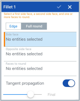
- 選擇 [全周]。
- 選擇一個側面與一個反側面。
- 選擇您要用混合面來替換的一或多個面。Onshape 會自動將正確的特徵套用至邊線上。
- 根據預設,會核取沿相切面進行來將圓角延伸至相切的邊線。如果您不想將圓角延伸至相切的邊線,請關閉此選項。
- 輕觸核取記號。
您無法一次將全周圓角套用至多個非連續的面上。
選擇「邊線」圓角來圓化尖銳的內部與外側邊線,並定義標準的固定半徑,建立更有造型的圓錐或變化。選擇性地套用「全周」圓角來在兩個對邊間建立一或多個面上無縫的混合。
- 輕觸圓角工具。


- 選擇您要建立導圓角或圓角的任何零件邊線或面。Onshape 會自動套用正確的特徵到邊線上。
- 根據預設,會核取沿相切面進行來將圓角延伸至相切的邊線。如果您不想將圓角延伸至相切的邊線,請關閉此選項。
- 選擇測量的類型,可以是:
- 半徑 - 指定圓角的半徑測量值。
- 寬度 - 指定圓角兩端間的距離 (一個固定寬度)。
- Select a cross section type:
Circular - Fillet has a circular edge with the radius value you enter
Conic - Fillet has a conical edge with the radius value you enter and optionally a Rho value to define the style of the fillet:
Rho 0.25 - Elliptical curve

Rho 0.5 - Parabolic curve

Rho 0.999 - Hyperbolic curve

- 曲率 - 圓角與鄰近邊線的曲率配合,並有您輸入的半徑值。可選擇性使用介於 0 到 .999 之間的量值來調整相切。
當輸入半徑值時,您也可以使用拖曳操控器 (在下圖中以箭頭表示) 來視覺呈現圓角並達到所要的預估值:

- 開啟「不對稱」,然後輸入「第二半徑」來在圓角邊線的另一端有不同的圓角邊線半徑值。按一下「反轉不對稱」箭號來使用圓角的另一端做為第二 (不對稱) 圓角邊線。
- 核取「部分圓角」來調整沿邊線圓角的「開始位置」。從下拉清單中選擇一個「終止類型 」:
位置 - 設定從所選邊線的一個頂點的開始位置,輸入的值代表的是百分比。
圖元 - 選擇一個平面或結合連接器來做為開始位置。或者是使用結合連接器按鈕來以隱含結合連接器設定部分圓角的位置。
偏移 - 調整部分圓角的開始處,輸入的值是從所選邊線上一頂點的距離。
按一下「相反方向」箭頭來將圓角反轉至「開始位置」的另一邊。核取「第二界限」來手動調整圓角的「終止類型」與「結束位置」。
- 開啟「可變圓角」並選擇頂點來套用特定值以改變圓角的形狀與大小 (可在所有的橫截面類型中使用)。
- 選擇一個頂點 (可用的頂點會在模型中以黑色的點表示)。
- 如上所述為每個橫截面類型 (環狀、圓錐、曲率) 調整定義。
在這個範例中,環狀圓角有 8mm 的半徑 (在下圖中的上半部),而兩個橘色 (選取的) 頂點有 2mm 的半徑:

-
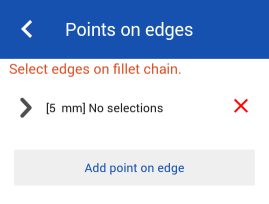
如果已套用可變圓角,您可以按一下「在邊線上加入點」選項來在現有的邊線上建立一個新的點。
-
在對話方塊的「邊線」欄位中按一下。
-
在圖形區域中選擇零件或曲面邊線。系統會以圓圈來顯示新的點,並有箭號指向兩側邊線。
-
使用箭號來沿著邊線移動點的位置,或使用「位置」欄位來輸入位置的數值。
-
在「半徑」欄位中輸入新點的半徑。
-
可選擇性地使用上述方法來在相同的邊線上加入其他的點。
-
- 如果套用可變圓角,您可以選擇核取「平滑轉換」來平滑化圓角頂點之間的線。
- 根據預設,會在需要的情況下讓「允許邊線溢出」的設定從圓角曲面中「刪除」相切邊線。由預設產生的邊線會嚴格限制沿著圓角邊線的圓角方向。當啟用「允許邊線溢出」時,圓角可以修改由圓角所產生面的邊線,以產生平滑連續性的曲面 (下方第一個圖片中所示)。當停用這個選項時,系統會保留已圓角面上的邊線,進而建立較自由流動的零件 (下方第二個圖片中所示)。


-
按一下 [保留的邊線] 然後在圖形區域中選擇邊線。在下方的第一個圖片中,並未保留任何邊線。下方第二個圖片中則保留了鑽孔的邊線。注意到系統並未刪除沿鑽孔外緣的邊線。

- 啟用「圓化圓角角落」來在兩個已圓化邊線間建立一個圓滑頂點 (下方圖片中左下角所示)。您可以選擇任何要從圓滑化中「排除的角落」(下方圖片中右下角所示;以橘色的頂點強調顯示)。
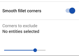

- 輕觸核取記號。
當在鈑金上建立倒角時,建議使用鈑金尖角倒鈍的特徵。
選擇要於其上建立圓角的一個面:

然後選擇「沿相切面進行」來將圓角延伸至相切的面:

-
開啟「不對稱」。
-
輸入「第二半徑」來在圓角邊線的另一端有不同的圓角邊線半徑值。
-
按一下「反轉不對稱」箭號來使用圓角的另一端做為第二 (不對稱) 圓角邊線。

非不對稱圓角 (上圖左)、不對稱圓角 (上圖中) 與反轉後的不對稱圓角 (上圖右)
-
開啟「部分圓角」。
-
沿邊線調整圓角的「開始位置」。
-
按一下「相反方向」箭頭來將圓角反轉至「開始位置」的另一邊。如果需要,開啟「結束位置」來調整沿邊線圓角的結束位置。

部分圓角 (上圖左)、有「結束位置」的部分圓角 (上圖中) 與在相反方向的部分圓角 (上圖右)
套用所需的圓角 (此處是 0.2 的半徑):

核取 [可變圓角] 並選擇所需數量的頂點 (下方選取了 2 個橘色頂點),然後為每個所選的頂點提供新的半徑 (此處是 0.8):

若要在邊線上加入新的點,按一下對話方塊中的 [在邊線上加入點] 按鈕:
-
在對話方塊的「邊線」欄位中按一下。
-
在圖形區域中選擇零件或曲面邊線。系統會以圓圈來顯示新的點,並有箭號指向兩側邊線。
-
使用箭號來沿著邊線移動點的位置,或使用「位置」欄位來輸入位置的數值。
-
在「半徑」欄位中輸入新點的半徑。
-
可選擇性地使用上述方法來在相同的邊線上加入其他的點。
僅當套用了可變圓角時才能使用此選項。開啟「斑馬條紋」來查看效果 (可以在「視角」立方體功能表的「曲率視覺化」功能表之下找到「斑馬條紋」)。注意到條紋從一個面到另一個面如何平滑地轉滑:


使用可變圓角:

Rho 值小於 0.5 (0.1):

Rho 值 0.5:

Rho 值大於 0.5 (0.999):

使用 0.5 的量值:

使用 0.999 的量值:

- 輕觸圓角工具。

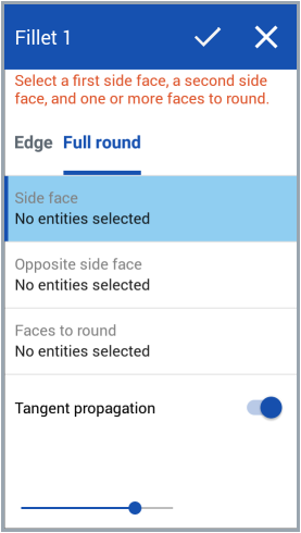
- 選擇 [全周]。
- 選擇一個側面與一個反側面。
- 選擇您要用混合面來替換的一或多個面。Onshape 會自動將正確的特徵套用至邊線上。
- 根據預設,會核取沿相切面進行來將圓角延伸至相切的邊線。如果您不想將圓角延伸至相切的邊線,請關閉此選項。
- 輕觸核取記號。
您無法一次將全周圓角套用至多個非連續的面上。
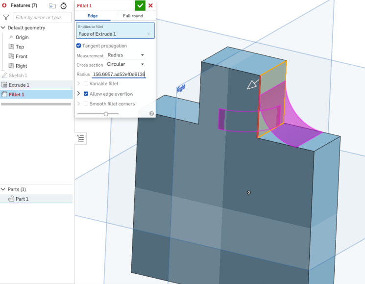
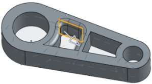
建立圓角時,如果為圓角指定的規格對所選邊線或面過大,可能會發生錯誤。在這種狀況下,Onshape 會視覺顯示特定的圓角以幫助診斷特徵的失敗原因:
