 約束曲面
約束曲面
![]()
![]()
![]()
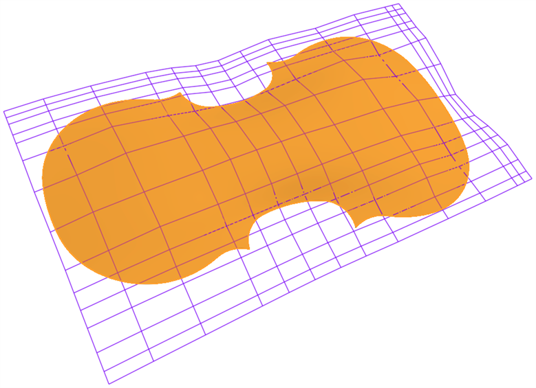
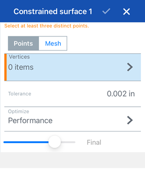
從指定公差內的點或網格資料中選擇以建立曲面。顯示偏差並最佳化效能或平滑度。
Similar to a weave of cloth, every surface is roughly rectangular. Surfaces have three directions: U, V, and Normal. The Boundary surface profiles U and V represent the X and Y directions of the surface, respectively.
- 按一下「約束曲面」圖示 (
 )。
)。
- 選擇要根據點或是網格資料來定義曲面。
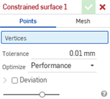
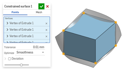
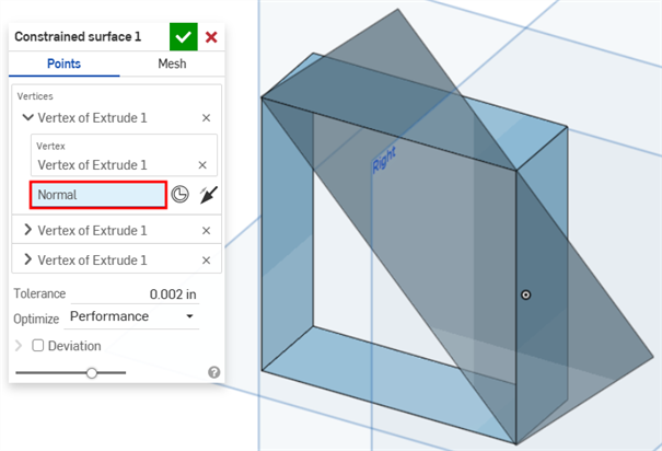
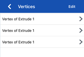
- 點 - 選擇定義曲面的頂點。系統會建立垂直於頂點的曲面。若要變更曲面的方位,在對話方塊中按一下頂點來顯示其他的選項:
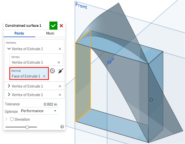
- 點按垂直欄位來加以選取,然後選擇要從模型建立曲面的方向。
- 按一下結合連接器按鈕來選擇結合連接器。
- 按一下反轉垂直按鈕來切換方位。
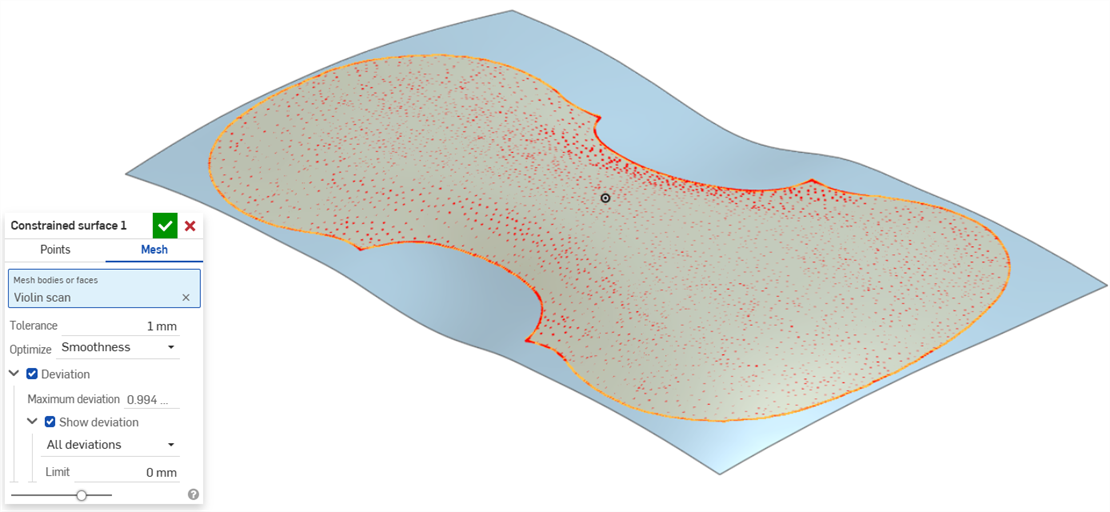
- 網格 - 選擇網格本體或面來定義曲面。
- 點 - 選擇定義曲面的頂點。系統會建立垂直於頂點的曲面。若要變更曲面的方位,在對話方塊中按一下頂點來顯示其他的選項:
- 設定建立曲面時允許的公差。公差越大,所產生的曲面就越簡單與越大。
- 按一下最佳化下拉清單,然後選擇要為效能或是平滑度最佳化。
- 效能 - 較快的效能但產生較低品ˋ質的曲面。
- 平滑度 - 通常會產生有較低曲率的較高ˋ品質曲面,但是效能較慢且有更多的控制點。
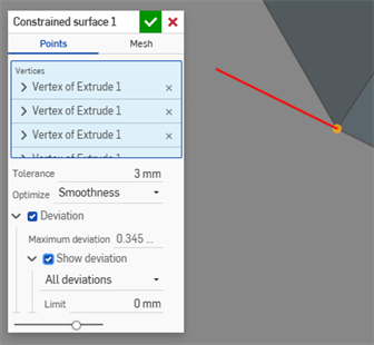
- 按一下偏差核取方塊來檢視原始點/網格與所建立曲面間的最大偏差。
- 按一下顯示偏差核取方塊來在模型上顯示最大偏差或所有偏差。
- 設定顯示偏差的限制。不會在模型上顯示任何低於所輸入限制的偏差。
- 按一下
 。
。

這個清單是曲面特徵工具的集合,並非詳盡的清單。在建構曲面時,可能會使用其他的特徵工具。詳細資訊請參考曲面建構。
-
 加厚 - 將厚度加入到曲面上。藉由給予曲面厚度然後將其轉換為實體,在現有零件或曲面上加入或移除材料,或是在路徑上使零件相交來建立新的零件或修改現有的零件。
 -
 封閉 - 選擇可形成實體的空間周圍的所有邊界來建立零件。使用任何互為相交或在邊界相接的曲面組與實體 (包括平面和面) 來建立一個體積。藉由加入或移除零件,或使零件相交來建立新的零件或修改現有的零件。
 -
 圓角 - 選擇「邊線」圓角來圓化尖銳的內部與外側邊線,並定義標準的固定半徑,建立更有造型的圓錐或變化。選擇性地套用「全周」圓角來在兩個對邊間建立一或多個面上無縫的混合。
 -
 面混合 - 圓滑化尖銳的連接或未連接的內部與外部面以建立面之間無縫的混合,或是將混合分離來建立新的面, 並可定義半徑或固定寬度。進一步定義混合的橫截面 (滾動球或掃出輪廓)、對稱、控制、修剪、約束與限制。
 -
 刪除面 - 從零件上移除一個幾何。選擇是否要修復周圍的面 (延伸面直至面相交),為空白加蓋,或將空白保留為開放。如果您沒有零件的參數式歷程記錄時 (通常在匯入的零件中有此狀況),此直接編輯的工具是相當方便的。
 -
 移動面 - 平移、旋轉或偏移一或多個所選的面。如果您沒有零件的參數式歷程記錄時 (通常在匯入的零件中有此狀況),此直接編輯的工具是相當方便的。
 -
 替換面 - 修剪一個面或將面延伸至一新的曲面。如果您沒有零件的參數式歷程記錄時 (通常在匯入的零件中有此狀況),此直接編輯的工具是相當方便的。
 -
 偏移曲面 - 偏移一個現有面、曲面或草圖區域來建立新的曲面。將偏移距離設定為 0 來就地產生一個副本。
 -
 邊界曲面 - 建立或新增由曲面邊界輪廓指定而來的曲面。
 -
 填補 - 定義邊界並使用邊界條件 (而不需使用參考曲面) 來細修曲面以建立一個曲面 (或從曲面建立零件)。
 -
 移動邊界 - 移動曲面的邊界線以延伸或修剪曲面。
 -
 直紋曲面 - 從一條現有邊線或草圖區域的多條邊線建立一個新的或額外的直紋曲面。
 -
 相互修剪 - 延伸兩個相鄰曲面的相交以完成對曲面的修剪。
 -
約束曲面 - 從指定公差內的點或網格資料中選擇以建立曲面。顯示偏差並最佳化效能或平滑度。
- 輕觸「約束曲面」圖示 ()。
- 選擇要根據點或是網格資料來定義曲面。
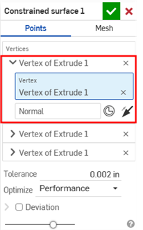
- 點 - 選擇定義曲面的頂點。系統會建立垂直於所選頂點的曲面。若要變更曲面的方位,輕觸「頂點」,然後輕觸頂點 (下方第一個圖片) 來顯示「頂點群組」的其他選項 (下方第二個圖片):
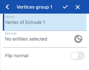
- 輕觸垂ˊ直欄位來加以選取,然後選擇要從模型建立曲面的方向。
- 輕觸結合連接器按鈕來選擇結合連接器。
- 切換開啟反轉垂直來切換方位。
- 網格 - 選擇網格本體或面來定義曲面。
- 點 - 選擇定義曲面的頂點。系統會建立垂直於所選頂點的曲面。若要變更曲面的方位,輕觸「頂點」,然後輕觸頂點 (下方第一個圖片) 來顯示「頂點群組」的其他選項 (下方第二個圖片):
- 設定建立曲面時允許的公差。公差越大,所產生的曲面就越簡單與越大。
- 輕觸最佳化下拉清單,然後選擇要為效能或是平滑度最佳化。
- 效能 - 較快的效能但產生較低品ˋ質的曲面。
- 平滑度 - 通常會產生有較低曲率的較高ˋ品質曲面,但是效能較慢且有更多的控制點。
- 切換開啟偏差來檢視原始點/網格與所建立曲面間的最大偏差。
- 切換開啟顯示偏差來顯示「偏差類型」。輕觸然後選擇在模型上的最大偏差或所有偏差。
- 設定顯示偏差的限制。不會在模型上顯示任何低於所輸入限制的偏差。
- 輕觸核取記號。
Android 對約束曲面特徵的支援僅限於顯示與編輯現有的曲面。僅能在桌面版 (瀏覽器) 平台上建立約束曲面。無法在 Android 平台上建立約束曲面。