疊層拉伸
使用輪廓 (草圖區域或草圖曲線) 與選用的導引曲線來定義平滑轉換的形狀。建立零件或曲面,或是修改現有的零件或曲面。
![關閉](../Skins/Default/Stylesheets/Images/transparent.gif)
![影片範例圖示](Resources/Images/icons/help-video@2x.png)
![關閉](../Skins/Default/Stylesheets/Images/transparent.gif)
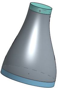
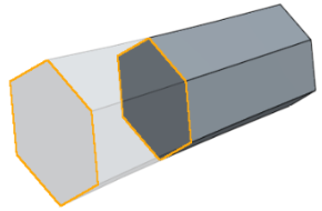
A Loft feature creates a solid or a surface with a smooth transition between its profiles. It is a powerful tool that can create more complex geometry.
Depending on the selection, a Loft feature creates a solid part, surface, or thin solid.
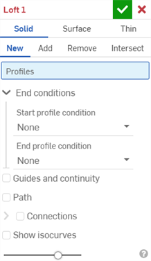
Start a new Loft feature from the feature toolbar.
Select the Profiles for the loft. A loft requires at least two profiles but can span across more when necessary. This example uses sketches, but planar or non-planar faces or surfaces, as well as a single point, may also serve as Loft profiles. It is important to select the profiles in sequential order.
If profiles are out of order, click the Reorder items button to enable drag handles. Click Done reordering once complete.
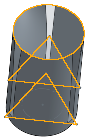
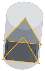
For best results, each profile in the loft should contain the same number of vertices. Consider a loft between a rectangle and a circle. One profile has four vertices, while the other has none. Onshape must assume how the two profiles are connected. This assumption can lead to undesirable twisting of the loft. To overcome this, create a profile with the same number of vertices. In this example, the split command separates a circular sketch into four segments. Use the new sketch in place of the circular face to make a smoother transition between the profiles.
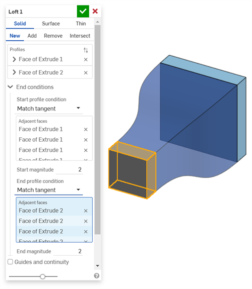
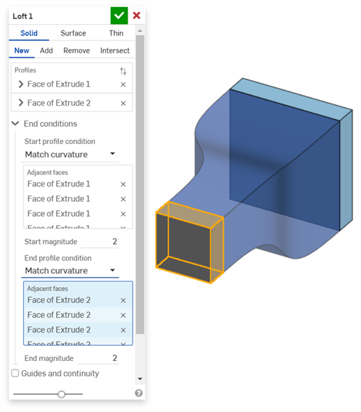
Select Start and End profile conditions for finer control of a Loft’s shape. Normal to profile and Tangent to profile work for all profile types, but Match tangent and Match curvature require adjacent faces to define the condition. Adjust the magnitude as needed.
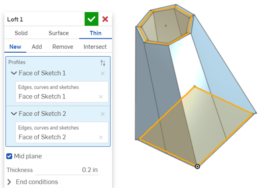
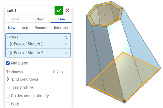
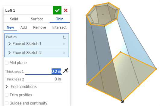
Use the same process to create a Surface or Thin loft. For a Thin loft, specify the thickness on either side of the profile. Alternatively, enable the Mid plane option to center it on the profile.
Loft profiles cannot contain multiple contours. Ensure all loft profiles are single contours. When a profile with additional contours is selected, Onshape displays it in red, indicating it is unsuitable for a Loft feature.
![關閉](../Skins/Default/Stylesheets/Images/transparent.gif)
- 按一下
。
- 選擇 [實體] 建立類型。
- 指定「結果」操作類型:
- 新 - 建立新的實體。
- 加入 - 加入至現有的實體。
- Remove - Subtract from an existing solid.
- Intersect - Keep only the intersection of two (or more) solids.
- 選擇輪廓 (一個區域、面、邊線或點), 然後 (選用) 選擇橫截面 (依疊層拉伸方向的順序) ,最後選擇結束輪廓 (區域、面、邊線或點)。
若要以單一連續來選擇一組相切連接的曲線,在對話方塊中按一下所要選取項目旁的箭頭以展開選取項目的欄位 (藍色的欄位表示是使用中的)。選擇多條曲線來建立多重的選擇。
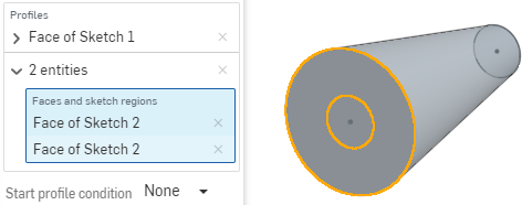
For example: To select both circles in the end loft position, select the first circle, then click in the field where the first selection appears and then click the second selection:
- To refine the shape further, select a Start and/or End Profile condition to define the derivative constraints on the start and end profiles:
- Normal to profile - Causes the loft to touch the profile with tangents parallel to the profile's normal
- Tangent to profile - Causes the loft to touch the profile tangent to the profile plane.
- Match tangent - Causes the loft to match the tangents of model faces adjacent to the profile face (if available). Optionally, when selected, the Adjacent faces field is enabled. Pick any face in which underlying geometry is coincident with at least one profile part's curve (the face and edge do not need to intersect or be part of the same part).
- Match curvature - Causes the loft to match the curvature of model faces adjacent to the profile face (if available). Optionally, when selected, the Adjacent faces field is enabled. Pick any face in which underlying geometry is coincident with at least one profile part's curve (the face and edge do not need to intersect or be part of the same part).
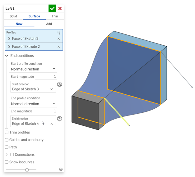
- Normal direction - Causes the loft profile to be normal to a selected direction, for example, a line or mate connector. Optionally, enter a positive or negative Magnitude value to adjust the surface shape according to one profile or another.
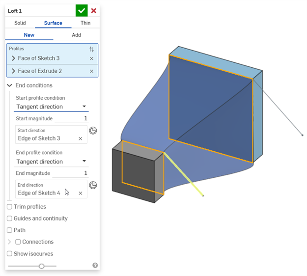
- Tangent direction - Causes the loft profile to be tangent to a selected direction, for example, a line or mate connector. Optionally, enter a positive or negative Magnitude value to adjust the surface shape according to one profile or another.
- Normal to profile - Causes the loft to touch the profile with tangents parallel to the profile's normal
- 選擇性地使用一或多條導引曲線以供疊層拉伸進行;導引曲線不一定要接觸輪廓的外側,只要相交即可。
- Check the Guides and continuity box.
- 選擇要用來做為導引的一或多條曲線。
- (Optional) To select tangentially connected curves as a single guide, click the down arrow next to the selected guide to open the field for more selections.
- Make additional selections:
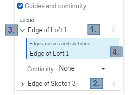
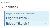
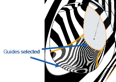
1 and 2: Each of these is a single guide selection (“Edge of Loft 1” and “Edge of Sketch 3”).
3:按一下導引名稱旁的箭頭來展開欄位。
4:藍色的強調顯示表示欄位是使用中的。在這個時候,您可以選擇更多相鄰的曲線來建立多重的導引選取項目。
- (Optional) For further definition, use the Continuity condition on the guide. Continuity can be:
- Normal to guide - Causes the loft to touch the guide with tangents parallel to the guide's normal.
- Tangent to guide - Causes the loft to touch the guide with tangents on the guide's plane.
- Match tangent - Causes the loft to match the face tangent of the guides adjacent to the profile.
- Match curvature - Causes the curvature of the loft faces to match the curvature of the guides adjacent to the profile.
Make sure that your sketch is consistent with what you are selecting, if the sketch is inconsistent with Match tangent and it is selected, the loft will fail. The same is true for Match curvature.
- Make additional selections:
- 要建立等同中心線,請選擇一條路徑路徑來讓疊層拉伸進行 (並產生沿著路徑的居間剖面來讓疊層拉伸參考)。
- 按一下「路徑」旁的方塊。
- Select edges, curves, and sketches to act as the path (centerline guide) of the loft.
- 指定沿路徑要使用的剖面數量 (居間剖面數)。使用的剖面數量越多,路徑會更精準地進行。
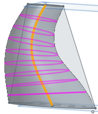
For example: Straight line selected as the path, section count = 3
選取樣條做為路徑,剖面數量 = 10
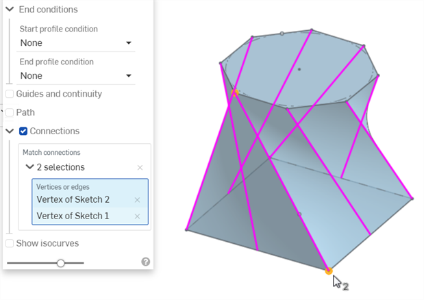
- 選擇性使用,選擇連接來對所產生曲面的扭轉有更多的控制。如果有導引線,會被用於對齊上。如果沒有,Onshape 會約計現有頂點間的鄰近性。最佳的方式是在每個輪廓上至少有兩個頂點,並使用相配的頂點來控制扭轉。
- 按一下「連接」。系統會以紫紅色顯示自動連接。只有在沒有「配對連接」項目時才會顯示自動連接。
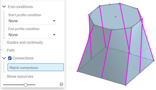
- Select an alternate set of vertices/edges to use:
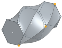
每個連接必須要有兩個選取項目。若要為連接加入第二個選取項目,請按一下「頂點或邊線」方塊 (點選時會變為藍色)。若要加入另一組連接,請先點按「連接」方塊 (點選時也會變為藍色),然後再選取第二對的頂點/邊線。
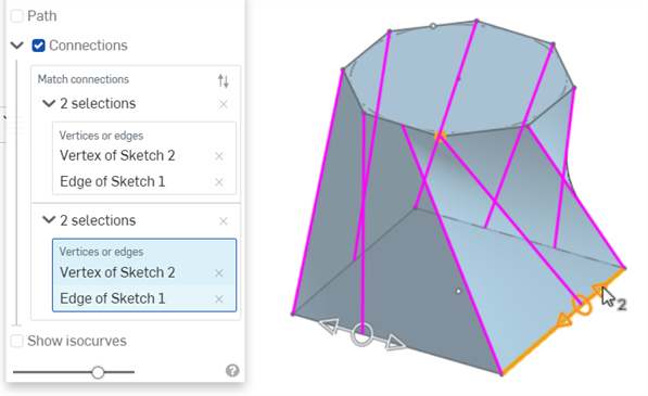
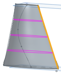
在建立連接之後,您可以使用操控器來拖曳調整所產生的形狀 (同時顯示於上方圖片中)。
- 按一下「連接」。系統會以紫紅色顯示自動連接。只有在沒有「配對連接」項目時才會顯示自動連接。
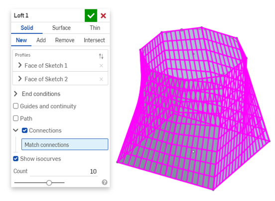
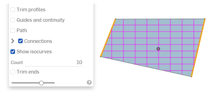
- 選擇性地選取「顯示 isocurves」以在疊層拉伸面上顯示網格的鋪覆。「計數」會決定每個面上的 isocurves 數量。
- 對於「加入」、「移除」或「相交」結果的操作,選擇性地核取「全部合併」,或是選擇一個「合併範圍」來選取要與疊層拉伸零件合併的零件。詳細資訊請參考下方的「合併範圍」。
- 按一下
。
Onshape 會記住選取的項目 (實體、曲面或薄件),在後續的操作中打開對話方塊時即會有之前選取的項目。
![關閉](../Skins/Default/Stylesheets/Images/transparent.gif)
- 按一下
。
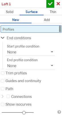
- 選擇曲面建立類型。
- 指定「結果」操作類型:
- New - Create a new surface.
- Add - Add to an existing surface.
-
選擇輪廓 (一個區域、面、邊線或點), 然後 (選用) 選擇橫截面 (依疊層拉伸方向的順序) ,最後選擇結束輪廓 (區域、面、邊線或點)。
若要以單一連續來選擇一組相切連接的曲線,在對話方塊中按一下所要選取項目旁的箭頭以展開選取項目的欄位 (藍色的欄位表示是使用中的)。選擇多條曲線來建立多重的選擇。
- To refine the shape further, select a Start and/or End profile condition to define the derivative constraints on the start and end profiles:
- Normal to profile - Causes the loft to touch the profile with tangents parallel to the profile's normal.
- Tangent to profile - Causes the loft to touch the profile with tangents on the profile plane.
- Match tangent - Causes the loft to match the tangents of model faces adjacent to the profile face (if available). Optionally, when selected, the Adjacent faces field is enabled. Pick any face in which underlying geometry is coincident with at least one profile part's curve (the face and edge do not need to intersect or be part of the same part).
- Match curvature - Causes the loft to match the curvature of model faces adjacent to the profile face (if available). Optionally, when selected, the Adjacent faces field is enabled. Pick any face in which underlying geometry is coincident with at least one profile part's curve (the face and edge do not need to intersect or be part of the same part).
- Normal direction - Causes the loft profile to be normal to a selected direction, for example, a line or mate connector. Optionally, enter a positive or negative Magnitude value to adjust the surface shape according to one profile or another.
- Tangent direction - Causes the loft profile to be tangent to a selected direction, for example, a line or mate connector. Optionally, enter a positive or negative Magnitude value to adjust the surface shape according to one profile or another.
-
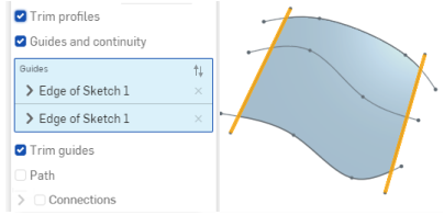
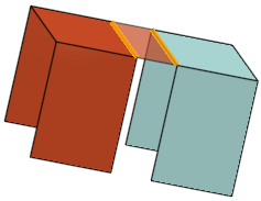
修剪輪廓 - 將疊層拉伸操作沿著輪廓修剪至輪廓與導引的相交處。下方的圖片顯示選取了導引的經修剪輪廓:
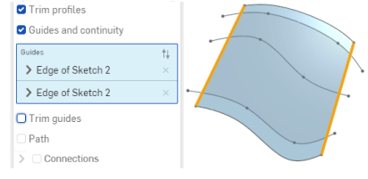
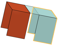
下圖的圖片顯示同時選取了 [修剪導引] 與 [修剪輪廓],會將疊層拉伸同時沿著導引與輪廓修剪:
- 選擇性地使用一或多條導引曲線以供疊層拉伸進行;導引曲線必須接觸輪廓的外側而非中心。
- Check the Guides and continuity box.
- 選擇要用來做為導引的一或多條曲線。
- To select tangentially connected curves as a single guide, click the down arrow next to the selected guide to open the field for more selections.
- Make additional selections:
1 and 2: Each of these is a single guide selection (“Edge of Loft 1” and “Edge of Sketch 3”).
3: Click the arrow next to the guide name to expand the field.
4: The blue highlighting indicates that field is active. At this point, you can select more adjacent curves to create a composite guide selection.
(Optional) For further definition, use the Continuity condition on the guide. Continuity can be:
- Normal to guide - Causes the loft to touch the guide with tangents parallel to the guide's normal.
- Tangent to guide - Causes the loft to touch the guide with tangents on the guide' s plane.
- Match tangent - Causes the loft to match the face tangent of the guides adjacent to the profile.
- Match curvature - Causes the curvature of the loft faces to match the curvature of the guides adjacent to the profile.
Make sure that your sketch is consistent with what you are selecting, if the sketch is inconsistent with Match tangent and it is selected, the loft will fail. The same is true for Match curvature.
- Make additional selections:
-
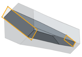
當選取了導引和連續性時,可使用修剪導引。這些選項讓您可控制導引對疊層拉伸操作的影響,特別是在將疊層拉伸操作修剪至導引的邊界時。
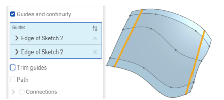
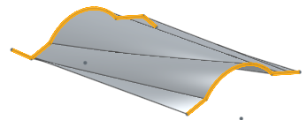
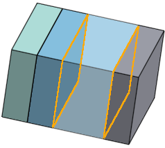
下圖的圖片並無選取任何 [修剪],疊層拉伸延伸至輪廓的長度以及導引的長度 (於下圖中強調顯示):
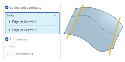
下方的圖片選取了 [修剪導引],會將疊層拉伸沿著導引修剪至輪廓與導引的相交處:
- 要建立等同中心線,請選擇一條路徑路徑來讓疊層拉伸進行 (並產生沿著路徑的居間剖面來讓疊層拉伸參考)。
- 按一下「路徑」旁的方塊。
- 選擇邊線、曲線與草圖來做為疊層拉伸的路徑 (中心線導引)。
- 指定沿路徑要使用的剖面數量 (居間剖面數)。使用的剖面數量越多,路徑會更精準地進行。
For example: Straight line selected as the path, section count = 3
選取樣條做為路徑,剖面數量 = 10
- 選擇性使用,選擇連接來對所產生曲面的扭轉有更多的控制。如果有導引線,會將其用於對齊上。如果沒有,則 Onshape 會約計現有頂點間的鄰近性。最佳的方式是在每個輪廓上至少有兩個頂點,並使用相配的頂點來控制扭轉:
- 按一下「連接」。系統會以紫紅色顯示自動連接。只有在沒有「配對連接」項目時才會顯示自動連接。
- 選擇一組頂點 (在每個區域/面/邊線/點上選擇一個頂點),或一個頂點一條曲線:
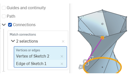
使用操控器來變更頂點/邊線的對齊:
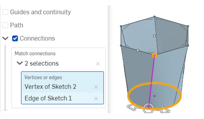
- 選擇性地選取「顯示 isocurves」以在疊層拉伸曲面上顯示網格的鋪覆。「計數」會決定 isocurves 數量。
- 對於「加入」結果的操作,選擇性地核取「全部合併」,或是選擇一個「合併範圍」來選取要與新 (新增) 零件合併的零件。詳細資訊請參考下方的「合併範圍」。
- 按一下
。
Onshape 會記住選取的項目 (實體、曲面或薄件),在後續的操作中打開對話方塊時即會有之前選取的項目。
![關閉](../Skins/Default/Stylesheets/Images/transparent.gif)
- 按一下
。
- 選擇薄件建立類型。
-
指定「結果」操作類型:
- New - Create a new solid.
- 加入 - 加入至現有的實體。
- 移除 - 從現有的實體中去除。
- 相交 - 僅保留兩個 (或多個) 實體的相交。
-
Select Profiles (a region, face, edge, or point) and then optional cross-sections (in order of the loft direction) and finally the end (region, face, edge, or point).
Select more profiles to create a composite selection.
-
執行下列操作之一:
-
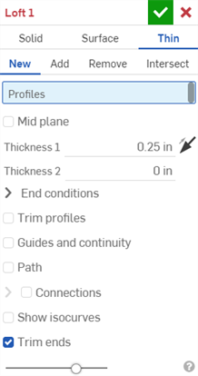
To use a symmetric thickness, check the Mid plane option and then enter the Thickness value. The loft will extend equally in both directions from the midplane.
-
To specify individual wall thicknesses, uncheck the Mid plane option. Then, enter the Thickness 1 wall value and Thickness 2 wall value. Click the Flip wall arrow to flip Thickness 1 with Thickness 2.
-
- To refine the shape further, select a Start and/or End profile condition to define the derivative constraints on the start and end profiles:
- Normal to profile - Causes the loft to touch the profile with tangents parallel to the profile's normal
- Tangent to profile - Causes the loft to touch the profile tangent to the profile plane.
- Match tangent - Causes the loft to match the tangents of model faces adjacent to the profile face (if available). Optionally, when selected, the Adjacent faces field is enabled. Pick any face in which underlying geometry is coincident with at least one profile part's curve (the face and edge do not need to intersect or be part of the same part).
- Match curvature - Causes the loft to match the curvature of model faces adjacent to the profile face (if available). Optionally, when selected, the Adjacent faces field is enabled. Pick any face in which underlying geometry is coincident with at least one profile part's curve (the face and edge do not need to intersect or be part of the same part).
- Normal direction - Causes the loft profile to be normal to a selected direction, for example, a line or mate connector. Optionally, enter a positive or negative Magnitude value to adjust the surface shape according to one profile or another.
- Tangent direction - Causes the loft profile to be tangent to a selected direction, for example, a line or mate connector. Optionally, enter a positive or negative Magnitude value to adjust the surface shape according to one profile or another.
- Normal to profile - Causes the loft to touch the profile with tangents parallel to the profile's normal
-
修剪輪廓 - 將疊層拉伸操作沿著輪廓修剪至輪廓與導引的相交處。下方的圖片顯示選取了導引的經修剪輪廓:
下圖的圖片顯示同時選取了 [修剪導引] 與 [修剪輪廓],會將疊層拉伸同時沿著導引與輪廓修剪:
- 選擇性地使用一或多條導引曲線以供疊層拉伸進行;導引曲線必須接觸輪廓的外側而非中心。
- Check the Guides and continuity box.
- 選擇要用來做為導引的一或多條曲線。
- (Optional) To select tangentially connected curves as a single guide, click the down arrow next to the selected guide to open the field for more selections.
- Make additional selections:
1 and 2: Each of these is a single guide selection (“Edge of Loft 1” and “Edge of Sketch 3”).
3:按一下導引名稱旁的箭頭來展開欄位。
4:藍色的強調顯示表示欄位是使用中的。在這個時候,您可以選擇更多相鄰的曲線來建立多重的導引選取項目。
- (Optional) For further definition, use the Continuity condition on the guide. Continuity can be:
- Normal to guide - Causes the loft to touch the guide with tangents parallel to the guide's normal.
- Tangent to guide - Causes the loft to touch the guide with tangents on the guide's plane.
- Match tangent - Causes the loft to match the face tangent of the guides adjacent to the profile.
- Match curvature - Causes the curvature of the loft faces to match the curvature of the guides adjacent to the profile.
Make sure that your sketch is consistent with what you are selecting, if the sketch is inconsistent with Match tangent and it is selected, the loft will fail. The same is true for Match curvature.
- Make additional selections:
-
當選取了導引和連續性時,可使用修剪導引。這些選項讓您可控制導引對疊層拉伸操作的影響,特別是在將疊層拉伸操作修剪至導引的邊界時。
下圖的圖片並無選取任何 [修剪],疊層拉伸延伸至輪廓的長度以及導引的長度 (於下圖中強調顯示):
下方的圖片選取了 [修剪導引],會將疊層拉伸沿著導引修剪至輪廓與導引的相交處:
- 要建立等同中心線,請選擇一條路徑路徑來讓疊層拉伸進行 (並產生沿著路徑的居間剖面來讓疊層拉伸參考)。
- Click the Path box.
- 選擇邊線、曲線與草圖來做為疊層拉伸的路徑 (中心線導引)。
- 指定沿路徑要使用的剖面數量 (居間剖面數)。使用的剖面數量越多,路徑會更精準地進行。
For example: Straight line selected as the path, section count = 3
選取樣條做為路徑,剖面數量 = 10
- Optionally, select Connections to have more control on the twist of the resulting surface. If there are guides, those are used for alignment, if there are no guides then Onshape estimates the proximity within the existing vertices. It is best to have at least two vertices on each profile and use the matching vertices to control twist. The automatic connections are displayed in magenta. Automatic connections are only visible if there are no Match connection entries.
- 選擇一組頂點 (在每個區域/面/邊線/點上選擇一個頂點),或一個頂點一條曲線:
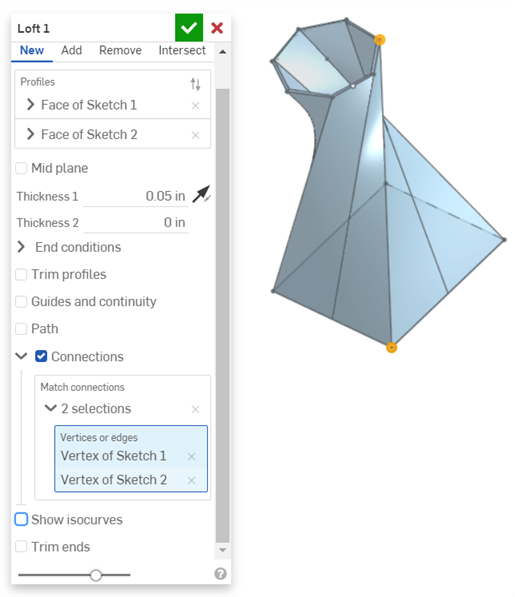
使用操控器來變更頂點/邊線的對齊:
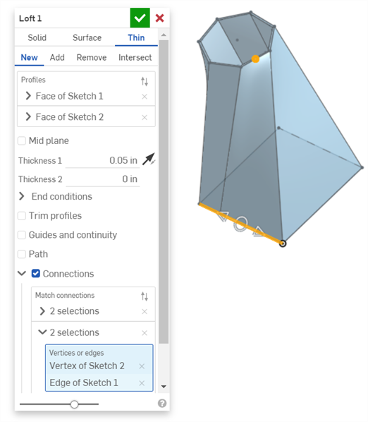
- 選擇一組頂點 (在每個區域/面/邊線/點上選擇一個頂點),或一個頂點一條曲線:
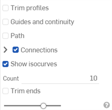
- Optionally, select Show isocurves to show a mesh overlay on the loft surface. The Count determines the number of isocurves.
-
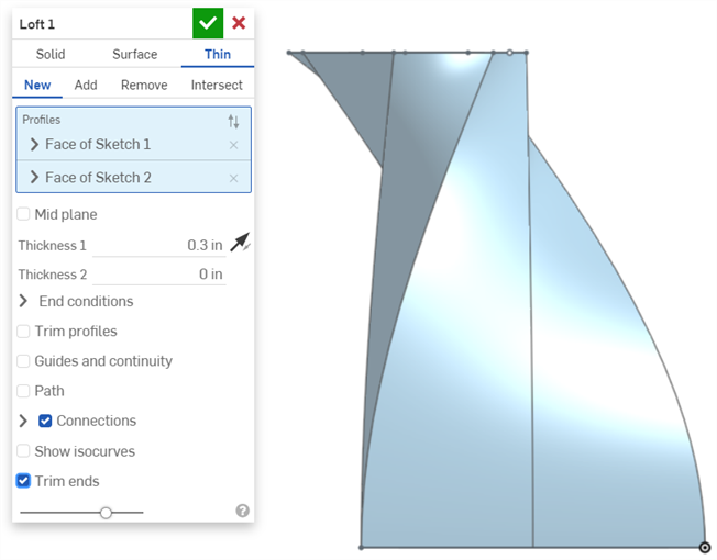
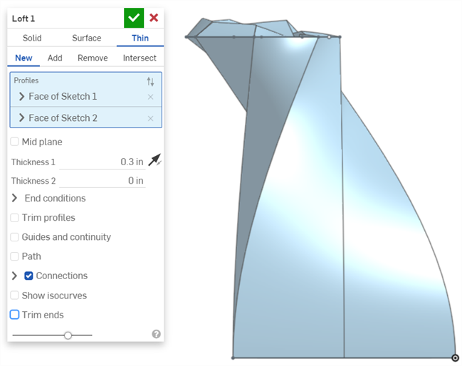
Check the Trim ends option to start and terminate the loft at the profiles.
Uncheck it to create end faces tangent to the profiles.
- For the Add result operation, optionally check Merge with all, or select a Merge scope to select parts with which to merge the new (additional) part.
- 按一下
。
Onshape 會記住選取的項目 (實體、曲面或薄件),在後續的操作中打開對話方塊時即會有之前選取的項目。
![關閉](../Skins/Default/Stylesheets/Images/transparent.gif)
曲面 / 加入 / 導引線 / 配對曲率 - 建立材料並加入至現有的材料中。

![關閉](../Skins/Default/Stylesheets/Images/transparent.gif)
新 - 建立造成新零件或曲面的新材料。
加入 - 建立材料並加入至現有的材料中 (在這個範例中是與所有現有的材料合併;您也可以選擇一個零件來做為合併範圍)。
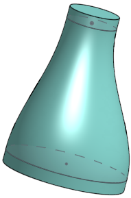
-
當加入材料時,您可以選擇將材料與其幾何接觸或相交的零件合併。
-
如果幾何僅與一個零件接觸或相交,則自動會將該零件加入至合併的範圍中。
- 如果多個零件與幾何接觸或相交,則有模糊的情況產生,您必須選擇要合併的零件 (合併範圍)。
- 一個選擇多個接觸或相交零件的捷徑是核取全部合併來將接觸或相交的零件加入至合併範圍中。
- 請注意,如果布林運算是設定為「加入」、「移除」、或「相交」,且在合併範圍內沒有設定任何項目,則特徵會有錯誤。對於「新」的選項,因為不會對結果進行布林運算,所以不提供合併範圍。
![關閉](../Skins/Default/Stylesheets/Images/transparent.gif)
選擇沿著疊層拉伸輪廓的草圖來從現有材料中移除材料;不適用於曲面中。
![關閉](../Skins/Default/Stylesheets/Images/transparent.gif)
僅在所選幾何重疊處保留材料;如果需要,請選擇 [全部合併] 來完成操作;不適用於曲面中。
![關閉](../Skins/Default/Stylesheets/Images/transparent.gif)
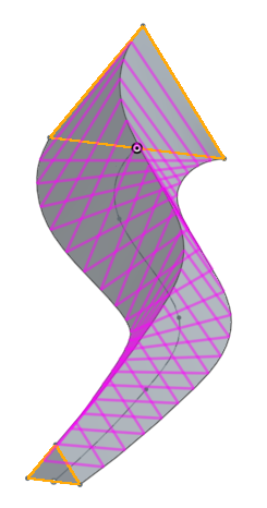
選擇一條路徑來做為疊層拉伸的同等中心線 (導引線),並藉以控制疊層拉伸的整體形狀。這條導引線不一定要在中心。指定沿著路徑的居間剖面數量來微調延路徑所產生疊層拉伸的形狀。
未使用路徑的疊層拉伸:
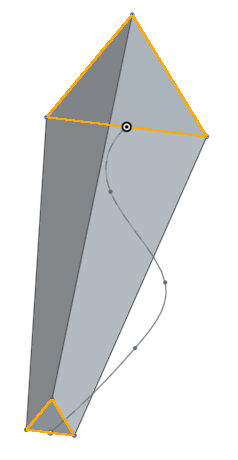
使用路徑與 2 個居間剖面的疊層拉伸:
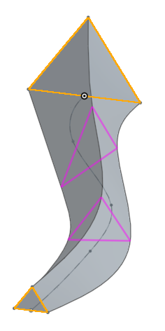
使用路徑與 20 個居間剖面的疊層拉伸:
![關閉](../Skins/Default/Stylesheets/Images/transparent.gif)
可在零件與曲面上使用 [合併範圍],讓您選擇要與新建立零件或曲面合併的特定零件或曲面。根據預設已選取了 [全部合併]。您可以取消核取該方塊來存取 [合併範圍] 的欄位,然後選擇要合併的零件或曲面。曲面必須與曲面合併,零件則須與零件合併。
合併範圍:全部合併
將擠出與其相交的所有零件合併
合併範圍:特定零件
選擇要合併的特定零件
![關閉](../Skins/Default/Stylesheets/Images/transparent.gif)
選擇一組頂點 和/或邊線 (每個輪廓上一個)。
![關閉](../Skins/Default/Stylesheets/Images/transparent.gif)
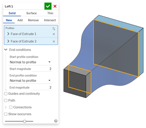
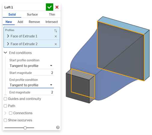
選擇起始輪廓形態與終止輪廓形態 (在起始與終止輪廓上有衍生的限制條件)。對於每個終止形態 (起始輪廓與終止輪廓),您可以指定一個量值。
垂直於輪廓 - 使疊層拉伸的切線的切線平行於輪廓法線建立接觸輪廓的疊層拉伸
與輪廓相切 - 使疊層拉伸的切線在輪廓平面上建立接觸輪廓的疊層拉伸
Match tangent - Causes the loft to match the tangents of model faces adjacent to the profile face (if available).
選擇性使用,選取時系統會啟用「相鄰面」欄位。選取任何一個面,其基礎幾何須與至少一個輪廓零件的曲線重合 (面與邊線不需相交或是同一零件的一部分)。
Match curvature - Causes the loft to match the curvature of model faces adjacent to the profile face (if available).
選擇性使用,選取時系統會啟用「相鄰面」欄位。選取任何一個面,其基礎幾何須與至少一個輪廓零件的曲線重合 (面與邊線不需相交或是同一零件的一部分)。
Normal direction - Causes the loft profile to be normal to a selected direction, for example, a line or mate connector. Optionally, enter a positive or negative Magnitude value to adjust the surface shape according to one profile or another.
Tangent direction - Causes the loft profile to be tangent to a selected direction, for example, a line or mate connector. Optionally, enter a positive or negative Magnitude value to adjust the surface shape according to one profile or another.
![關閉](../Skins/Default/Stylesheets/Images/transparent.gif)
- 要獲得最佳的結果,所有的輪廓應該有相同的曲線線段數量。
- 頂點的選擇必須從每個輪廓中選擇一個頂點。
- 在疊層拉伸操作中使用的輪廓 (區域) 與導引在輸入欄位中必須是單一的輸入。
- 當操作多條邊線的導引曲線時,請確定一個草圖定義了導引;請從特徵清單中選擇該草圖。
- 請確定從疊層拉伸的開始到結束選擇了正確的輪廓 (區域、面、邊線或點) 順序。
- 導引曲線需要是平滑的 (多邊線曲線必須是相切的),且必須接觸輪廓 (請使用重合或貫穿的限制條件)。
- 在建立疊層拉伸之後,於編輯的過程中使用 「成品」按鈕來顯示結果與微調操作。
- 目前不支援輪廓中的嵌套式迴圈。
- 要選擇多條相切連接的曲線做為單一導引,請從「特徵」清單中以完整草圖的方式選擇這些曲線,或在「零件」清單中以曲線的方式選擇。
![關閉](../Skins/Default/Stylesheets/Images/transparent.gif)
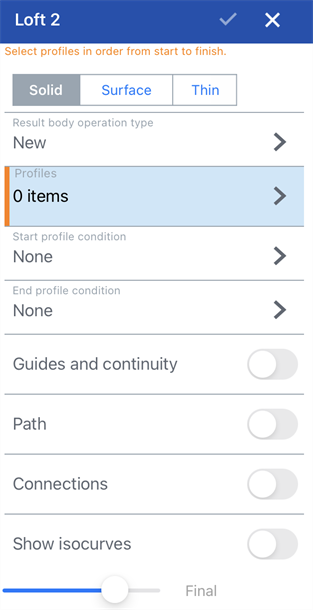
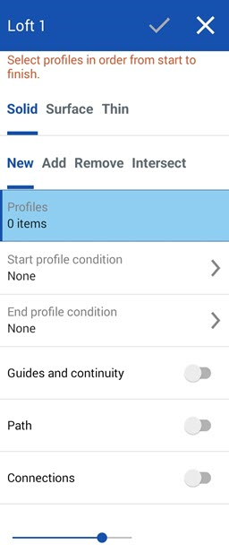
- 輕觸疊層拉伸工具。
Loft dialog for iOS (left) and Android (right)
- Select Creation type:
- Solid - Create parts or modify existing parts.
- Surface - Create a surface along a sketch curve.
- Thin - Creates a thin loft.
- 選擇一個「結果本體操作類型」:
- 新 - 建立造成新零件的新材料。
- 加入 - 建立新材料並加入至現有的材料中。
- 移除 - 將材料從零件中移除。
- 相交 - 僅留下相交存在處的材料。
- Profiles - Select Profiles to loft:
請先選擇開始的輪廓 (一個區域、面、邊線或點), 然後 (選用) 選擇橫截面 (依疊層拉伸方向的順序) 來幫助限制疊層拉伸的形狀,最後選擇結束輪廓 (區域、面、邊線或點)。
- Start and End profile condition - Select a Start profile condition and End profile condition (derivative constraints on the start and end profiles to help define the loft). For each condition, you are able to specify a magnitude (use the number pad to change these values):
- None
- Normal to profile - Causes the loft to touch the profile with tangents parallel to the profile's normal
- Tangent to profile - Causes the loft to touch the profile with tangents on the profile plane
- Match tangent - Causes the loft to match the tangents of model faces adjacent to the profile face (if available). Optionally, when selected, the Adjacent faces field is enabled. Pick any face in which underlying geometry is coincident with at least one profile part's curve (the face and edge do not need to intersect or be part of the same part).
- Match curvature - Causes the loft to match the curvature of model faces adjacent to the profile face (if available). Optionally, when selected, the Adjacent faces field is enabled. Pick any face in which underlying geometry is coincident with at least one profile part's curve (the face and edge do not need to intersect or be part of the same part).
- Normal direction - Causes the loft profile to be normal to a selected direction, for example, a line or mate connector.
- Tangent direction - Causes the loft profile to be tangent to a selected direction, for example, a line or mate connector.
- Guides and continuity - Select the guide lines (guide lines must be touching the outsides of the profiles, not the centers). To select a set of connected curves as a single chain, select them from the Feature list as a complete sketch.
- Path - Select a path (centerline guide) for the loft to follow (and create intermediate sections along the path for the loft to reference).
- 輕觸來切換路徑。
- 選擇邊線、曲線與草圖來做為疊層拉伸的路徑 (中心線導引)。
- 指定沿路徑要使用的剖面數量 (居間剖面數)。使用的剖面數量越多,路徑會更精準地進行。
- Connections - Select optional vertices to match (to define corresponding locations on each profile):
- 輕觸來切換連接。
- 選擇一組頂點 (在每個區域/面/邊線/點上選擇一個頂點或邊線)。
- Show isocurves - Optionally, select this option to show a mesh overlay on the loft surface. The Count determines the number of isocurves.
- Click the checkmark to accept the Loft.
For more information on the Loft feature and examples, see the Loft: Desktop section above.