![]()
![]()
![]()
![]()
根據預設,當您從零件、曲線、曲面或次組合件中建立工程圖時,可以不於其中放置任何視圖,或使用 4 個標準視角:上視、前視、右視、與等角視。通常而言,視角的投影是根據所選的標準:ISO 標準是第一角投影法,ANSI 標準則是第三角投影法,您也可以使用自訂的範本並選擇投影法,或是在建立工程圖之後變更投影法。
例如,標準的 ANSI 工程圖會像是這樣:
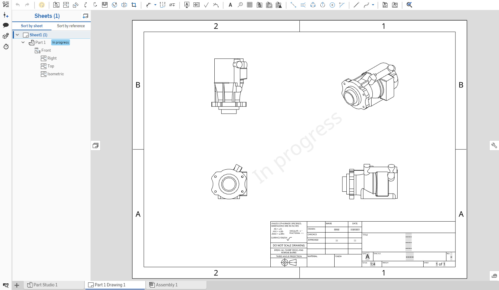
工程圖中零件、曲線或曲面的所有視角是來自相同版本的零件。當建立視圖 (工程圖 - 投影、輔助、剖面) 時,會使用與所有現存視圖所使用的相同零件版本。
會將視圖放置在圖頁上,並可以與其他視圖有關係。
此表格說明視圖的類型以及可以從其中產生的視圖:
| 投影視圖 | |
| 可以從這些項目建立: | 無法從這些項目建立: |
|
基本視圖 投影視圖 剖面視圖 轉正剖視圖 輔助視圖 有區域深度剖視圖的視圖 「投影視圖」會保留其來源視圖的設定。從區域深度剖視圖而來的投影視圖也會被切開。 展開圖樣視圖 |
細部放大圖 |
| 輔助視圖 | |
| 可以從這些項目建立: | 無法從這些項目建立: |
|
裁剪視圖 基本視圖中的線性邊線 正射投影視圖中的線性邊線 輔助視圖中的線性邊線 等角視圖中的線性邊線 剖面視圖中的線性邊線 轉正剖視圖中的線性邊線 在「對正」輔助視圖中的草圖線 在「對正」輔助視圖中的中心線 展開圖樣視圖 |
細部放大圖 斷開視圖 |
| 剖面圖 | |
| 可以從這些項目建立: | 無法從這些項目建立: |
|
輔助視圖 斷開視圖 裁剪視圖 細部放大圖 基本視圖中的位置 等角視圖中的位置 正射投影視圖中的位置 剖面視圖與轉正剖視圖 有區域深度剖視圖的視圖 展開圖樣視圖 |
與圓柱面相切的割面線 |
| 轉正剖視圖 | |
| 可以從這些項目建立: | 無法從這些項目建立: |
|
輔助視圖 裁剪視圖 細部放大圖 基本視圖中的位置 等角視圖中的位置 正射投影視圖中的位置 剖面視圖與轉正剖視圖 有區域深度剖視圖的視圖 展開圖樣視圖 |
與圓柱面相切的割面線 |
| 區域深度剖視圖 | |
| 可以從這些項目建立: | 無法從這些項目建立: |
|
投影視圖 輔助視圖 斷開視圖 區域深度剖視圖 裁剪視圖 有另一個區域深度剖視的視圖 |
剖面視圖 細部放大圖 轉正剖視圖 |
| 細部放大圖 | |
| 可以從這些項目建立: | 無法從這些項目建立: |
|
裁剪視圖 細部放大圖 基本視圖中的位置 正射投影視圖中的位置 等角視圖中的位置 輔助視圖中的位置 剖面視圖中的位置 轉正剖視圖中的位置 展開圖樣視圖 |
|
| 斷開視圖 | |
| 可以從這些項目建立: | 無法從這些項目建立: |
|
基本視圖 投影視圖 輔助視圖 剖面視圖 轉正剖視圖 等角視圖 展開圖樣視圖 |
細部放大圖 |
| 裁剪視圖 | |
| 可以從這些項目建立: | 無法從這些項目建立: |
|
投影視圖 輔助視圖 剖面視圖 轉正剖視圖 有區域深度剖視圖的視圖 |
細部放大圖 斷開視圖 展開圖樣視圖 |
| 展開圖樣視圖 | |
| 可以從這些項目建立: | 無法從這些項目建立: |
|
「插入視圖」對話方塊 |
任何視圖 |
將一個模型 (零件、曲面、組合件、草圖、曲線、複合零件或展開鈑金圖樣) 的視角放置在使用中圖頁上;使用對話方塊來選擇想要的零件、草圖或展開的鈑金型式,包括版本與方位。根據預設,標籤與比例是關閉的。若要查看比例,請連按兩下視圖:「視圖屬性」對話方塊會在工程圖左上方開啟。
- 按一下工具列中的「插入視圖」:
- 按一下對話方塊中的
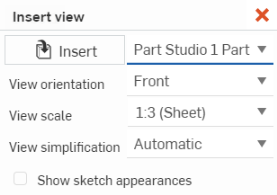
 「插入」按鈕 (下方左圖中所示) 來開啟「選擇零件或組合件」對話方塊 (下方右圖所示)。在目前 (或其他) 文件中搜尋 Part Studio 與組合件來找出零件、曲面、組合件、曲線、或草圖 (或其版本):
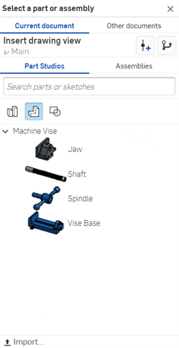
- 選擇來從目前工作區 (在這個文件的 Part Studio 或組合件) 中插入:
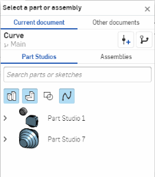
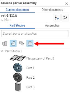
根據預設選取的篩選器是零件,但您也可以搜尋整個 Part Studio、組合件、曲面、草圖、曲線、複合零件與鈑金展開圖樣。僅在所選的 Part Studio 或組合件中包含這些類型的圖元時,這些篩選器的圖示才會出現:
- 或是按一下其他文件來使用慣用的篩選器搜尋,然後從一不同文件的版本中選擇:
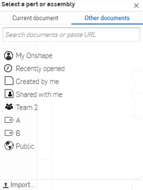
- 在選擇了文件之後,如果文件有版本,按一下
 來開啟版本圖表,然後選擇要從中選取零件或組合件的版本或工作區:
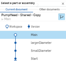
您也可以選擇僅檢視已發行的項目
 ,然後建立一個版本。
- 選擇來從目前工作區 (在這個文件的 Part Studio 或組合件) 中插入:
- 在選取 Part Studio 或組合件之後,使用「插入視圖」對話方塊來選擇一個視圖:

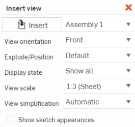
左邊的螢幕擷取畫面顯示 Part Studio 中的「插入視圖」對話方塊;右邊的螢幕擷取畫面顯示在組合件中的對話方塊
對於 Part Studio 與組合件:
選擇「視角方位」:上視、左視、右視、前視 (預設)、後視、下視或等角視。如果有的話,您也可以選擇現有的命名視角 (有或沒有剖切平面)。
選擇「視圖比例」下拉清單來為視圖選擇一個特定的比例。
選擇「視圖簡化」:「無」、 「絕對」、「與 studio 比例」、「與零件比例」、或「自動」(預設)。設定隱藏閾值之下的特徵藉以簡化工程圖中顯示的幾何。這個設定僅會影響新插入的視圖。詳細資訊請參考插入視圖預設。
選擇性地選取「顯示草圖外觀」旁的核取方塊以顯示來自您所插入 Part Studio 或組合件中的外觀。

對於組合件 (如果有的話):
- 一旦您選擇了想要的圖元,在工程圖上按一下來放置視圖。當您放置視圖時會出現預覽。

如果在第一次建立工程圖分頁時,命名視角、爆炸視圖/命名位置和/或顯示狀態是啟用的,則系統會先將該視圖、位置和/或狀態填入「插入視圖」對話方塊中。
快速鍵:p
從一個現有視圖投影來建立新視圖。根據預設,標籤與比例是關閉的。要查看比例,請連按兩下視圖:視圖屬性對話方塊在工程圖左上方開啟。根據預設,在建立工程圖並放置第一個視圖之後,投影視圖工具是啟用的。即使在您使用了投影視圖工具之後,工具仍是啟用的,一直要到您按一下圖示才會關閉。
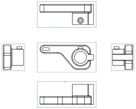
- 按一下來選擇一個現有的視圖。
- 將游標從原始視圖拖曳至不同的方向來檢視可能的投影視圖。
- 按一下來放置新的視圖,或是 Shift+按一下來放置有來自父視圖剖切的新視圖。
- 您也可以在視圖上連按兩下來開啟視圖屬性對話方塊。
建立一個輔助視圖;從父視圖的所選邊線 (通常是從斜邊) 摺疊 90 度的正交投影視圖。或者是您可以建立用於定向輔助視圖的草圖直線或中心線。
-
按一下
 。
。 - 選擇性地提供視圖的標籤
- 選擇一個輔助視圖類型:
- 按一下垂直來建立垂直於線性邊線的輔助視圖。
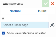
- 按一下對正來建立以草圖直線或中心線定向的輔助視圖。
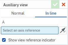
- 按一下垂直來建立垂直於線性邊線的輔助視圖。
- 選擇要定向輔助視圖的邊線或直線。系統會將邊線或直線加入至對話方塊中選擇項目的欄位內。
- 選擇性地按一下「反轉」圖示
 來反轉「輔助視圖」。
 - 根據預設,視圖參考指標是顯示的。取消核取「顯示視圖參考指標」即可隱藏。
- 拖曳游標到輔助視圖的位置,然後按一下來放置視圖。視圖就定位,對話方塊隨即關閉。
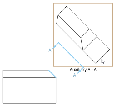
- 根據預設,比例是關閉的。若要查看比例,連按兩下視圖來開啟視圖屬性對話方塊,然後核取底部的「比例」標籤。
比例的輸入可是 N:N 或 N/N 格式。對於使用者輸入的值,第二位數或分母永遠是設定為 1,您可以連按兩下「比例」標籤來編輯。根據預設,會永遠將輔助視圖的比例設定為與父視圖相同 (使用與父視圖相同的比例)。
會自動提供標籤 (您也可以變更),預設是從 A 到 Y,其中略過 I、 O、Q、S、X 與 Z。
選擇一個輔助視圖也會在其父視圖中強調顯示邊線。
按一下來選擇視圖參考指標,並使用在箭號轉折處的抓取點來拖曳直線以縮短或拉長直線。

使用中間抓取點來將視圖參考指標在所選邊線與輔助視圖中間移動。
選擇並在視圖參考指標上按右鍵,可開啟有下列選項的環境選單:
-
編輯輔助視圖 - 開啟「輔助視圖」對話方塊。
-
反轉方向 - 反轉輔助視圖。
-
清除選取項目 - 清除所有圖頁的選擇項目。
-
縮放至適當比例 - 縮放圖頁以配合視圖。
-
刪除 - 刪除「輔助視圖」。
藉由放置切割平面線並指定方向與標籤來建立現有視圖 (包括剖面視圖) 的剖面視圖、轉折的剖面視圖、或部分的剖面視圖。根據預設,標籤是開啟但比例是關閉的。若要查看比例,請連按兩下視圖:「視圖屬性」對話方塊會在工程圖左上方開啟。
- 按一下
 。
。 - 在對話方塊中選擇垂直、水平或角度:
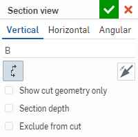
- 選擇性地提供視圖的標籤 (在上方影像中的範例使用 B)。
會自動提供標籤 (您也可以變更),預設是從 A 到 Y,其中略過 I、 O、Q、S、X 與 Z。
- 從下列選項中選擇:
- 僅顯示切除幾何 - 只會顯示切除幾何。
- 切割角度 (僅可是角度) - 輸入精確的角度數值。您也可以使用「相反方向」圖示
 來將角度方向從一邊反轉至另一邊。
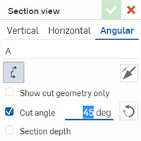
- 剖切深度 - 控制剖切的深度,可以是:
- 成形至圖元 - 使用另一個圖元來設定深度 (然後在工程圖中選擇圖元):
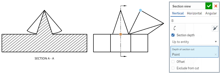
- 給定深度 - 指定深度的量測值:
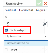
- 成形至圖元 - 使用另一個圖元來設定深度 (然後在工程圖中選擇圖元):
從切割中排除 (僅適用於組合件視圖) - 選擇不要包括在切割中的零件:
放置剖面切割線。
核取對話方塊中的「從切割中排除」。
按一下要在工程圖中排除的任何其他零件。
- 將游標移動至要建立視圖的零件上,暫留來檢視抓取點:
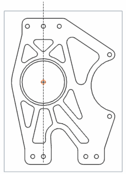
- When the dotted section cutting line is in the desired place, or the snap point is visible, click once to place the line. For angular section views, click a second snap point to set the angle.
- 如果需要,可選取多個抓取點來建立轉折的剖面視圖 (角度的轉折視圖最多可有 4 個點):
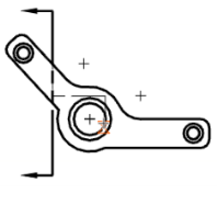
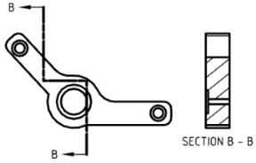
- 將新的剖面視圖從割面線拖曳出來,然後再按一下來放置視圖:
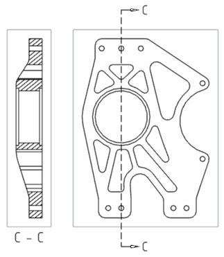
垂直剖面視圖 (上圖)
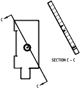
角度剖面視圖 (上圖)
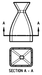
水平剖面視圖 (上圖)
請注意,在按一下放置剖面視圖之前,將剖面視圖拖曳到不同邊會反轉剖面邊:
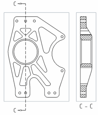
按一下來選擇剖面線,並使用在箭號轉折處的抓取點來拖曳直線以縮短或拉長直線:
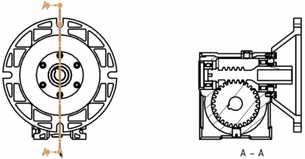
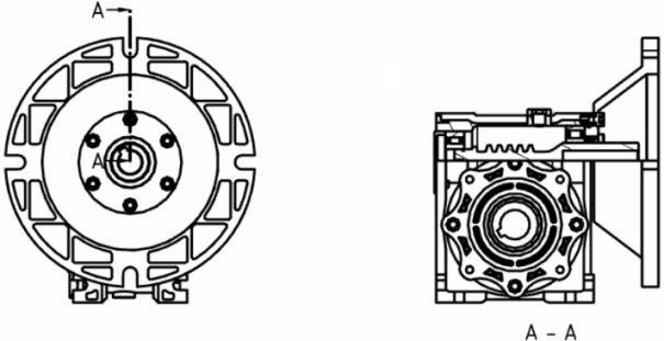
調整零件內部的剖面線長度來建立部分的剖面視圖。
- 連按兩下視圖來開啟「視圖屬性」對話方塊。
選擇一個剖面視圖會在其父視圖中強調顯示切割線。
比例的輸入可是 N:N 或 N/N 格式。對於使用者輸入的值,第二位數或分母永遠是設定為 1,可以連按兩下「比例」標籤來編輯。根據預設,會永遠將剖面視圖的比例設定為與父視圖相同 (使用與父視圖相同的比例)。
一旦放置之後,可以按一下一個抓取點並拖曳到工程視圖中的另一個點上來調整轉折的剖面視圖。轉折的剖面視圖會相對應調整。
有兩種方式可以編輯剖面線圖樣,可以從視圖環境選單中選擇 [編輯剖面線],或是開啟工程圖的「屬性」對話方塊,然後導覽至「視圖」分頁中進行操作。
您可以使用「剖面視圖」工具來從剖面視圖中建立一個剖面視圖:
- 按一下
 。
。 - 在對話方塊中選擇垂直、水平或角度:
- 選擇性地提供視圖的標籤。
-
如果您要從剖切幾何 (已建立的剖面視圖) 中切除,請選擇 [從剖面切割]:
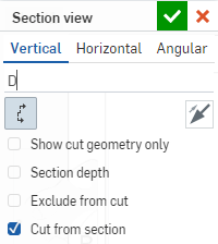
如果您要從基礎幾何中建立視圖,請取消核取 [從剖面切割]。
-
按一下取記號來產生視圖,或按一下 x 來取消操作。
您可以從已套用有區域深度剖視圖的視圖中建立剖面視圖;不過,新剖切形成是從基礎幾何而來,而不是來自區域深度剖切的幾何。
即使剖面是轉折的,您仍可以將斷開視圖加入至水平或垂直的剖面視圖中。同樣地,您可以將水平或垂直的剖面視圖加入至有斷裂的視圖中。變更一個視圖中的斷開位置會在所有相關的視圖中變更位置。
無法從有斷裂的視圖中建立角度剖面視圖,無法在有角度剖面切割線的視圖上建立斷裂。
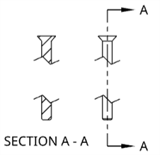
一旦放置了剖面線之後,如果是將其放在抓取點上,可能可將其移動到新的位置上:
- 選擇直線:
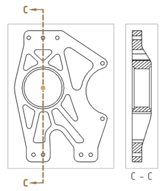
- 按一下並拖曳抓取點到新的位置上:
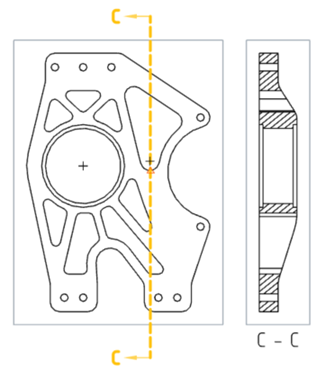
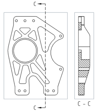
- 按一下來放置剖面線。
- 請注意,相對應的視圖改變:
若要調整剖面線來使得切割短於關聯點 (藍色點):
-
選擇剖面線一端或另一端,然後使用在箭號轉折處的抓取點來將直線拖曳到關聯點之下 (或之上):

-
相對應的剖面視圖會變更:
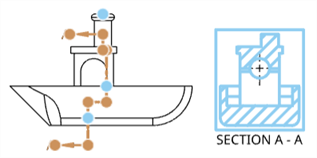
放置剖面線之後反轉剖面線方向:
- 選擇剖面線。
- 按右鍵並選擇反轉方向。
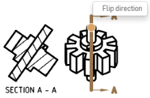
剖面線標籤會換邊,且會對應地重生成視圖。
使用 Onshape 來編輯剖面線:
- 在剖面線 (轉折的剖面線) 上按一下。
- 按右鍵然後從環境選單中選擇 [編輯剖面]。
- 「剖面視圖」對話方塊出現,請於其中編輯您的喜好設定,然後按一下右上角的核取記號來套用您做的編輯。按一下右上角的紅色 x 來取消而不套用編輯。
- 選擇剖面線 (轉折的剖面線)。
- 按右鍵然後從環境選單中選擇 [編輯剖面]。
- 若要新增線段:
- 選擇一個抓取點然後將其拖曳至視圖中想要的位置。
- 將游標在想要位置的新抓取點上暫留,按一下來於該處放置線段。
- 若要移除線段:
- 將游標在您想要移除線段的抓取點上暫留。會在抓取點周圍出現一個橘色的方塊。
- 按一下有橘色方塊的抓取點;抓取點隨即消失。
- 在視圖外的任意處按一下來結束操作。
- 視圖會更新以反映對剖面線做出的變更。
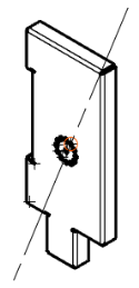
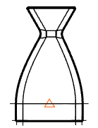
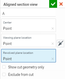
建立一個剖面視圖,其中某些部分被非平行於檢視平面的平面所切割,然後將該部分旋轉對正檢視平面。這種視圖類型常用於有某種程度對稱但不是完全對稱的圓柱零件上。
-
按一下
 。
。
-
指定視圖的標籤。
-
為「中心」欄位點按剖切線的中心。
-
為「檢視平面位置」欄位點按一個點,以從該點投影視圖。
-
為「旋轉平面位置」欄位點按一個點,以從該點旋轉視圖以與其他視圖對齊。
-
選擇性地選取 [僅顯示切除幾何] 來只顯示這個切除幾何的視圖,而不顯示背景幾何:
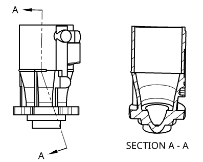
上圖的範例顯示全部的幾何。
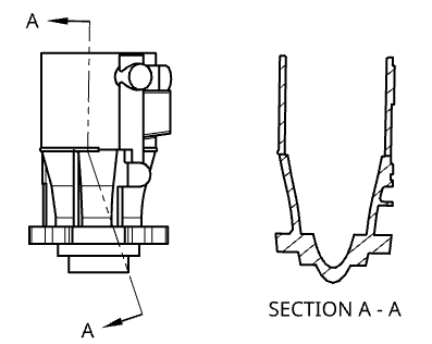
上圖是同樣的範例但僅顯示切除的幾何。
-
選擇性地選取「從切割中排除」(僅適用於組合件視圖) 來選擇不要包括在切割中的零件:
-
放置剖面切割線。
-
核取對話方塊中的「從切割中排除」。
-
按一下要在工程圖中排除的任何其他零件。
-
-
在工程圖上按一下來放置視圖。當您拖曳放置視圖時,從原始視圖的一側移動到另一側會反轉檢視平面的箭號。
若要編輯視圖,請在視圖上按右鍵並選擇 [編輯] 來開啟編輯的對話方塊。如果更新工程圖導致懸置的圖元,則可能需要編輯視圖。在對話方塊中懸置的圖元會以紅色的標示顯示。
當從剖面視圖或轉正剖視圖中切割轉正剖面時,根據預設會選取 [從剖面切割]。
使用「樣條」工具定義一個封閉的輪廓,來在工程視圖中建立切除模型一部分的區域深度剖視圖。
- 按一下
 。
。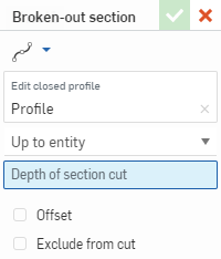
- 使用「樣條」工具來為視圖定義封閉的輪廓。
使用「樣條點」工具來加入點以編輯樣條。
- 選擇一個終止類型,可以是「給定深度」或指定深度,或是「成形至圖元」 (然後選擇在另一視圖上的點或邊線)。
- 選擇性地選取「偏移」來指定從切割偏移的距離。
-
選擇性地選取「從切割中排除」(僅適用於組合件視圖) 來選擇不要包括在切割中的零件:
-
放置剖面切割線。
-
核取對話方塊中的「從切割中排除」。
-
按一下要在工程圖中排除的任何其他零件。
-
- 按一下
 。
。
您也可以在視圖上連按兩下來開啟視圖屬性對話方塊。按右鍵並選擇 [編輯剖面] 來重新開啟對話方塊並編輯視圖的設定項目 (或 [移除剖面] 來從工程圖中刪除區域深度剖視圖)。
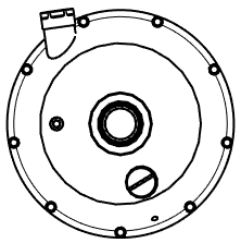
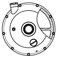
左邊是套用區域深度剖視圖之前的視圖;右邊則是產生的區域深度剖視圖
請注意,深度點 (由上方所述的終止類型所定義) 是與模型相關聯的。因此,如果對模型的修改會導致深度點的變更,則區域深度剖視圖的樣條與深度點會與工程圖一起更新。不過在某些案例中,更新可能會導致錯誤。會以紅色顯示區域深度剖視圖的樣條;如果發生這樣的問題,請重新定義深度點來改正錯誤。
使用細部放大圖來選擇放大現有視圖的一個區域以查看更多細節。
-
按一下
 來開啟細部放大圖對話方塊:
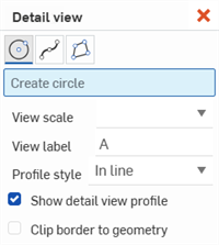
- 選擇圓、矩形、樣條、或多邊形工具來建立封閉的區域。
- 在視圖比例欄位中選擇視圖的比例。
- 如果需要,請在視圖標籤欄位中調整標籤。
-
從輪廓樣式欄位中選擇一個選項:
- 行內 - 標籤出現在來源視圖中。
- 連接 - 使用虛線來將細部放大圖與來源連接 (請注意,選擇這個選項時標籤不會出現)。
- 導線 - 使用線條與箭頭來將標籤與來源連接。
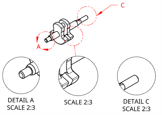
左圖:標籤 A 出現在行中。中圖:標籤 B 是隱藏的,且細部放大圖與來源是以虛線連接的。右圖:標籤 C 是以線條和箭頭來與來源連接。
- By default, the detail view is outlined with a circle, rectangle, spline, or polygon to match the outline on the source view. To remove the outline from the Detail view, deselect the Show detail view profile checkbox.
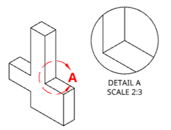
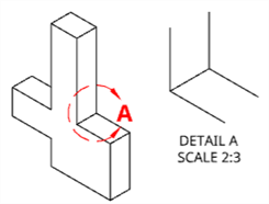
左圖:當選取了「顯示細部放大圖輪廓」選項時,細部放大圖與來源視圖同時有圓的輪廓線。右圖:當未選取「顯示細部放大圖輪廓」選項時,細部放大圖沒有以輪廓線框出。
- 如果您要顯示沒有額外視圖邊框的細部放大圖幾何,按一下將邊框裁剪至幾何選項。
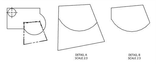
原始的前視圖 (左),停用「將邊框裁剪至幾何」的細部 A (中);啟用「將邊框裁剪至幾何」的細部 B (右)。
-
現在請選擇您要放大的區域。
-
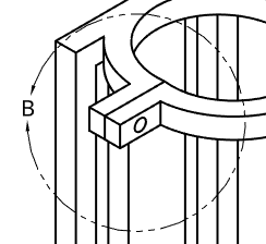
若要使用「圓」工具來建立封閉區域,請在您要放大區域的大概中心處按一下 (在現有視圖上),然後拖曳並再次點按以定義區域的圓周:
-
若要使用「樣條」或「多邊形」工具,按一下來放置第一個點,移動您的滑鼠然後再次點按,重複這些步驟ˊ直到建立了想要的封閉區域。
-
若要選擇現有的封閉區域,請先按下 Esc 鍵,然後按一下該區域。
-
-
拖曳然後再按一下以放置細部放大圖:
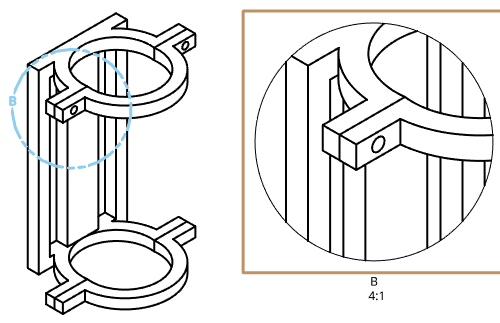
您可以使用視圖屬性對話方塊來編輯細部放大圖的比例與標籤。選擇細部放大圖會在其父視圖中強調顯示細部放大圖圓形。
調整細部放大圖的大小:
- 將游標移動到視圖上暫留來啟用強調顯示:
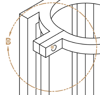
- 選擇箭頭間的抓點
- 向內或向外拖曳來調整視圖的大小。
重新定位細部放大圖:
- 將游標移動到視圖上暫留來啟用強調顯示:

- 選擇視圖圓圈中心的抓點。
- 拖曳至新位置。
重新定位細部放大圖名稱:
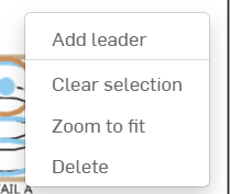
- 在細部放大圖上按右鍵以叫出環境選單。

-
選擇 [加入導線]。
-
拖曳導線與細部放大圖名稱至所需的長度與位置。
使用斷開視圖以修剪掉一部分來縮短現有視圖。
- 按一下
 。
。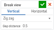
- 指定水平或是垂直的折斷。
- 指定折斷線類型與間隙距離:
- 鋸齒
- 小鋸齒
- 曲線
- 直線
-
在視圖上按一下來放置兩條折斷線 (用以標示出間隙處)
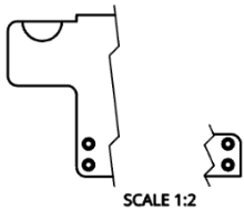
請注意,您可以連按兩下來開啟視圖屬性對話方塊。
若要刪除折斷線,按一下來選擇它並按下 Delete。
即使剖面是轉折的,您仍可以將斷開視圖加入至水平或垂直的剖面視圖中。同樣地,您可以將水平或垂直的剖面視圖加入至有斷裂的視圖中。變更一個視圖中的斷開位置會在所有相關的視圖中變更位置。
無法從有斷裂的視圖中建立角度剖面視圖,無法在有角度剖面切割線的視圖上建立斷裂。

若要裁剪視圖,請在您要保留的區域周圍繪製一個圓、樣條、或多邊形。
- 按一下
 。
。
- 選擇一個草圖形狀,然後在您要保留區域的周圍繪製形狀:
- 圓:按一下來放置圓心,然後再次點按來放置圓周的邊緣。
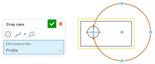
- 樣條:按一下來放置樣條點。連按兩下來結束樣條。
- 若要加入一個樣條點,按一下樣條下拉清單,然後選擇加入樣條點。

- 多邊形:按一下來放置多邊形的角落。連按兩下來結束多邊形。
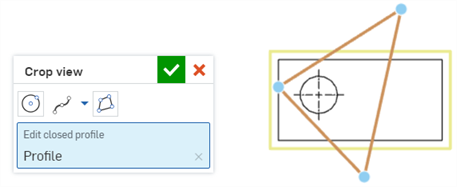
- 圓:按一下來放置圓心,然後再次點按來放置圓周的邊緣。
- 按一下
 。
。

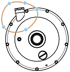
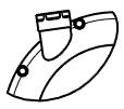
原始視圖 (左圖);樣條定義了裁剪邊界 (中圖);產生的裁剪視圖 (右圖)。
- 在視圖上按右鍵,然後選擇編輯裁剪來重新開啟對話方塊,於其中編輯規格。
- 在視圖上按右鍵,然後選擇移除裁剪來從工程圖中刪除裁剪視圖。
刪除視圖
- 使用上面所提的任何方法來選擇要刪除的視圖。
- 按下 Delete 鍵或按右鍵來啟動環境選單並選擇 [刪除]。
移動視圖
- 選擇視圖。
- 拖曳至想要的位置。
將視圖移至另一圖頁中
您可以使用三個步驟來將任何視圖移動至工程圖中已存在的圖頁上:先使用環境選單中的移至圖頁指令,然後在視圖屬性對話方塊的圖頁下拉清單中選擇一個新的圖頁,最後將視圖拖曳到「圖頁」面板中的另一個圖頁上。
當將視圖移動至另一圖頁中時,所有相關的圖元 (標籤、尺寸等) 會隨其移動。
當移動輔助視圖時,父視圖並不會移動。
當移動父視圖時,輔助視圖並不會移動。
複製視圖
在同一圖頁中將視圖從一個位置複製並貼至另一個位置,從同一工程圖中的一個圖頁複製貼上到另一個圖頁,或是從一工程圖中的圖頁複製貼上到同一工作區中另一工程圖圖頁上。您無法將一個工作區中的視圖複製貼上至另一工作區中。例如,從一個文件到另一個文件。
複製任何視圖:
-
按一下視圖來選擇它。
-
按右鍵然後從環境選單中選擇 [複製] (Ctrl+C)。
-
將游標移動至新的位置,按右鍵然後選擇 [貼上] (Ctrl+V) 來放置複製的視圖。
您也可以按住 Alt 鍵來複製一個視圖,然後選擇並拖曳您要複製的視圖。
選擇一個視圖,按右鍵並選取視圖屬性,或您可以連按兩下一個視圖來開啟視圖屬性對話方塊:

您可以選擇一個顯示狀態 (當提供時),視圖會相對應更新。
當選擇了有不同屬性值的多個視圖時,會如下所示在對話方塊的適當欄位顯示「多個值」:
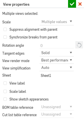
對於「細部放大圖」與「剖面視圖」,有提供額外的「視圖標籤」選項,將於下方詳細說明。
對於由「剖面視圖」建立而來的「投影視圖」,會有操作剖切的額外選項,將說明如下。
- 文件 - 零件或組合件所在處的文件名稱。
- 工作區或版本 - 如果零件或組合件是來自目前的文件中,則會顯示工作區的名稱。如果零件或組合件是在不同的文件中 (當 Part Studios 或組合件被移動至另一文件中時,會自動建立該文件的版本),則會顯示版本的名稱。
- 類型 - 零件或是組合件的工程圖。
- 參考 - 工程圖中零件或組合件的名稱,連結可開啟參考的文件與 Part Studio,或是開啟組合件分頁。
- 視角方位 - 若要從一個視角變更為另一個視角,請從下拉清單中選擇:上視、左視、右視、前視、後視、下視、等角視或命名視角。
- 比例 - 設定工程圖的比例。輸入的格式設定為 N:N 或 N/N。對於使用者輸入的值,第二位數或分母永遠是設定為 1,您可以連按兩下比例標籤來編輯。根據預設,會永遠將投影視圖的比例設定為與父視圖相同 (使用與父視圖相同的比例)。
- 旋轉角度 - 使用此選項來旋轉視圖的角度 (以預設單位)。箭頭會反轉角度的方向。 當建立所有視圖時有 0 度的旋轉角度。您僅能在視圖沒有父視圖 (即視圖不是子視圖),不是父視圖 (沒有子視圖),或與父視圖對齊抑制的情況下改變這個值。
有效的值是介於 0 到 360 度之間。
可以旋轉的視圖也可以沿所選直邊線垂直或水平對齊視圖。
- 切線 - 選擇在視圖中呈現相切線的方式:
- 隱藏 - 從工程圖中移除相切線的顯示。
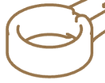
- 實線 - 以實線來顯示相切邊線:

- 影線 - 以斷裂線來顯示相切邊線:
- 隱藏 - 從工程圖中移除相切線的顯示。
- 視圖渲染模式 - 選擇您要使用的渲染模式類型:最佳品質或最佳效能。工程視圖的預設設定是「最佳效能」。如果在某些狀況下邊線無法正確的顯示,可考慮將視圖渲染模式變更為「最佳品質」。渲染模式的設定同時適用於 Onshape 內的工程視圖與匯入工程圖中的視圖。
- 視圖簡化 - 這個功能讓使用者設定隱藏閾值之下的特徵,藉以簡化工程圖中的幾何。
自動 - 預設。根據零件的幾何來找出最佳的視圖簡化設定,並自動使用這些設定來顯示零件或組合件。
絕對 - 輸入工程圖長度單位的數字設定小於這個值的特徵會在視圖中被簡化。如果整個零件小於這個閾值,這些零件都會從視圖中消失。這對於移除在工程圖操作中不需要的額外細節是相當有用的 (例如,為數眾多的小特徵或零組件)。
與 studio 比例 - 輸入 Part Studio 或組合件大小的百分比,小於該值的特徵會在視圖中被簡化。如果整個零件小於這個閾值,這些零件都會從視圖中消失。這對於移除在工程圖操作中不需要的額外細節是相當有用的 (例如,為數眾多的小特徵或零組件)。
與零件比例 - 輸入零件大小的百分比,小於該值的特徵會在視圖中被簡化。這個設定是希望在簡化零件細節的同時將零件保留在視圖中。如果您想要確定所有的零件都出現在視圖中以便建立細節 (例如,放置標註),則此設定是相當有用的。
所有的子視圖會接收其父視圖的視圖簡化設定,但可以稍後獨立變更任何的子視圖,而不會影響在父/子視圖依存關係中的其他視圖設定。
- 圖頁 - 目前顯示圖頁的名稱;使用下拉清單來將視圖移動至另一個圖頁上。
- 名稱 - 視圖名稱的格式是 <遠近透視>-<零件名稱>。變更視圖的名稱並不會修改遠近透視或零件名稱。
在於「圖頁/視圖」清單中選擇了單一視圖的情況下,您可以使用 Shift+N 來開啟「重新命名」對話方塊。
- 視圖標籤 - 您可以在工程圖中為所有視圖 (「投影」、「輔助」、「剖面」與「細部放大圖」) 在視圖下方放置視圖標籤。在加入「細部放大圖」或「剖面視圖」時系統會自動套用視圖標籤。若要將視圖標籤套用至「投影」與「輔助視圖」中,請開啟其各自的屬性對話方塊,核取 [視圖標籤],然後提供標籤的名稱。
對於「細部放大圖」與「剖面視圖」,您可以選擇性地為標籤指定自訂字首與字尾以建立多行的標籤。變更字母同時會變更視圖參考的字母 (例如,「細部放大圖」的父視圖或是「剖面視圖」的切割線)。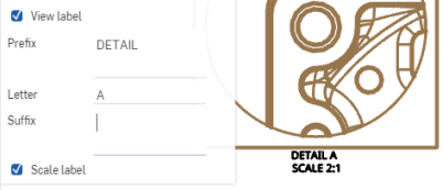
- 比例標籤 - 按一下來顯示視圖下方的比例標籤。
- 顯示草圖外觀 - 核取以在工程圖中顯示來自 Part Studio 或組合件中的草圖外觀。
- 移至圖頁 - 開啟的對話方塊中會有下拉清單列出所有可用的圖頁,選擇要將目前所選視圖移動至的圖頁。
- BOM 表格參考 - 選擇 BOM 表格應該參考的組合件。
- 切割清單表格參考 - 選擇應該參考的切割清單表格。
- 套用父視圖剖切 - 當建立來自「剖切視圖」的「投影視圖」時,切換這個選項來建立有來自父父視圖剖切的「投影視圖」。
如果已插入命名視角但隨後又從工作區中刪除,則命名視角在環境選單清單中會是反灰的。您可以選擇一個不同的視角方位或保留目前視角的原狀。
您也可以開啟視圖來源的 Part Studio 或組合件,然後指定一個比例、旋轉角度、與比例標籤。
選擇 [父比例] 來將視圖的比例與其父視圖比例連結,或選擇 [圖頁比例] 來將視圖比例與圖頁比例相連結。
提示
- 視圖會繞視圖矩形中心旋轉,如果需要,可變更矩形的大小。對於細部放大圖,視圖會繞圍繞細部放大視圖圓的圓心旋轉;可見的幾何會維持不變,圓也會保持同樣的大小。
- 當旋轉角度不是 0 度時,視圖屬性中重新連接對齊是停用的。同樣地,與父視圖重新連接對齊的指令也是停用的。您必須將旋轉角度改變為 0 度才能將視圖與其父視圖重新連接。
- 當旋轉角度改變時,所有的尺寸都會調整。垂直與水平線性尺寸仍會保持為垂直與水平。對齊與旋轉的線性尺寸會保持為與其視圖幾何對齊與旋轉。
- 視圖比例與標籤位置改變至新視圖矩形或細部放大圖圓形下方中心處。
- 使用抑制與父視圖的對齊來移除視圖與其父視圖的對齊。如果沒有附屬項目,也就是說視圖沒有子視圖,則斷開對齊後您可以使用旋轉角度的欄位。不過,如果有其他問題存在而無法旋轉視圖 (也就是說有子項目存在),則無法旋轉視圖。請注意,如果視圖有子視圖存在,就算您選擇了抑制對齊也無法旋轉視圖。
- 使用 Ctrl+C 來複製視圖標籤,並套用註解的預設屬性 (來自「屬性」面板)。使用 Alt+拖曳來複製視圖標籤並同時保持視圖標籤屬性。
使用滑鼠右鍵點按來在任何視圖上開啟環境選單以存取該視圖的指令選項清單。下方列出這些指令選項。請注意,列於此處的各種指令並不適用於所有的視圖類型。
-
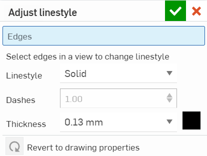
在視圖上按右鍵來開啟環境選單,然後選取 [調整線條樣式] 指令。
-
在視圖的每條邊線上按一下來套用指定的樣式變更;選取的項目會出現在對話方塊中的「邊線」之下。
-
在對話方塊中調整下列項目至您所需的規格:
-
線條樣式 - 從下拉式選單中選擇一個線條樣式。
-
虛線 (如果是虛線的話) - 自訂虛線間的空間。
-
厚度 (用指定的單位)
-
色彩 - 按一下色塊並在色彩對話方塊中相對應調整。
-
-
使用
 關閉對話方塊。
根據預設會隱藏在目前視圖位置中不可見的視圖直線 (隱藏直線)。
若要切換顯示與否,在視圖上按右鍵,然後從環境選單中選擇顯示/隱藏 > 顯示隱藏線 或是隱藏隱藏線:
![選擇視圖,然後從環境選單中選擇 [顯示隱藏線] 的範例](Resources/Images/drawings-tools/views-togglestart.gif)
結果視圖:
![選擇視圖,然後從環境選單中選擇 [顯示隱藏線] 結果的範例](Resources/Images/drawings-tools/views-toggleend.gif)
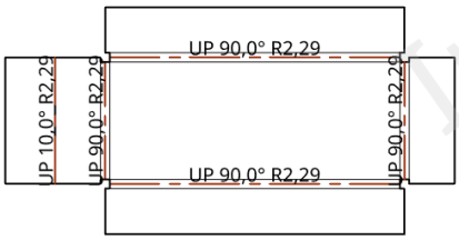
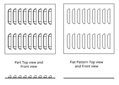
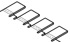
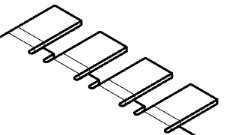
根據預設鈑金展開圖樣視圖的彎折線是可見的。
若要切換顯示與否,在視圖上按右鍵,然後從環境選單中選擇顯示/隱藏 > 顯示彎折線或是隱藏彎折線:
結果視圖:
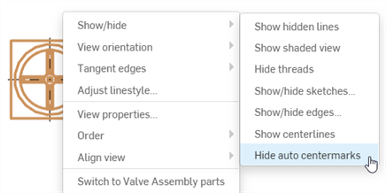
顯示或隱藏加入至視圖中環狀幾何 (鑽孔、圓柱與球形) 上的自動中心線。系統不會隱藏任何使用中心線工程圖工具來加入的中心線。
選擇視圖,然後按右鍵再從環境選單中選擇 [顯示/隱藏] > [隱藏中心線] (或 [顯示中心線]):
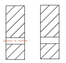
左側顯示自動中心線 (預設),右側則是隱藏的。
相切線是曲線與線性邊線之間形成的邊線;例如,來自圓角或平滑的邊線。
若要選擇相切線的顯示處理方式,請先選擇視圖,然後按右鍵並選取相切線,接著從下列三種模式中選擇:
- 隱藏 - 從工程圖中移除相切線的顯示。
- 實線 - 以實線來顯示相切線,此為系統的預設。
- 影線 - 以斷裂線來顯示相切邊線。

有三種不同的相切線選項,由左到有分別是:實線 (預設)、影線與隱藏。
根據預設零件的塗彩視圖是不可見的。
若要切換顯示與否,請在視圖上按右鍵,然後從環境選單中選擇顯示/隱藏 > 顯示塗彩視圖 或隱藏塗彩視圖 :
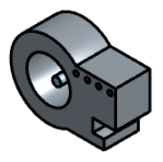
如果父視圖是塗彩的,則細部放大圖也會是塗彩的。您可以獨立於父視圖變更視圖的塗彩,也可以獨立於子視圖變更父視圖的塗彩與否 (在視圖上按右鍵)。
如果有套用至零件上的印花,僅在塗彩視圖的顯示中才會看得到。
根據預設,代表螺紋鑽孔的線條是可見的。
若要切換顯示與否,請在視圖上按右鍵,然後從環境選單中選擇顯示/隱藏 > 顯示 或 隱藏螺紋:
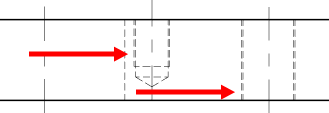
「顯示草圖」對於顯示工程視圖中版金展開圖樣的展平草圖是相當有用的。
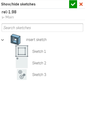
For views of parts, this command shows or hides selected sketches from within a Part Studio. Select the view, then right-click and select Show/hide > Show/hide sketches. When the Show/hide sketches dialog opens, select the sketch from the menu. You can select more than one sketch. This dialog displays all sketches in the Part Studio in which the part was modeled. Selecting the same drawing sketch for each view displays the sketch in each view's perspective.
若要隱藏草圖,請再次開啟顯示/隱藏草圖對話方塊,然後按一下來取消選取一或多個草圖。
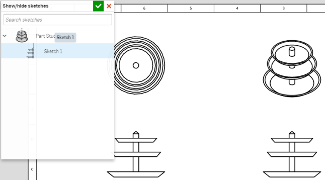
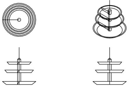
對於組合件的視圖,這個指令會切換來自組合件中所選草圖的顯示與否 (必須先將草圖插入至組合件中)。根據預設會隱藏組合件草圖。
若要切換草圖的顯示與否,請在視圖上按右鍵,然後從環境選單中選擇顯示/隱藏 > 顯示草圖或 隱藏草圖。
當顯示時,所有插入至組合件中的草圖在工程圖中都是可見的。
如果將有草圖點的草圖插入至工程圖中,預設會顯示草圖點。
若要切換顯示與否,請在視圖上按右鍵,然後從環境選單中選擇顯示/隱藏 > 顯示草圖點或是 隱藏草圖點:
![按右鍵然後從環境選單中選擇 [顯示草圖]。](Resources/Images/drawings-tools/show-sketch-points-before-01.png)
若要自訂工程圖中草圖點的外觀與大小,請使用「工程圖屬性」面板內的幾何建構線分頁。
顯示或隱藏工程圖的邊線。在所有工程視圖中皆可使用此功能。
選擇視圖,然後按右鍵再從環境選單中選擇 顯示/隱藏 > 顯示/隱藏邊線 (下方第一個圖片)。顯示/隱藏邊線對話方塊開啟 (下方第二個圖片):
![從環境選單中選擇 [顯示/隱藏邊線]](Resources/Images/drawings/show-hide-edges-01-01.png)

從視圖中選擇您要隱藏的所有邊線。邊線會變為粗的灰色線,表示已被標示為隱藏的。同時會以灰色顯示隱藏線,以幫助您定義要顯示的邊線。如果不小心操作錯誤,再次點按邊線,邊線即會變為黑色 (表示是顯示的),最後按一下對話方塊中的綠色核取記號。任何標示為隱藏的邊線會於視圖中隱藏。
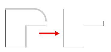
若要顯示任何隱藏的邊線,請反向操作。先選取視圖,然後按右鍵再從環境選單中選擇顯示/隱藏 > 顯示/隱藏邊線,接著選取您要顯示的任何隱藏 (灰色) 邊線,最後點按對話方塊中的綠色核取記號。
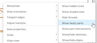
顯示或隱藏已插入至組合件工程視圖中有問題的零件。根據預設會在零件工程圖中顯示有問題的零件,但在組合件工程圖中是預設為隱藏的;渲染這些零件可能會影響效能。
若要切換有問題零件的顯示與否,請在視圖上按右鍵,然後從環境選單中選擇顯示/隱藏 > 顯示有問題的零件 或隱藏有問題的零件。
將草圖插出入剖面視圖中:
- Right-click on the section view and select Show/hide > Show/hide sketches (first image below) to open the Show/hide sketches dialog (second image below):
-
從這裡點按您要插入的一或多個草圖。
- 按一下對話方塊右上角的
 核取記號來將一或多個草圖插入剖面視圖中。
![在環境選單中「顯示/隱藏草圖] 的範例](Resources/Images/show-hide-sketches-01.png)
移除剖面視圖中的草圖:
-
在剖面視圖上按右鍵,然後從環境選單中選擇顯示/隱藏 > 顯示/隱藏草圖。
- 按一下您要移除的一或多個草圖 (注意到系統不會再以藍色強調顯示它們)。
- 按一下對話方塊右上角的
 核取記號來完成一或多個草圖的移除。
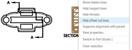
從剖面視圖中您可以切換偏移切割線的顯示與否,請在剖面視圖上按右鍵,然後從環境選單中選擇顯示/隱藏 > 顯示偏移切割線或是 隱藏偏移切割線 :
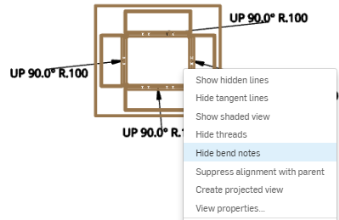
從剖面視圖中您可以切換鈑金展平視圖彎折註解的顯示與否,請在視圖上按右鍵,然後從環境選單中選擇顯示/隱藏 > 顯示彎折註解 或是 隱藏彎折註解:
零件的相交會有虛擬邊線 (在零件相交處繪製的曲線)。根據預設會是不可見的。
將零件的相交保持為隱藏可改善效能。
如果組合件視圖中有超過 20 個零件未能正確顯示,而原因是因為零件間互相干涉,或是相交邊線/面的一些部分在視圖中被錯誤地辨識為隱藏 (或可見),請切換為「顯示零件相交」。
若要切換零件相交的顯示與否,請在視圖上按右鍵,然後從環境選單中選擇顯示/隱藏 > 顯示零件相交或是 隱藏零件相交。
除了切換虛擬邊線的顯示之外 (在零件相交位置繪製的曲線),這個指令同時還原零件的顯示 (由於零件相交或在特定視角方位部分被檔住而無法在視圖中顯示)。
根據預設,在將視圖插入至工程圖中時,零件永遠是可見的。
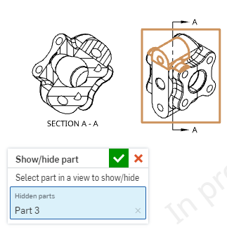
若要切換顯示與否,請在視圖上按右鍵,然後從環境選單中選擇顯示/隱藏 > 顯示/隱藏零件。
系統會開啟一個對話方塊,在選取了「已隱藏零件」欄位的情況下,在視圖中選擇您要隱藏的零件。按一下核取記號 (![]() ) 來接受並關閉對話方塊。例如:
) 來接受並關閉對話方塊。例如:
根據預設會在視圖中隱藏草圖限制條件。
若要切換顯示情形,請在視圖上按右鍵,然後從環境選單中選擇顯示/隱藏 > 顯示限制條件 或隱藏限制條件 :

隱藏限制條件 (左圖),顯示限制條件 (右圖)。
選擇一個視圖,然後按右鍵並將游標移動到顯示狀態來顯示視圖可用顯示狀態的清單。選擇一個狀態。對於所有的父視圖,預設是「全部顯示」。所有子視圖的預設是「遵循父項」的顯示狀態。剖面視圖與細部放大圖僅會有「遵循父項」的顯示狀態。
如果您在建立工程圖之後建立顯示狀態,請更新工程圖來確保使用該顯示狀態。如果您從組合件中刪除一個顯示狀態,則在更新工程圖示會出現一個錯誤訊息:
解出顯示狀態失敗
任何使用已刪除顯示狀態的視圖將會是空白的,但仍會留在工程圖上。已刪除顯示狀態的名稱不會再出現於環境選單中。
選擇一個視圖,然後按右鍵並在「爆炸/位置」上暫留來顯示該視圖可用爆炸或位置狀態的清單。請選擇一個。
如果您在建立工程圖之後建立爆炸視圖,請更新工程圖來使用爆炸。如果您從組合件中刪除一個爆炸視圖,則在更新工程圖示會出現一個錯誤訊息:
解出爆炸視圖失敗
請注意,在爆炸數狀結構的爆炸步驟間移動回溯控制棒並不會影響工程視圖。工程視圖會在爆炸視圖中反映所有爆炸步驟。
選擇一個子視圖,然後按右鍵並選取抑制與父視圖的對齊來斷開由其他視圖衍生的視圖間的自動對齊,以能夠將視圖獨立地放置在工程圖上。
當抑制對齊時,並不會斷開與視圖子項目的對齊。如果視圖有子項目 (或任何對齊),您將無法旋轉視圖。
選擇區域深度剖視、裁剪或輔助視圖,按右鍵並選取編輯剖面、編輯裁剪、或編輯輔助視圖。對於剖視與裁剪視圖,請使用開啟的對話方塊來編輯樣條/圓/多邊形。加入樣條點,將形狀拖曳成新的大小或位置,或是變更其他規格。對於輔助視圖,可使用對話方塊來提供標籤,修改起始的視圖邊線,反轉視圖,或開啟/關閉檢視平面的顯示。
選擇剖面視圖或區域深度剖視圖,按右鍵然後選取編輯剖面線。「編輯剖面線」對話方塊開啟,按一下工程圖的剖面線區域,然後對話方塊中會開啟一組選項,可於其中調整剖面線類型 (ANSI、 ISO 或一般)、樣式、比例、角度與色彩。
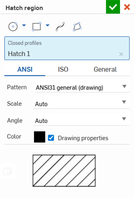
選擇一個剖面或裁剪視圖,按右鍵並選取移除剖面 (或移除裁剪) 來移除區域深度剖視圖或裁剪視圖,然後保留樣條/圓/多邊形以供參考之用。若要移除邊界,請點按邊界來強調顯示,然後按下 Delete 鍵,或按右鍵並選擇 [刪除]。
根據視圖的中心將兩個選取的視圖垂直或水平地對齊。
-
在視圖上按右鍵,或是選擇一個視圖然後按右鍵來啟用環境選單。
-
移動游標至對齊視圖選項上暫留,然後選擇 垂直或水平。
游標會變更為一個選擇游標。
-
選擇另一個要與視圖對齊的視圖。
視圖即會對齊,並結束選擇模式。
對於旋轉的視圖,您可以根據所選的直邊線選擇垂直或水平旋轉它們。可以在視圖的環境選單中找到這些指令:
- 選擇一個視圖。
- 按右鍵來啟用環境選單中。
- 選擇垂直旋轉視圖或水平旋轉視圖。
游標會變更為選取的游標。
- 選擇要用來旋轉視圖的直邊線。
視圖即會旋轉,並結束指令模式。
請參考群組註解。
.
