![]()
在工程圖中按右鍵然後選擇 [工程圖屬性]。
存取「工程圖屬性」面板的圖示是位在工程圖區域的右側。按一下圖示來開啟面板,再按一下來關閉面板。使用這些設定來定義工程圖的預設。可以單獨變更個別的工程圖圖元,但這些設定會以預設套用到工程圖的所有圖元中。在您對工程圖屬性感到滿意之後,可以將工程圖與其設定儲存為範本。關於建立範本的詳細資訊,請參考自訂工程圖範本。
下方的圖例顯示這個圖示,就位在工程圖視窗右側的中下方,以紅色輪廓線框出:
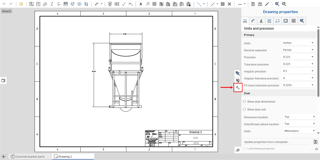
「屬性」面板有多個分頁,分別說明如下。

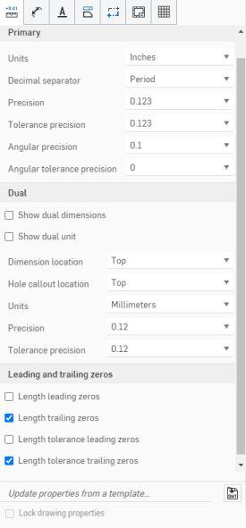
按一下「工程圖屬性」面板上方標示為 [單位與精度] 的第一個圖示來編輯工程圖的單位與精度。
定義工程圖的預設主要單位。可以編輯下列項目的格式:
- 單位 - 工程圖的雙重單位。可以選擇的有:英吋、英吋分數、毫米、以及英呎與英吋。
- 對工程圖單位的管理是與 Part Studio 和組合件的工作區單位獨立的 。
- 英呎與英吋僅可於工程圖中使用;不可用於工作區的單位。
- 小數分隔符號 - 用來做為小數分隔符號的預設字元。可選擇:英文逗號或句號。
- 精度 - 除了列在「屬性」飛出視窗中數字之外所有數字的精度。可以選擇:0 到最多 6 位小數位數,或 0 到 1/256 間的分數。
- 公差精度 - 幾何公差的精度。選擇介於:0 到最多 6 位小數位數,或 0 到 1/256 間的分數。
- 角度精度 - 角度測量值的精度。選擇介於:0 到最多 6 位小數位數。
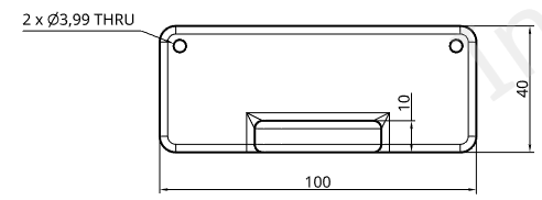
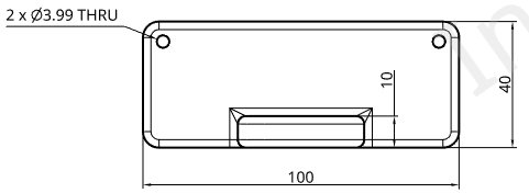
使用預設屬性的原始工程圖 (上圖),將小數分隔符號改設為「小數」(下圖)
- 角度公差精度 - 角度的公差精度。選擇介於:0 到最多 6 位小數位數。
- 配合類別公差精度 - 角度的配合類別公差精度。選擇介於:0 到最多 6 位小數位數。
指定是否要在工程圖中顯示雙重尺寸和/或雙重單位。您可以參考視圖指定尺寸的位置,也可以指定單位類型、小數位數的精度與公差精度。
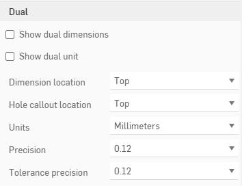
- 核取顯示雙重尺寸來以預設的文件單位以及指定的第二單位來顯示工程圖中的所有尺寸。請指定要在何處顯示第二尺寸,可以是在預設單位的上方或底部:


- 核取顯示雙重單位以顯示雙重尺寸的單位;否則只會顯示尺寸而不顯示測量的單位。
- 尺寸位置 - 指定放置雙重尺寸的位置:初始尺寸的上方或下方
- 鑽孔標註位置 - 選擇於何處放置鑽孔標註雙重尺寸:初始尺寸的上方、底部、左側或右側。
- 單位 - 指定雙重尺寸的單位:除了為最初尺寸標籤指定的單位之外,這個清單會包含所有的測量單位。
- 精度 - 雙重尺寸的精度。可選擇:0 到最多 6 位小數位數,或 0 到 1/256 間的分數。
- 公差精度 - 幾何公差的精度。選擇介於:0 到最多 6 位小數位數,或 0 到 1/256 間的分數。
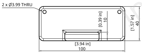
選取了顯示雙重尺寸、顯示雙重單位的工程圖,其中單位是設定為「英吋」,精度則是設定為 '0.12' (兩位小數位數)
使用這些設定來建立長度前置與尾隨零的格式。
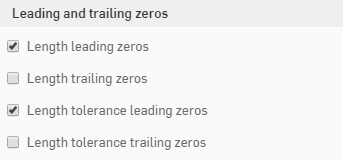
- 長度前置零 - 選取來包括長度的前置零。
- 長度尾隨零 - 選取來在長度中包含尾隨零。
- 長度公差前置零 - 選取來包括公差的前置零。
- 長度公差尾隨零 - 選取來包括公差的尾隨零。
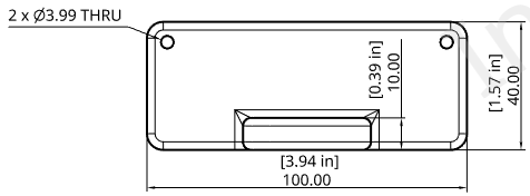
長度尾隨零設定為開啟的工程圖
若要存取「尺寸」功能表,按一下「工程圖屬性」面板圖示列中的第二個圖示。
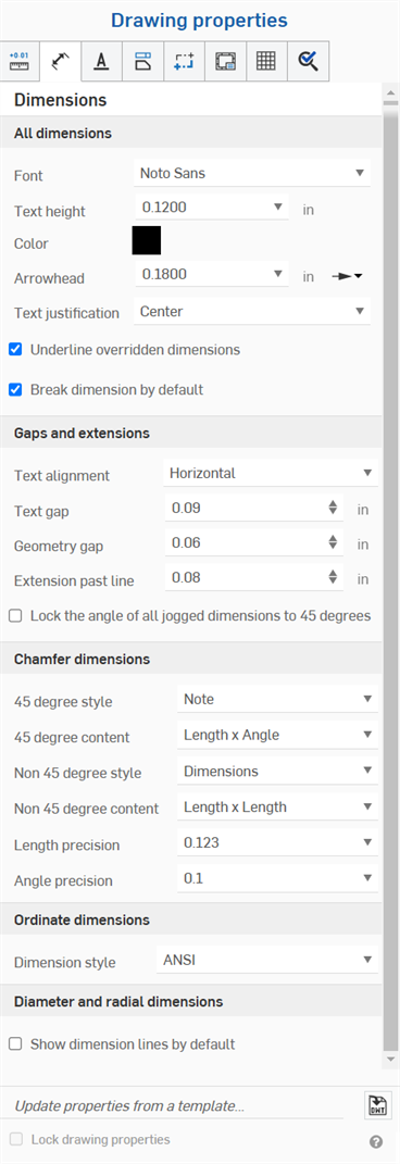
使用這個分頁來編輯工程圖的字型、文字高度、色彩、文字對齊、文字間隙、幾何間距等。按一下右側功能表的下拉式功能表箭頭並選擇一個選項來變更各個選項。
- 字型 - 選擇要使用的尺寸文字字型。
- 文字高度 - 選擇要使用的尺寸文字大小。
- 色彩 - 若要編輯任何工程圖圖元的色彩,按一下「工程圖屬性」面板中的色塊以存取色彩對話方塊:
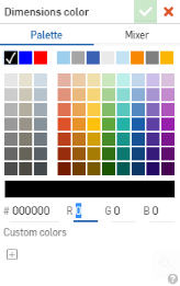
- 選擇調色盤來選取色彩或輸入一個十六進位或 RGB 代碼。使用色彩混合器面板來拖曳至大約的色彩區域,然後輸入特定的十六進位或 RGB 代碼。
在調色盤或色彩混合器面板中,您可以按一下自訂色彩下方的加號來將目前指定的色彩值儲存為自訂色彩以供日後使用。
- 箭頭 - 變更尺寸的箭頭大小。箭頭的長度可以是任何介於 0.004 英吋與 393.7 英吋間的值。
- 箭頭類型 - 選擇無箭頭、實心箭頭、空心箭頭、開放箭頭、傾斜標示或填滿的點。
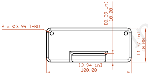

- 箭頭類型 - 選擇無箭頭、實心箭頭、空心箭頭、開放箭頭、傾斜標示或填滿的點。
- 文字調整 - 變更工程圖中所有註解與尺寸文字的調整。從「左」、「中心」、「右」或「自動對齊」中選擇。
- 加底線於重置尺寸 - 取消核取這個方塊來從目前所有重置尺寸中移除底線格式。
- 預設斷開尺寸 - 預設是核取的,這樣會在重疊的尺寸線間建立空間。取消核取並不會改變現有的尺寸,但會決定之後所建立尺寸的預設狀態。
工程圖中尺寸色彩設定為紅色,字型改為 APMONO,文字高度增至 4.5,箭頭長度的設定是 4.5000。第二個圖片顯示使用「傾斜」的箭頭類型。
使用這個分頁來編輯您工程圖的文字對齊_文字間距、幾何間距、超出尺寸界線,並將所有轉折尺寸的角度鎖定為 45 度:
- 文字對齊 - 指定要將尺寸文字與尺寸線對齊,或是與工程圖圖頁的底部邊線水平對齊。
- 文字間距 - 設定工程圖中文字間距的測量值。
- 幾何間距 - 設定工程圖中幾何間距的測量值。
- 超出尺寸界線- 設定尺寸界線延伸超出文字的距離。
- 鎖住所有轉折尺寸的角度至 45 度 - 核取此方塊來將工程圖中所有轉折尺寸的角度鎖定為 45 度。
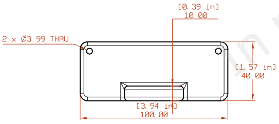
工程圖中文字對齊設定為「水平」,文字間距與幾何間距設定為 0.75,超出尺寸界線增加至 1.5
關於使用工具的詳細資訊,請參考尺寸 - 倒角尺寸。
使用這些屬性來對工程圖中的倒角尺寸進行變化。您可以指定:
- 45 度樣式 - 選擇要出現的是註解或尺寸
- 45 度內容 - 角度 x 長度;長度 x 角度;長度 x 長度;C 長度
- 非 45 度樣式 - 尺寸;註解
- 非 45 度內容 - 角度 x 長度;長度 x 角度;長度 x 長度
- 長度精度 - 在長度值中數字的位數
- 角度精度 - 在角度值中數字的位數

變更工程圖座標尺寸樣式。
-
ANSI - 顯示來自座標尺寸的導引線。
-
ISO - 顯示來自座標尺寸的導引線,並有額外的箭頭會連接從原點開始增加的座標值。
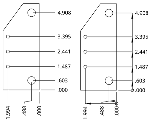
工程圖中的左側為 ANSI 座標尺寸樣式,右側為 ISO 樣式
如果當您建立新工程圖時使用 ANSI 或 ISO 範本,會分別將座標尺寸樣式預設為 ANSI 或 ISO。
-
預設顯示尺寸線 - 顯示圓或弧內的半徑與直徑尺寸線。根據預設,建立使用 ISO 範本的工程圖時會核取這個選項,建立使用 ANSI 範本的工程圖時則會取消核取。取消核取並不會改變現有的尺寸,但會決定之後所建立尺寸的預設狀態。

核取「顯示尺寸線」(左圖) 與未核取「顯示尺寸線」的環狀工程圖 (右圖)。
若要存取「註記」的屬性,請按一下「工程圖屬性」面板上方的第三個圖示。可從該處編輯工程圖中的字型、文字高度、箭頭長度和類型、以及每種註記類型的色彩:您可以一次提供所有註記的預設,或分別設定註解、標註、基準、幾何公差、表面加工符號、熔接符號、鑽孔標註與彎折註解 (鈑金)。

對各種工程註記圖元類似的屬性將說明如下,特定於某一註記類型的屬性將於這個部分後的次標題中說明。
- 字型 - 選擇每個註記類型要使用的字型。
- 文字高度 - 選擇每個註記類型的大小。
-
色彩 - 若要編輯任何註記項目的色彩,按一下相對應的色塊以存取色彩對話方塊:

- 選擇調色盤來選取色彩或輸入一個十六進位或 RGB 代碼。使用色彩混合器面板來拖曳至大約的色彩區域,然後輸入特定的十六進位或 RGB 代碼。
在調色盤或色彩混合器面板中,您可以按一下自訂色彩下方的加號來將目前指定的色彩值儲存為自訂色彩以供日後使用。
指定所有註解屬性的預設,包括字型、文字高度與色彩。
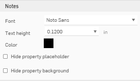
您也可以指定:
-
隱藏屬性預留位置 (在標題方塊中以 ---- 顯示)
-
隱藏屬性背景 (如在標題方塊中所示,預設是灰色的)
請注意,根據預設,所有匯出的工程圖不再包含工程圖與圖頁屬性的預留位置 ("----")。
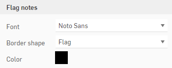
指定所有旗標註解的預設,包括「字型」、「邊框形狀」與「色彩」。
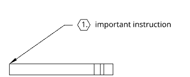
指定所有標註的預設,要放置在空間中或是附加至幾何上,並包括字型、文字高度、色彩、文字調整 、堆疊方向、與堆疊間隙大小。

工程圖中的標註是與 BOM 的「項目編號」欄相對應
指定所有基準屬性的預設,包括字型、文字高度、基準大小 (三角形的大小) 與色彩。
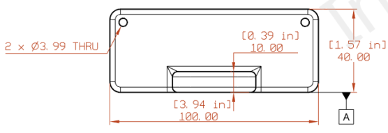
指定所有幾何公差的預設,包括字型、文字高度與色彩。

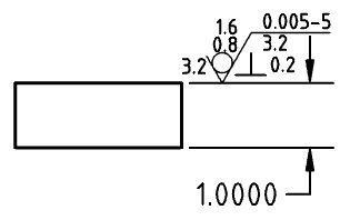
指定所有表面加工符號的預設,包括字型、文字高度與色彩。
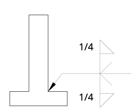
在「註記」功能表的底部變更熔接符號的標準。這個功能表會變更用於工程圖中熔接符號的預設標準。這個標準是與工程圖標準分開獨立的,因此不會改變工程圖的標準。例如,在使用 ANSI 標準的工程圖中,您可以變更這個設定來在工程圖中全部使用 ISO 熔接符號。
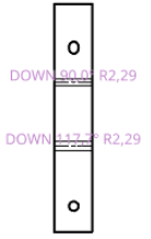
變更附加至鈑金視圖上彎折註解的格式 (包括字型、文字高度與色彩)。工程圖中的彎折註解是來自在 Part Studio 中指定的彎折規格:
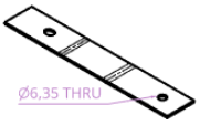
變更附加至鈑金視圖上鑽孔標註的格式 (包括字型、文字高度、色彩、與指標)。鑽孔標註是經由「尺寸」下拉式功能表中的「鑽孔標註」工具 ![]() 來套用至鈑金展開圖樣工程圖中。
來套用至鈑金展開圖樣工程圖中。
若要存取「視圖」功能表,請按一下「工程圖屬性」面板上方的第四個圖示。在這個功能表中您可以編輯工程圖的投影角度,顯示邊線、相切邊線、隱藏邊線、切割線、箭頭、視圖標籤與其他項目的色彩與粗細。

對各種工程視圖類似的屬性將說明如下,特定於某一視圖類型的屬性將於這個部分後的次標題中說明。
- 直線 - 選擇一個線條樣式、粗細、與色彩。
- 箭頭 - 選擇一個箭頭大小與樣式。
- 標籤 - 選擇一個字型、字型大小、格式、與色彩。
- 色彩 - 若要編輯任何註記項目的色彩,按一下相對應的色塊以存取色彩對話方塊:

- 選擇調色盤來選取色彩或輸入一個十六進位或 RGB 代碼。使用色彩混合器面板來拖曳至大約的色彩區域,然後輸入特定的十六進位或 RGB 代碼。
在調色盤或色彩混合器面板中,您可以按一下自訂色彩下方的加號來將目前指定的色彩值儲存為自訂色彩以供日後使用。
在此處為所有的視圖類型選擇預設:剖面視圖、細部放大圖、斷開視圖與展開圖樣視圖:
- 投影角度 - 指定要使用的投影方式
- 顯示邊線 - 指定代表可見邊線的線條粗細與色彩
- 視圖標籤 - 指定所有視圖標籤的字型、大小、字型處理方式與色彩
設定隱藏閾值之下的特徵藉以簡化工程圖中的幾何,這個設定僅會影響新近插入的視圖。
-
無 - 不會套用簡化設定。
-
自動 - 預設。根據零件的幾何來找出最佳的視圖簡化設定,並自動使用這些設定來顯示零件或組合件。
-
絕對 - 輸入工程圖長度單位的數字設定小於這個值的特徵會在視圖中被簡化。如果整個零件小於這個閾值,這些零件都會從視圖中消失。這對於移除在工程圖操作中不需要的額外細節是相當有用的 (例如,為數眾多的小特徵或零組件)。
-
與 studio 比例 - 輸入 Part Studio 或組合件大小的百分比,小於該值的特徵會在視圖中被簡化。如果整個零件小於這個閾值,這些零件都會從視圖中消失。這對於移除在工程圖操作中不需要的額外細節是相當有用的 (例如,為數眾多的小特徵或零組件)。
-
與零件比例 - 輸入零件大小的百分比,小於該值的特徵會在視圖中被簡化。這個設定是希望在簡化零件細節的同時將零件保留在視圖中。如果您想要確定所有的零件都出現在視圖中以便建立細節 (例如,放置標註),則此設定是相當有用的。
指定代表隱藏邊線的線條粗細與色彩,以及虛線的間距。
指定代表相切線的線條粗細與色彩,以及虛線的間距。
指定爆炸視圖中爆炸線的粗細,以及虛線的間距。
指定這些項目的預設:
- 剖面線圖案 - 指定剖面線標記的預設類型與圖案
- 剖面線 - 指定剖面線標記的預設線條大小與色彩
- 切割線 - 指定切割線的預設線條大小與色彩
- 箭頭 - 指定預設大小與箭頭類型 (實心、空心或開放)
- 切割線標籤 - 指定所有切割線標籤的字型、大小、字型處理方式與色彩
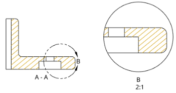
在上方圖例中剖面視圖的剖面線變為金色 (變更也會沿續至細部放大圖中),切割線上的箭頭改用較大的尺寸
指定這些項目的細節:
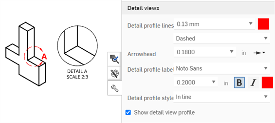
- 細部輪廓線 - 指定細部輪廓線的預設線條大小、色彩、與樣式 (影線、虛線、或實線)。
- 箭頭 - 指定預設大小與箭頭類型 (實心、空心或開放)。
- 細部輪廓標籤 - 指定所有細部輪廓標籤的字型、字型大小、樣式、與色彩。
- 細部輪廓樣式 - 選擇平行、連接、或導線。
- 細部放大圖輪廓 - 取消選擇核取方塊來移除細部放大圖周圍的輪廓線。
- 顯示細部放大圖輪廓 - 顯示顯示細部放大圖的輪廓。
- 將邊框裁剪至幾何 - 根據預設會顯示細部放大圖的邊框。啟用這個選項會僅顯示細部放大圖的幾何,而不顯示邊框。
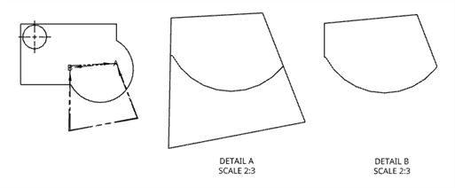
原始的前視圖 (左),停用「將邊框裁剪至幾何」的細部 A (中);啟用「將邊框裁剪至幾何」的細部 B (右)。
指定這些項目的細節:
- 顯示視圖參考指標 - 顯示/隱藏視圖參考指標。
- 視圖參考格式 - 按一下格式影像來在線條樣式與箭頭樣式之間轉換視圖參考指標的格式。
- 檢視線 - 指定預設視圖參考指標線條的粗細與色彩。
- 箭頭 - 指定預設大小與箭頭類型 (實心、空心或開放)。
- 檢視線標籤 - 指定所有檢視線標籤的字型、大小、字型處理方式與色彩。
- 視圖標籤前置詞 - 輸入顯示在視圖標籤之前的前置詞。
- 視圖標籤樣式 - 在 A-A 與 A 之間選擇。
- 視圖標籤後置詞 - 輸入顯示在視圖標籤之後的後置詞。
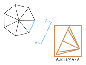
以棕色方框顯示的輔助視圖,檢視平面與參考指標以藍色顯示,標籤則是黑色的。
您也可以使用「輔助視圖」的箭頭樣式做為參考點來建立尺寸或線到線的角度尺寸。在建立「輔助視圖」之後,開啟屬性面板 > 視圖 > 輔助視圖,然後選擇「箭頭樣式」做為「視圖參考格式」,之後您就可以使用「尺寸」工具建立角度尺寸。
指定折斷線的預設線條粗細與色彩。
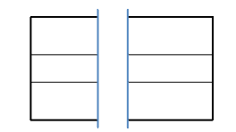
在上方的圖例中折斷線的粗細是 0.50mm,顏色則是藍色。
指定內部與外部螺紋的螺紋樣式、粗細、與色彩。您也可以指定 ANSI 螺紋的 dash 長度比例。
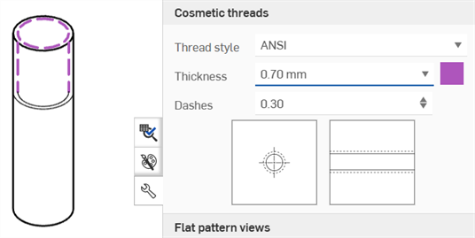
對於鈑金展開圖樣的工程圖,請指定下列的項目:
-
所有彎折線 - 調整所有彎折線的粗細
-
上彎折線 - 調整上彎折線的樣式 (實線、虛線、或中心線 (預設)) 與色彩。
-
下彎折線 - 調整下彎折線的樣式 (實線、虛線、或中心線 (預設)) 與色彩。
-
彎折相切邊線 - 調整彎折相切邊線的粗細與色彩。
-
埋頭孔/沉頭孔上方 - 調整埋頭孔/沉頭孔上方線條的樣式 (實線 (預設)、虛線、或中心線) 與色彩。
-
埋頭孔/沉頭孔下方 - 調整埋頭孔/沉頭孔下方線條的樣式 (實線 (預設)、虛線、或中心線) 與色彩。
-
成形撕裂 - 調整成形撕裂線條的樣式 (實線 (預設)、虛線、或中心線) 與色彩。
-
成形上方 - 調整成形上方線條的樣式 (實線、虛線、或中心線 (預設)) 與色彩。
-
成形下方 - 調整成形下方線條的樣式 (實線、虛線、或中心線 (預設)) 與色彩。
-
成形中心符號線 - 調整成形中心符號線條的樣式 (實線 (預設)、虛線、或中心線) 與色彩。
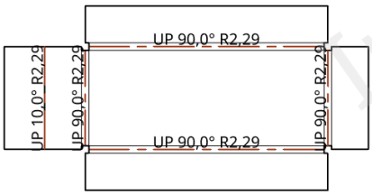
在上方的圖例中所有的彎折線有 0.50mm 的值,且上彎折線的色彩是指定為紅色
若要存取「幾何建構線」功能表,按一下「工程圖屬性」面板上方的第五個圖示。在這個功能表中您可以編輯工程圖中心線與中心符號線的色彩與粗細,以及工程圖中虛擬交角的樣式、色彩與粗細。使用 Part Studio 中草圖的部分來編輯帶入工程圖中的草圖格式。
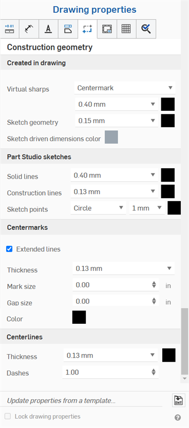
- 在工程圖中建立 - 指定在工程圖中所建立幾何建構線的預設:
- 虛擬交角 - 如下圖所示個別指定所有虛擬交角 (例如中心符號線或邊線延伸) 的顯示處理方式:
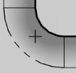
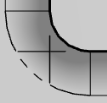
- 草圖幾何 - 指定加入至工程圖中所有草圖的預設線條大小與色彩。
- 草圖從動尺寸色彩 - 指定加入至工程圖中的所有從動尺寸的色彩。
- 虛擬交角 - 如下圖所示個別指定所有虛擬交角 (例如中心符號線或邊線延伸) 的顯示處理方式:
- Part Studio 草圖 - 指定以 Part Studio 草圖所帶入幾何的預設。
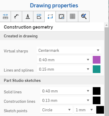
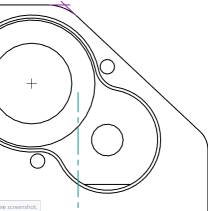
上方的圖例顯示在對話方塊中為幾何建構線做出的選擇;右邊的圖片顯示紫色的虛擬交角與綠色的邊線延伸
-
中心符號線 - 為自動或手動的中心符號線指定預設的線條大小與色彩、粗細、符號大小、間距大小以及是否要延伸線條。為環狀複製排列中心符號線指定是否要顯示螺栓圓圈、輻射線 和/或複製排列中心符號線。
-
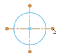
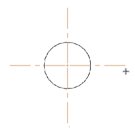
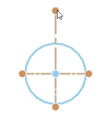
若要修改自動或手動中心符號線的長度,請啟用延伸線。將游標移動至中心符號線上暫留以顯示每條線尾端的抓點。在其中一個抓點上按一下並向外或向內拖曳,然後將抓點放置在新的位置上。所有的線條會同時移動,若要單獨移動一條線,請按住 Shift,然後拖曳後放置。
移動游標至線上暫留以顯示抓點 (上方中第一個圖片所示), 按一下並拖曳抓點來向外延伸所有中心符號線 (上方中第二個圖片所示),按住 Shift,然後按一下並拖曳抓點來向上延伸單一線條 (上方中第三個圖片所示)
-
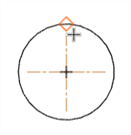
當拖曳自動或手動中心符號線抓點到邊線上時,會顯示一個紅色菱形的抓取點,讓您可以將中心符號線延伸線放置在這個抓取點的位置上 (請件下方圖片)。僅會在同時移動所有中心符號線延伸線時顯示抓取點。當 Shift+拖曳抓點來移動單一延伸線時不會顯示。
-
- 中心線 - 指定預設的線條大小與色彩,,以及虛線的間距。
若要存取「格式」功能表,按一下「工程圖屬性」面板上方內的第六個圖示。這個功能表會啟用 / 停用在工程圖邊框框架、邊框區域與標題區塊中對物件的選取。對新工程圖的預設是「鎖定」的;意即您無法馬上在標題區塊、邊框或邊框區域中選擇物件。
一開始時工程圖的此項屬性應是設定為解除鎖定的,這樣使用者可以選擇在標題區塊或邊框中的物件。
如果欄位值變更,則當標題區塊被鎖住時,會更新標題區塊的內容。
如果您將一個圖元移動到標題區塊、邊框或邊框區域中,且格式是鎖住的,則您必須先將圖元移回工程圖中才能編輯圖元。
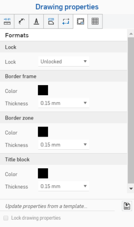
- 已鎖定 - 鎖定或解除鎖定標題區塊來不允許或允許編輯。
- 邊框框架 - 指定工程圖內邊框的色彩與粗細
- 邊框區域 - 指定工程圖邊框區域內標籤的色彩與粗細
- 標題區塊 - 指定標題區塊的線條色彩與內容,以及線條的粗細
標題區塊與邊框中的灰色圖元會沿襲使用其來自文件資料或屬性的值;不過,在圖元上按右鍵可存取該圖元的環境選單。選擇編輯註解來編輯圖元。移動滑鼠至一欄位上暫留 (或點按欄位) 可查看相對應的屬性。如果需要,您可以刪除欄位 (屬性) 並插入自己的文字。使用編輯註解方塊中的插入工程圖屬性圖示來插入不同的屬性:
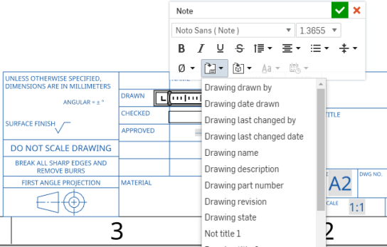
這個圖例顯示正在編輯標題區塊中的欄位 (從環境選單中選擇 [編輯註解]),然後使用 [插入工程圖屬性] 指令來插入新的欄位
- 在匯出的過程中會加入至相對應圖層的元素:標題區塊、邊框框架、或邊框區域。
- 不會將工程圖圖層包括在工程圖的 DWT 匯出中。
- 當格式是設定為已鎖定時,會鎖住邊框框架、邊框區域、與標題區塊圖層。
- 邊框框架、邊框區域、與標題區塊圖層可以有不同的預設色彩與線條粗細。
- 當匯出至 DWG/DXF 時,在邊框框架、邊框區域、與標題區塊圖層中的內容會位在特定的圖層中 (例如,BORDER_FRAME, BORDER_ZONES, TITLE_BLOCK)。
- 請注意,較舊版本的 DWG/DXF 格式可能不會完全支援圖層。
- 當工程圖圖頁大小變更時,標題區塊不會改變。不過,邊框框架與邊框區域會以較大/較小的大小或是更多或更少的區域來重新繪製。
- 在圖頁大小變更或圖頁格式置換時,並不會取代工程圖圖層中的所有內容。
若要存取「表格」功能表,請按一下「工程圖屬性」面板上方的倒數第二個圖示。您可以變更材料表 (BOM) 以及您在工程圖中建立的所有其他表格,例如鑽孔表格。

- 所有表格 - 指定所有表格的預設值,包括:
- 水平填補 - 指定表格儲存格的預設水平厚度填補值,預設值是 0.06 英吋。
- 垂直填補 - 指定表格儲存格的預設垂直厚度填補值,預設值是 0.06 英吋。
- BOM 表格 - 指定材料表的預設值,包括:
- 線條粗細 - 指定線條的預設粗細。
- 字型 - 指定預設字型的類型。
- 標頭列文字 - 指定標頭列的預設字型大小、字型處理方式與色彩。
- 內容列文字 - 指定內容列的預設字型大小、字型處理方式與色彩。
- 自訂表格 - 指定自訂表格的預設值,包括:
- 線條粗細 - 指定線條的預設粗細。
- 字型 - 指定預設字型的類型。
- 標頭列文字 - 指定標頭列的預設字型大小、字型處理方式與色彩。
- 內容列文字 - 指定內容列的預設字型大小、字型處理方式與色彩。
- 切割清單表格 - 指定切割清單表格的預設值,包括:
- 線條粗細 - 指定線條的預設粗細。
- 字型 - 指定預設字型的類型。
- 標頭列文字 - 指定標頭列的預設字型大小、字型處理方式與色彩。
- 內容列文字 - 指定內容列的預設字型大小、字型處理方式與色彩。
- 鑽孔表格 - 指定鑽孔表格的預設值,包括:
- 線條粗細 - 指定線條的預設粗細。
- 字型 - 指定預設字型的類型。
- 標頭列文字 - 指定標頭列的預設字型大小、字型處理方式與色彩。
- 內容列文字 - 指定內容列的預設字型大小、字型處理方式與色彩。
- 指標樣式 - 選擇鑽孔指標的標準:ANSI 或 ISO。
- 指標箭頭 - 輸入或選擇指標箭頭的大小。
- 指標線條 - 選擇線條的粗細與色彩。
- 標記 - 指定鑽孔標記文字的特性:字型、大小、格式 (粗體、斜體或無格式)、與色彩。
- 修訂版表格 - 指定修訂版表格的預設值,包括:
- 線條粗細 - 指定線條的預設粗細。
- 字型 - 指定預設字型的類型。
- 標題列文字 - 指定表格標題列的預設字型大小、字型處理方式、與色彩。
- 標頭列文字 - 指定表格標頭列的預設字型大小、字型處理方式、與色彩。
- 內容列文字 - 指定表格內容列的預設字型大小、字型處理方式、與色彩。
- 修訂版標註 - 指定標註的預設形狀、字元的數量,以及字型、大小、色彩、與處理方式。
- 表格 - 指定在工程圖中所建立表格的預設值,包括:
- 線條粗細 - 指定線條的預設粗細。
- 字型 - 指定預設字型的類型。
- 標題列文字 - 指定表格標題列的預設字型大小、字型處理方式、與色彩 (如果適用的話)。
- 標頭列文字 - 指定表格標頭列的預設字型大小、字型處理方式、與色彩 (如果適用的話)。
- 內容列文字 - 指定表格內容列的預設字型大小、字型處理方式、與色彩。
若要獨立於表格屬性之外編輯表格的儲存格,可點按儲存格空白區域來開啟「儲存格」編輯面板:

連按兩下表格中的文字來在表格屬性之外獨立編輯任何儲存格中的文字:

若要存取檢查項目功能表,請按一下「工程圖屬性」面板上方的最後一個圖示。您可以變更加入到工程圖中檢查項目的外觀。
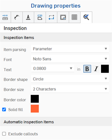
- 項目剖析 - 指定檢查項目剖析的預設行為。「參數」(預設) 會將鑽孔標註與倒角尺寸分開為個別的參數 (請見下方左圖範例);「列」會將鑽孔標註與倒角尺寸合併為一個單一的列 (請見下方右圖範例)。在加入檢查項目時,取決於所做的選擇,系統會強調顯示列或參數:

- 字型 - 指定檢查項目的預設字型類型。
- 文字 - 指定顯示為檢查項目一部分的文字大小與處理方式。
- 邊框形狀 - 選擇檢查項目所需的形狀。
- 邊框大小 - 選擇檢查項目形狀所需的大小。
- 邊框色彩 - 選擇檢查項目的色彩。
- 實心填滿 - 核取這個方塊來指定實心的檢查項目,並選擇色彩。
- 排除標註 - 根據預設,如果使用自動檢查項目,在建立標註時,會將檢查項目編號指定給標註。如果您要排除將檢查項目編號指定給標註,請核取這個方塊。
您可以使用「參數」與「列」的組合。例如,使用預設的「項目剖析」> 「參數」設定,將兩個檢查項目加至兩個倒角尺寸參數中,然後將「項目剖析」轉換為「列」,再加入第三個檢查項目到倒角尺寸列中。
在 Onshape 中您可以使用「工程圖屬性」面板底部的功能 (下圖中以紅色輪廓線框出) 來匯入您已建立的工程圖範本以變更工程圖的屬性。您也可以使用 [鎖住工程圖屬性] 核取方塊來避免意外編輯工程圖屬性。
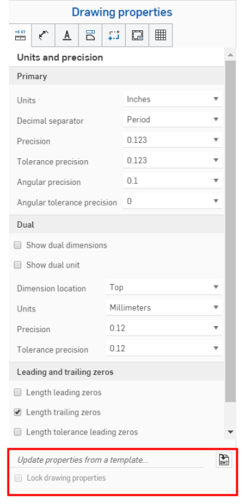
若要使用現有的 Onshape 工程圖範版來更新屬性,請開啟「工程圖屬性」面板。
按一下「更新來自範本的屬性...」右側的「選擇一個 DWT」圖示 ![]() 來開啟「選擇一個 DWT」對話方塊:
來開啟「選擇一個 DWT」對話方塊:
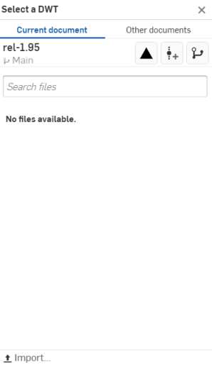
從目前的文件中選擇一個 DWT
- 按一下對話方塊上方的
 。
。 - 於搜尋檔案列中輸入來找出檔案,或從下方的清單中選擇一個項目。
- 若要從您的桌面電腦匯入一個 DWT,按一下對話方塊底部的
 [匯入],接著選擇要匯入的檔案,然後按一下 [開啟]。
使用對話方塊最上方「其他文件」之下的三個圖示,分別說明如下:
![]() 檢視已發行的項目 - 按一下「檢視已發行的項目」圖示來列出所有已發行的項目以供選擇。
檢視已發行的項目 - 按一下「檢視已發行的項目」圖示來列出所有已發行的項目以供選擇。
![]() 建立版本 - 按一下「建立版本」圖示來開啟「建立版本」對話方塊:
建立版本 - 按一下「建立版本」圖示來開啟「建立版本」對話方塊:

調整您版本的名稱和/或說明,然後按一下 建立 來建立版本,或按一下 建立版本並編輯屬性 來開啟「屬性」對話方塊:
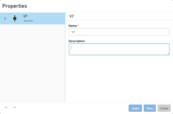
調整您版本的屬性,按一下 套用 來套用變更,或按一下 儲存 來套用變更並關閉「屬性」對話方塊。
按一下 關閉 來關閉「屬性」對話方塊而不套用任何變更。
![]() 版本圖表 - 按一下「版本圖表」圖示來從版本圖表中選擇一個文件不同的版本。
版本圖表 - 按一下「版本圖表」圖示來從版本圖表中選擇一個文件不同的版本。
從其他文件中選擇一個 DWT
- 按一下對話方塊上方的
 。
。 - 使用搜尋列,或是點按下方選項之一來從 Onshape 的其他文件選擇一個 DWT。
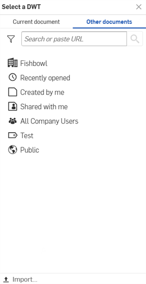
![]() 本人所擁有 - 從您擁有的文件中選擇一個 DWT。
本人所擁有 - 從您擁有的文件中選擇一個 DWT。
![]() /
/ ![]() /
/ ![]() Enterprise/Classroom/Company - 在您的企業/課堂/公司中選擇一個 DWT。
Enterprise/Classroom/Company - 在您的企業/課堂/公司中選擇一個 DWT。
![]() 最近開啟的 - 從您最近開啟的文件中選擇一個 DWT。
最近開啟的 - 從您最近開啟的文件中選擇一個 DWT。
![]() 本人所建立 - 從您所建立的文件中選擇一個 DWT。
本人所建立 - 從您所建立的文件中選擇一個 DWT。
![]() 與本人共享 - 從與您共享的文件中選擇一個 DWT。
與本人共享 - 從與您共享的文件中選擇一個 DWT。
- 若要從您的桌面電腦匯入一個 DWT,按一下對話方塊底部的
 [匯入...],接著選擇要匯入的檔案,然後按一下 [開啟]。
在您匯入工程圖範本之後,系統會自動更新屬性。
使用複製格式來將一個尺寸或註記的格式套用至其他的尺寸或註記中。
