Render Studio インターフェイス - シーンリスト
![]()
のみ利用可能
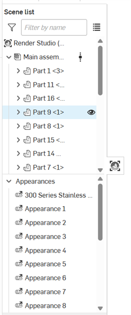
ページの左側にあるシーンリストには、現在の Render Studio シーンのパーツ、Part Studio、およびアセンブリ情報が表示されます。
シーンリストでオプションを選択すると、右側のシーン、外観、および環境パネルに、関連するサブメニューと編集可能なパラメータが表示されます。パラメータオプションの包括的なリストについては、[シーン] パネル、[外観] パネル、および [環境] パネルの各セクションを参照してください。
外観パネルには、シーンリストアイテムが 1 つ選択されている場合のみ使用可能なパラメータが表示されます。スペースバーを押してすべてのアイテムの選択を解除し、シーンリストから 1 つのアイテムを選択します。
シーンリスト内のトランスフォームとプロジェクターを除くすべてのエンティティを複数選択 (グループ選択でまとめて選択) できます。トランスフォームとプロジェクターは単一の選択のみです。
シーンリストはスクロール可能な 2 つのセクションに分かれています。
-
Scene list geometry (upper section) - Contains all the geometry in the scene, as well as any Transforms, Projectors, and Volumes (Render Studio Advanced only).
-
外観 (下部) - シーン内のジオメトリで使用されるすべての外観が含まれます。
シーンリストの幅を調整するには、その右端にカーソルを合わせます。カーソルが両端の矢印に変わったら、ドラッグしてサイズを変更します。
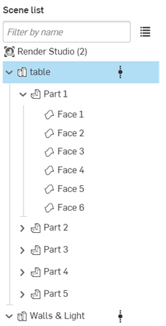
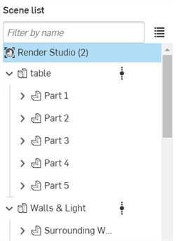
シーンリストはシーンに対して階層的にアプローチし、レベルの観点から考慮できます。たとえば、下の画像では、Render Studio が最上位に、テーブルが Render Studio の 1 レベル下、パーツ 1 がテーブルパーツの 1 レベル下にあります。
このレベルの概念は、優先順位を設定するうえで重要です。最上位のレベルのプロパティは、その下のすべてのレベルよりも優先されます。最上位レベルでプロパティが設定されておらず、次のレベルで設定されている場合、そのプロパティが優先され、そのプロパティがすべての下位レベルに適用されます。この規則の例外は、上位レベルのプロパティにオーバーライドが設定されている場合です。オーバーライドが設定されている場合、それより下のすべてのレベルがオーバーライドされ、代わりにこの最上位レベルのプロパティが使用されます。
たとえば、下の図では、テーブル Part Studio にプロパティセットがある場合、その下のすべてのエンティティ (パーツ 1 からパーツ 5) がこのプロパティを使用します。一方、テーブルにプロパティが設定されておらず、パーツ 1 が設定されている場合は、パーツ 1 に設定されているプロパティがその下のすべてのレベルに使用されます。1 つ上のレベル (テーブルなど) にオーバーライドが存在する場合、いずれかにプロパティが設定されていても、このプロパティの設定が、そのレベルの下に設定されているもの (テーブルや以下のすべてのパーツなど) よりも優先されます。
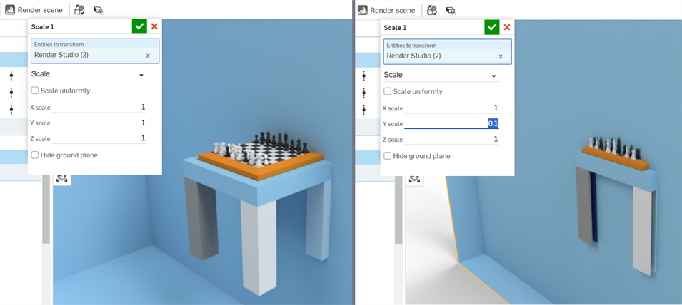
シーンリストのエンティティは、あるレイヤーから別のレイヤーに移動することはできません (例: シーンリストの上下など)。アイテムが空間内のどこにあるかを決定する変換マトリックスは、エンティティとともに (エンティティインスタンスとして) 保存されます。これらの変換は、各エンティティに追加すると累積されます。最上位の要素を変換すると、下位レベルの要素もすべて平行移動し、1 つのグループとしてまとめて移動されます。
たとえば、シーンリストで最上位の Render Studio を選択し、トランスフォームツールを使用して Y 軸を 1 から 0.1 にスケールします。シーンのすべてのパーツが同時に縮小されます (下の 2 番目の図)。
パーツ、Part Studio、およびアセンブリのトランスフォームについて詳しくは、シーンリストのエンティティのトランスフォームを参照してください。
シーンリストのエンティティにカーソルを合わせると、カーソルを合わせたエンティティの背景が水色に変わります。グラフィック領域では要素は黄色のアウトラインで囲まれています (下の最初の図を参照)。
シーンリストのエンティティをクリックすると、クリックしたエンティティの背景が濃い青色に変わります。グラフィック領域の要素の上に黄色の塗りつぶしが表示されます (下の 2 番目の図を参照)。
下の画像で列車のコンテナの背面が選択されているように、エンティティが別のエンティティの後ろにあっても、アウトラインとフィルの両方が表示されます。
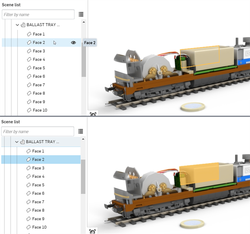
または、グラフィック領域でエンティティを直接選択します。
選択の動作は、トグルと同様です。一度クリックして選択し、もう一度クリックして選択を取り消します。また、[Ctrl] を押しながらクリックすることで、複数の項目を追加選択したり取り消すこともできます。
詳細は、選択を参照してください。
[名前で絞り込む] フィールドを使用して、シーンリストエンティティの名前でシーンリストを検索します。フィルタ切り替えボタン (![]() ) をクリックすると、シーンリストの内容を特別なフィルタコマンド (前にコロンが付きます) で絞り込めます。
) をクリックすると、シーンリストの内容を特別なフィルタコマンド (前にコロンが付きます) で絞り込めます。
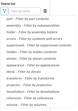
-
:part - パーツごとに絞り込み、オプションで名前別に絞り込みます
-
:assembly - サブアセンブリごとに絞り込み、オプションで名前別に絞り込みます
-
:folder - アセンブリフォルダ別に絞り込みます
-
:errors - エラーのあるコンテンツを絞り込みます
-
:suppressed - 抑制されたコンテンツを絞り込みます
-
:hidden - 非表示のコンテンツを絞り込みます
-
:shown - 表示されたコンテンツを絞り込みます
-
:appearance - 外観で絞り込みます
-
:decal - デカールで絞り込みます
-
:transform - トランスフォームで絞り込みます (移動、回転、スケール)
-
:projector - プロジェクターで絞り込みます
-
:tessellation - テッセレーションで絞り込みます
-
:reference - 参照で絞り込みます
-
:volume - ボリュームで絞り込みます
フィルターを組み合わせると、次のようなより詳細な結果が得られます。
-
:assembly: errors: は、エラーのあるすべてのアセンブリを検索します。オプションでアセンブリ名も指定できます
-
:part :hidden は、非表示になっているすべてのパーツを検索します。必要に応じて、パーツ名を含めて絞り込みます。
フィルターフィールドにフィルターまたは名前を入力すると、フィルターアイコン (![]() ) が青色に変わり、フィルターが使用されていることを示します。フィルターをクリアするには、フィルターフィールドの右側にあるクリア (
) が青色に変わり、フィルターが使用されていることを示します。フィルターをクリアするには、フィルターフィールドの右側にあるクリア (![]() ) アイコンを使用します。
) アイコンを使用します。
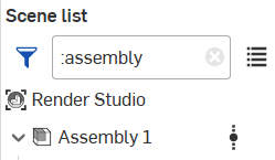
リストからフィルターコマンドを選択すると、フィルターフィールド内の既存のフィルターがすべて削除または置換されます。
フィルターフィールドにフィルター (:errors など) を入力すると、リストからフィルターを選択した場合と同じ結果になります。
| アイコン | 説明 |
|
|
最上位の Render Studio シーン |
|
|
Part Studio |
|
|
構成済み Part Studio |
|
|
アセンブリまたはサブアセンブリ |
|
|
構成済みアセンブリまたはサブアセンブリ |
|
|
パーツ |
|
|
構成済みパーツ |
|
|
サーフェスまたは面 (メッシュ) |
|
|
アセンブリフォルダ |
|
|
プロジェクタ |


|
参照の更新を示します。参照を更新するアイコンとその意味の完全なリストについては、参照を更新するを参照してください。 |
|
|
自動以外のテッセレーション値が適用されていることを示します。 |
|
|
シーンリストのエンティティを表示/非表示にします。 |
|
|
トランスフォーム (平行移動) |
|
|
トランスフォーム (回転) |
|
|
トランスフォーム (スケール) |
|
|
外観 |
|
|
リンクされた外観 |
|
|
デカール |
|
|
リンクデカール |
|
|
ボリューム (Render Studio Advanced のみ)。ボリュームの作成を参照してください。 |
シーンリスト内のコンポーネント:
-
フィルターフィールド - シーンリスト内のアイテムを絞り込みます。これは、パーツ、Part Studio、またはアセンブリを多く含むシーンに便利です。面は絞り込めません。高度なフィルタリングオプションについては、シーンリストを絞り込むを参照してください。
-
検索結果をリストとして表示 (
 ) - 検索結果を階層ではなくフラットリストとして表示します。
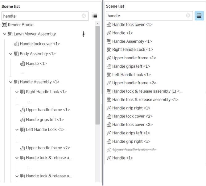
シーンリスト結果の既定の階層ビュー (左) とリストビュー (右)
-
Render Studio - 現在のシーンのルートディレクトリ。その他すべてのシーンノードは、挿入されたパーツ、Part Studio、アセンブリ、プロジェクターなどは Render Studio の下に一覧表示されます。
-
Part Studio/アセンブリ親グループ - シーンが作成されると、パーツ、Part Studio、またはアセンブリがシーンに挿入されます。これらは、これらのパーツ、Part Studio、またはアセンブリに含まれるすべてのパーツや面の最上位のグループです。
Part Studio またはアセンブリの親グループの下にあるエンティティは次のとおりです。
-
サブアセンブリ - 親アセンブリ内のアセンブリ。サブアセンブリには、パーツ、サーフェス、および面が含まれます。
-
パーツ - 複数の面を持つ単一の閉じたソリッドボディ。パーツは、Part Studio/アセンブリの親グループインスタンスの下の第 1 レベルです。
-
サーフェス - 1 つまたは複数の面を持つことはできるが、体積を持たないエンティティで、パーツから独立しています。サーフェスは、Part Studio / アセンブリの親グループの下の第 1 レベルです。
-
面 (メッシュ) - 領域を持ち、エッジで囲まれたパーツまたはサーフェス領域の一部。たとえば、長方形のパーツには 6 つの面があります。面は、必ずしも球体などのエッジで囲まれている必要はありません。パーツ名の左にある矢印をクリックすると、その下の面が展開されます。
-
フォルダ - アセンブリを Render Studio に挿入すると、すべてのフォルダとフォルダ構造が維持されます。フォルダは、他のシーンリストコンポーネントと同じように表示、非表示、分離、抑制ができます。
Render Studio では、フォルダの順序は変更・移動できません。ただし、アセンブリで順序を変更したり、新しいバージョンを作成したり、Render Studio でリファレンスを更新したりすることはできます。詳細は、Render Studio シーンエンティティを更新するを参照してください。
-
-
トランスフォーム - ツールバーのトランスフォームツールを使用してシーンで実行されるすべてのトランスフォーム (平行移動、回転、スケール) のリストを表示します。シーンリストのエンティティのトランスフォームを参照してください。
-
外観 - シーン内のインポート (リンク) および適用されたすべてのパーツ/面の外観のリストを表示します。外観を 1 つ選択すると、そのパラメータは外観パネルで編集できます。複数の外観を選択した場合、それらは外観パネルにリストとして表示されます。詳細は、複数の外観の選択を参照してください。
-
プロジェクター - シーン内のすべてのプロジェクターのリストを表示します。プロジェクターは、シーン内のあらゆるエンティティ、さらにシーン全体に影響を与えることができます。投影は、外観テクスチャマッピングをシーンの面やパーツに投影したときに、どのようにトランスフォーム、回転、スケールするかを決定します。
-
ボリューム (Render Studio Advanced のみ) - シーン内のすべてのボリュームのリストを表示します。ボリュームとは、外観の体積部分が存在し、レンダリングされる立方体領域です。ボリュームはオプションで OpenVDB の 3D テクスチャにすることができます。Advanced 以外のユーザーは、ボリュームを含むシーンを開くことができますが、そのプロパティは編集できません。
外観を外観リストからドラッグして、シーンリスト内のエンティティ (Render Studio、Part Studio、アセンブリ、パーツ、または面) に直接ドロップできます。これにより、シーンリスト内から直接外観を簡単に割り当てることができます。シーンリストエンティティに外観を追加するを参照してください。
外観にカーソルを合わせると、そのサムネイルが右に表示されます。これにより、外観リストから直接外観をプレビューできます。

シーンリストエンティティ (Render Studio、Part Studio、アセンブリ、アセンブリフォルダ、パーツ、または面) を右クリックすると、次のコンテキストメニューオプションが表示されます。
すべてのオプションがすべてのシーンリストエンティティで使用できるわけではありません。オプションは、どのシーンリストエンティティを右クリックしたかによって異なります。
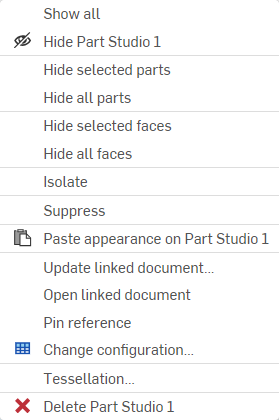
-
すべて表示 - シーンリストのすべてのアイテムを表示します。
-
非表示 (
 )/表示 (
 ) - このオプションは、トランスフォーム、外観、およびプロジェクタを除くすべてのシーンリストアイテムで使用できます。このオプションは、シーン内のパーツまたはインスタンスの表示/非表示を切り替えます。たとえば、パーツを選択すると、その名前の右に目のアイコンが表示されます。このアイコンをクリックすると、シーン内のパーツの可視性が非表示になります。アイコンをもう一度クリックすると、そのパーツが表示されます。
 -
すべてのパーツを非表示 - 現在の選択範囲とその下にあるすべてのパーツを非表示にします。
-
すべての面を非表示 - 現在選択されている面とその下のすべての面を非表示にします。
-
分離 - 1 つまたは複数のパーツ、Part Studio、またはアセンブリが選択されている場合にのみ、シーンリストのコンテキストメニューから使用できます (Render Studio または面エンティティでは使用できません)。[分離] を選択すると、選択したすべてのエンティティが表示可能になり、他のすべてのエンティティはグラフィック領域で非表示になります。
グラフィック領域の上部中央に、分離モードであることを示すバナーが表示されます。[完了] をクリックしてこのモードを終了します。
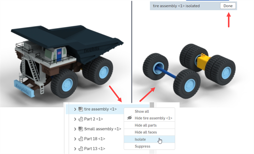
[分離] は、それぞれのコンテキストメニューからトランスフォームとプロジェクタに適用することもできます。詳細は、トランスフォームのコンテキストメニューとプロジェクタのコンテキストメニューを参照してください。
-
抑制/抑制解除 - シーンから 1 つまたは複数のエンティティを非表示にします。抑制すると、エンティティはグラフィック領域に表示されません。面以外のすべてのエンティティを抑制できます。子を持つエンティティを抑制すると、すべての子が抑制されます。
エンティティを非表示にすると、その名前は斜体になり、フォントは淡色表示になり、テキストには取り消し線が付きます。右クリックして [抑制解除] を選択すると、エンティティがアクティブな状態に戻ります。
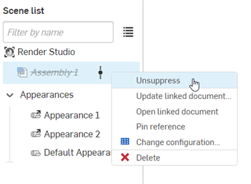
抑制しても、関連するシーンリストの外観、トランスフォーム、投影はシーンリストから削除されません。ただし、グラフィック領域には表示されません。
-
外観を貼り付け - 外観ライブラリ、外観リスト、またはグラフィック領域から外観をコピーした場合、このオプションを使用して現在選択されているシーンリストのエンティティに貼り付けます。外観のコピーと貼り付けを参照してください。
-
外観の割り当て解除 - 選択したエンティティから外観を削除します。
-
リンク先: Part Studio の外観 - Part Studio のマテリアル/外観が割り当てられているパーツがシーンに挿入され、この外観が割り当てられていない場合、このオプションは元の Part Studio の外観をそのパーツに再リンクします。
パーツと面は両方とも (個別に、または複数) 選択して、元の Part Studio の外観に再度リンクできます。
パーツのコンテキストメニューにオプションを表示するには、パーツの割り当てを完全に解除する必要があります。パーツに割り当てられた面と割り当てられていない面が混在している場合、パーツのコンテキストメニューにオプションを表示するには、面を選択する必要があります。
このオプションを面に使用する場合、2 つのシナリオがあります。この例では、Render Studio の外観がパーツに割り当てられ、別の Render Studio の外観が面に割り当てられています。
-
パーツの面に Part Studio の外観が割り当てられていない場合は、面を右クリックして [Part Studio の外観にリンク] を選択すると、パーツの Part Studio の外観ではなく、パーツの Render Studio の外観にリンクされます。
-
パーツの面に Part Studio の外観が割り当てられている場合は、面を右クリックして [Part Studio の外観にリンク] を選択すると、Part Studio (面) の外観にリンクされます。
詳細は、Part Studio マテリアルから Render Studio の外観へのマッピングを参照してください。
-
-
リンクされたドキュメントを更新 - 参照マネージャーダイアログが開き、最新バージョンに更新したり、ドキュメントバージョンを選択的に更新したりできます。詳細は、リンクされたシーンエンティティを更新するを参照してください。
-
リンクされたドキュメントを開く - リンクされたドキュメント (Part Studio またはアセンブリ) を新しいブラウザタブで開きます。
-
参照のピン留め/ピン留めを解除 - ピン留めすると、インスタンスはブランチの最新バージョンにリンクされ、ピン留めされます。
-
分解ビュー - インポートしたアセンブリに 1 つまたは複数の分解ビューがある場合、このオプションを使用してダイアログを開き、アセンブリに関連する分解ビューを選択できます。これで、選択した分解ビューがグラフィック領域に表示されます。アセンブリの分解ビューへのアクセスを参照してください。
-
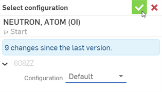
コンフィギュレーションを変更 - コンフィギュレーションを選択ダイアログが開き、Part Studio またはアセンブリ用に別のコンフィギュレーションを選択できます。コンフィギュレーションを含む Part Studio またはアセンブリの挿入を参照してください。
-
すべてのテッセレーションをリセット - 最上位の Render Studio エンティティを右クリックして表示されるコンテキストメニューのみで使用できます。以下のすべてのエンティティのカスタムテッセレーション設定を自動にリセットするメッセージプロンプトが表示されます。[リセット] ボタンをクリックしてすべてのテッセレーションをリセットするか、[キャンセル] をクリックして変更を加えずにメッセージプロンプトを閉じます。

-
一致するインスタンスを選択 - 挿入したアセンブリの配下のパーツまたはサブアセンブリアセンブリのみから使用できます。これを選択すると、パーツまたはサブアセンブリの一致するインスタンスがすべて選択されます。1 つの用途はパターン化されたパーツで、このオプションではパターン化されたすべてのパーツインスタンスが選択されます。
-
テッセレーション - テッセレーションダイアログが開き、現在選択されているシーンリストエンティティ (Render Studio、Part Studio、アセンブリ、またはパーツ) に対して、[自動]、[粗い]、[標準]、[細かい]、または [カスタム] から別のテッセレーション値を選択できます。[カスタム] を選択すると、追加のオプションを使用できます。

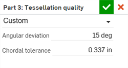
テッセレーション設定は、明示的な設定がない以下のすべてのエンティティに適用されます。たとえば、アセンブリにテッセレーション設定の [細かい] を適用すると、アセンブリの下にある、明示的な設定がないすべてのエンティティに同じ設定が適用されます。
[自動] 以外のテッセレーション値が適用されている場合、シーンリストの要素の横にテッセレーションアイコンが表示されます。
-
角度偏差 - テッセレーション中に曲面を分割するセグメントの数を制御します。たとえば、10 度の値を指定すると、36 の平面上の面をもつ円柱になります。
-
弦の許容差 - テッセレーションされたジオメトリが基本サーフェスから変化することが許可される最大距離。
-
-
削除 - 選択した 1 つまたは複数の最上位のパーツ、Part Studio、またはアセンブリを削除します。Part Studio/アセンブリの下にある面やパーツは削除できません。
シーンリスト内の非表示のエンティティは、ページをリロードしたりログアウトした後は持続しません。非表示になっているエンティティは、ページがリロードされた後、またはログインし直した後に表示されます。
トランスフォームコンテキストメニュー
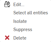
シーンリストトランスフォームでトランスフォームのサムネイルを右クリックすると、次のオプションを含むコンテキストメニューが表示されます。
-
編集 - 現在のトランスフォームを追加で編集できるトランスフォームダイアログを開きます。
-
すべてのエンティティを選択 - トランスフォーム操作の一部であったすべてのパーツを選択します。
-
分離 - 選択すると、選択したトランスフォームを含むすべてのエンティティが表示され、その他すべてのエンティティはグラフィック領域で非表示になります。
グラフィック領域の上部中央に、分離モードであることを示すバナーが表示されます。[完了] をクリックしてこのモードを終了します。
-
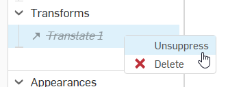
抑制/抑制解除 - 抑制は、現在選択されているトランスフォームがシーンに与える効果を削除します。
トランスフォームを非表示にすると、名前は斜体になり、フォントはグレー表示され、テキストには取り消し線が付きます。右クリックして [抑制解除] を選択すると、トランスフォームがシーンに再適用されます。
-
削除 - パーツの状態をトランスフォーム前の元の位置に戻し、シーンリストから現在のトランスフォームを削除します。
誤って削除してしまった場合でも、ツールバーの元に戻す (![]() ) オプションを使用してトランスフォームを復元できます。
) オプションを使用してトランスフォームを復元できます。
外観のコンテキストメニュー
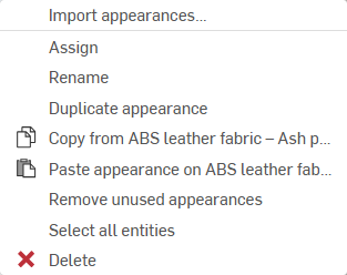
シーンリストの外観で外観のサムネイルを右クリックすると、次のオプションを含むコンテキストメニューが表示されます。
-
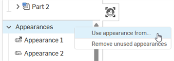
外観を使用... - 現在のドキュメントまたは他のドキュメントから Render Studio タブを選択して、適用された外観を現在の Render Studio タブに表示できます。詳細は、Render Studio の別のタブにある外観を使用するを参照してください。
-
割り当て - パーツに外観を割り当て、シーンリストの下位にある属性をすべてクリアします。
-
名前を変更 - 現在の外観の名前を変更します。
-
外観のリンク解除 - 元は Part Studio のパーツに割り当てられていて、パーツが新しいシーンに取り込まれたときに Render Studio の外観にマップされていたマテリアルのリンクを解除します。Part Studio のマテリアルから Render Studio の外観へのマッピングを参照してください。
-
外観の複製 - 現在の外観とそのすべてのパラメータを複製します。コピーは、現在選択されている外観のすぐ下の外観リストに配置されます。
-
[外観] (
 ) からコピー - シーンリストで現在選択されている外観をクリップボードにコピーします。
 -
外観を [外観] に貼り付け (
 ) - クリップボードの外観 (ソース外観) から、シーンリストで現在選択されている外観 (ターゲット外観) に貼り付けます。ソースの外観がターゲットの外観に置き換わります。
ターゲットの外観の名前を事前に変更していない場合は、ソースの外観名が使用されます。ターゲットの外観の名前を事前に変更した場合は、ソースの外観がターゲットの外観に置き換わっても、この名前は保持されます。
-
未使用の外観を削除 - シーンで使用されていない外観がリストにある場合、このオプションはすべての外観を外観リストから削除します。これは、未使用の外観が多数ある長いリストを整理するのに役立ちます。未使用の外観がない場合は、何も削除されなかったことを知らせる青色の情報メッセージが表示されます。
-
すべてのエンティティを選択 - シーン内でこの外観が適用されているすべてのパーツまたは面を選択します。
-
削除 - 選択した 1 つまたは複数の外観が未使用の場合に、外観リストから削除します。使用中の外観は削除できません。
リンクされている外観の名前は変更できません。
プロジェクタのコンテキストメニュー
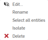
シーンリストプロジェクターでプロジェクターのサムネイルを右クリックすると、次のオプションを含むコンテキストメニューが表示されます。
-
編集 - 現在のプロジェクターを追加で編集できるプロジェクターダイアログを開きます。
-
名前を変更 - 現在のプロジェクターの名前を変更します。
-
すべてのエンティティを選択 - シーン内でこのプロジェクタが適用されるすべてのエンティティとパーツを選択します。
-
分離 - 選択すると、選択したプロジェクタを含むすべてのエンティティが表示され、その他すべてのエンティティはグラフィック領域で非表示になります。
グラフィック領域の上部中央に、分離モードであることを示すバナーが表示されます。[完了] をクリックしてこのモードを終了します。
-
削除 - プロジェクタを削除し、シーン内の関連するエンティティとパーツへの影響を削除します。
誤って削除してしまった場合でも、ツールバーの元に戻す (![]() ) オプションを使用してプロジェクターを復元できます。
) オプションを使用してプロジェクターを復元できます。
ボリュームのコンテキストメニュー (Render Studio Advanced のみ)
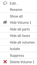
シーンリストでボリュームのサムネイルを右クリックすると、次のオプションを含むコンテキストメニューが表示されます。
-
編集 - 現在のボリュームを追加で編集できるボリュームダイアログを開きます。
-
名前を変更 - 現在のボリュームの名前を変更します。
-
すべて表示 - シーンリストのすべてのアイテムを表示します。
-
非表示 (
 )/表示 (
 ) - シーン内のボリュームの表示/非表示を切り替えます。
 -
すべてのパーツを非表示 - 現在の選択範囲とその下にあるすべてのパーツを非表示にします。
-
すべての面を非表示 - 現在選択されている面とその下のすべての面を非表示にします。
-
Hide all volumes - Hides all volumes from the current selection and below.
-
分離 - 選択すると、現在のボリュームが表示され、その他のすべてのエンティティはグラフィック領域で非表示になります。
グラフィック領域の上部中央に、分離モードであることを示すバナーが表示されます。[完了] をクリックしてこのモードを終了します。
-
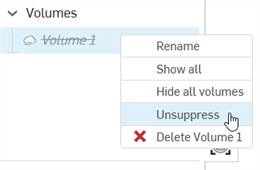
抑制/抑制解除 - 抑制は、現在選択されているボリュームがシーンに与える効果を削除します。
ボリュームを非表示にすると、名前は斜体になり、フォントはグレー表示され、テキストには取り消し線が付きます。右クリックして [抑制解除] を選択すると、ボリュームがシーンに再適用されます。
-
削除 - ボリュームを削除し、シーン内の関連するエンティティとパーツへの影響を削除します。
-
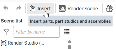
パーツ、Part Studio、またはアセンブリを Render Studio シーンに挿入するには、次の手順を実行します。
-
ツールバーの挿入ボタン (
 ) をクリックします。
-
[パーツ、Part Studio、またはアセンブリの選択] ダイアログが開きます。
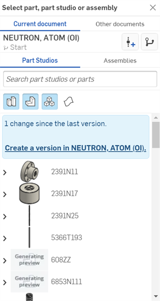
Render Studio シーンは、エンティティが最初にシーンにインポートされた時点のドキュメントのスナップショット (バージョン) と考えることができます。このため、エンティティをインポートする前にバージョンが必要です。[<ドキュメント名> でバージョンを作成する] リンクをクリックし、[バージョンを作成] ダイアログに情報を入力して、[作成] ボタンをクリックします。これが完了すると、すべてのドキュメントアセットが使用可能になり、選択ダイアログから任意のパーツ、Part Studio、またはアセンブリをインポートできるようになります。
エンティティを Render Studio タブにインポートすると、新しいバージョンが作成されない限り、この Render Studio タブ以外のドキュメントで作成された (またはインポートされた) データには、この Render Studio シーンからアクセスできなくなります。また、ドキュメントパネルの [バージョンを作成] ボタン (
 ) をクリックして [バージョンを作成] ダイアログを開けば、ドキュメントのバージョンをいつでも作成できます。詳細は、バージョンと履歴を参照してください。
 -
クリックしてシーンに挿入したいエンティティを選択します。これには、現在のドキュメントまたは他のドキュメントのパーツ、複合部品、サーフェス、Part Studio、またはアセンブリを使用できます。
[パーツを選択] ダイアログ、[Part Studio] ダイアログ、または [アセンブリ] ダイアログにアクセスするたびに、シーンに挿入できるエンティティは 1 つだけです。ただし、同じシーンには要素をいくつでも挿入できます。
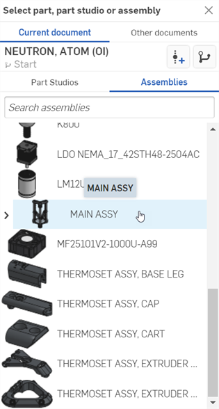
挿入ダイアログ (パーツ、Part Studio、またはアセンブリの選択) について詳しくは、パーツとアセンブリを挿入するを参照してください。
ねじ山は、ジオメトリに影響を与えないねじを視覚的に表現したものです。Onshape は、外部のねじとタップ穴のねじ山を Part Studio に表示します。これにより、ねじの形状を再計算する必要がなくなるため、反復と再生が速くなります。詳しくは、穴および外部ねじを参照してください。
ねじ山のある穴や外部ねじを持つパーツをシーンに挿入すると、Part Studio と同じように表示されます。
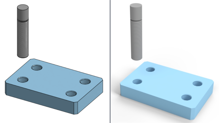
Part Studio (左) と Render Studio (右) に表示されているねじ山
パーツに外観を適用したら、次のねじ山をインプレースでレンダリングできます。
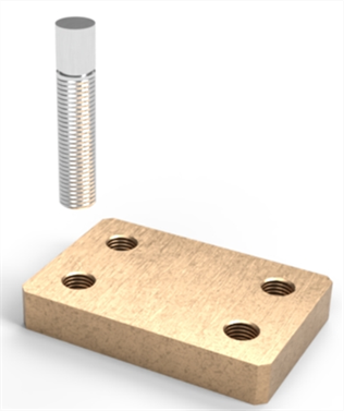
Render Studio シーンではねじ山を削除できません。Part Studio でのみ調整できます。
Render Studio のシーンで使用されているエンティティが Render Studio タブの外部で更新された場合、シーンエンティティの横に更新リンクアイコン (![]() ) が表示されます。これは、参照エンティティを更新する必要があることを示しています。
) が表示されます。これは、参照エンティティを更新する必要があることを示しています。
更新されたエンティティが現在のワークスペースにある場合は、新しいバージョンや更新は不要で、新しいエンティティをすぐに利用できます。新しいバージョンや更新は、現在のワークスペースの外部で更新されたエンティティにのみ必要です。
シーンエンティティを更新するには、次の手順に従います。
-
ドキュメントの新しいバージョンがある場合は、シーンリストエンティティの横に参照を更新するアイコンが表示されます。

-
エンティティを右クリックし、コンテキストメニューから [リンクされたドキュメントを更新] を選択します。
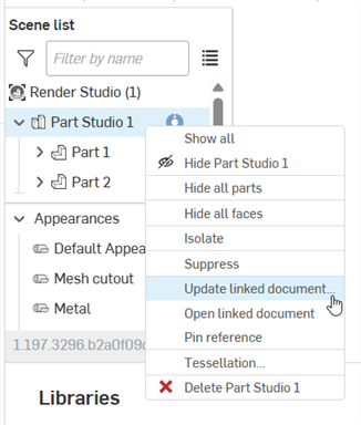
-
[参照マネージャー] ダイアログが開きます。更新するエンティティを確認して、[選択項目を更新] ボタンをクリックします。
![[参照マネージャー] ダイアログ](Resources/Images/render-studio/update-linked-03.png)
-
Render Studio タブは、更新されたバージョンが適用された状態でブラウザにリロードされます。
-
右上隅の [x] をクリックしてダイアログを閉じます。
アセンブリに 1 つまたは複数の分解ビューがある場合、シーンに挿入すると、これらの分解ビューのいずれかにアクセスしてグラフィック領域に表示できます。
-
シーンリストでアセンブリを右クリックし、[分解ビュー] を選択します。

-
[分解ビュー] ダイアログが開きます。

-
[既定] ドロップダウンをクリックして、目的の分解ビューを選択します。このリストには複数の分解ビューが含まれている場合があることに注意してください。
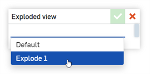
-
チェックマーク (
 ) をクリックして新しいビューを確定します。
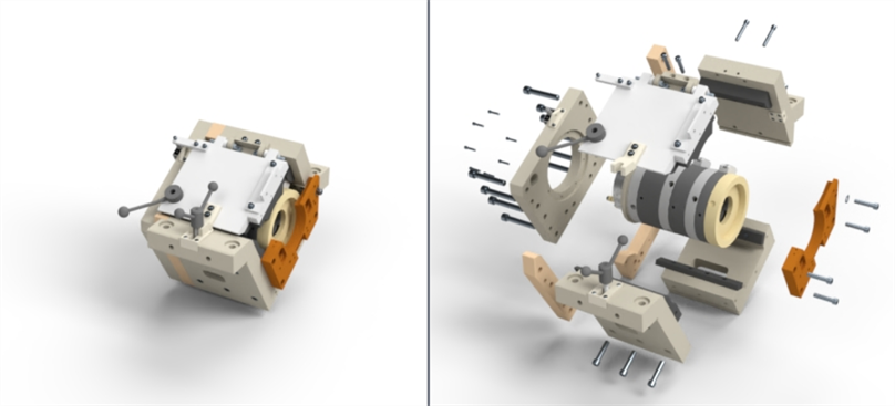
既定 (分解されていない) ビュー (左) と分解ビュー (右)
ダイアログにもう一度アクセスしてドロップダウンから [既定] を選択し、チェックマーク (![]() ) をもう一度クリックすると、いつでも他の分解ビューに切り替えたり、既定 (分解されていないビュー) に戻したりできます。
) をもう一度クリックすると、いつでも他の分解ビューに切り替えたり、既定 (分解されていないビュー) に戻したりできます。
-
ツールバーの挿入ボタン (
 ) をクリックします。
-
[パーツ、Part Studio、またはアセンブリの選択] ダイアログが開きます。

-
追加のコンフィギュレーションを含む Part Studio またはアセンブリを探します (下の最初の図を参照)。ドロップダウンをクリックして、必要なコンフィギュレーション を選択します (下の 2 番目の図を参照)。
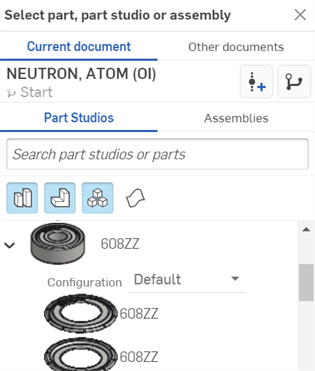
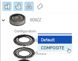
-
構成済みの Part Studio またはアセンブリをクリックしてシーンに挿入します。
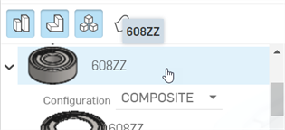
-
シーンに挿入した後で Part Studio またはアセンブリに別のコンフィギュレーションを選択するには、シーンリストで Part Studio またはアセンブリを右クリックし、コンテキストメニューから [コンフィギュレーションを変更] を選択します。
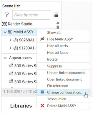
-
[コンフィギュレーションを選択] ダイアログが開きます。
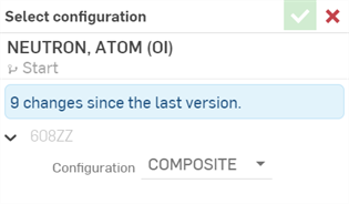
-
ドロップダウンをクリックして新しい構成を選択し、チェックマーク (
 ) を押して新しいコンフィギュレーションを確定し、シーン内の Part Studio またはアセンブリを更新します。
1 つまたは複数のシーンリストエンティティをトランスフォームするには、次の手順を実行します。
-
ツールバーのトランスフォームボタン (
 ) をクリックします。
 -
これにより、次のダイアログが開き、エンティティの平行移動、回転、およびスケールを変更できます。
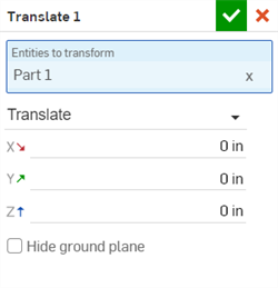
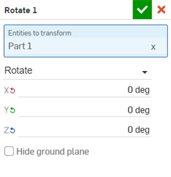
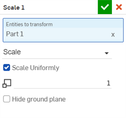
-
Entities to transform - Select all entities you would like transformed. This includes the top level Render Studio, Part Studios, Assemblies, parts, and volumes (Render Studio Advanced only). Faces cannot be transformed.
どのトランスフォームも、対象のすべてのエンティティの中心が原点となります。たとえば、1 つのパーツを選択した場合、そのパーツの中心が原点として使用されます。2 つのパーツを使用する場合、両方のパーツを組み合わせた中心が原点として使用されます。
境界ボックスが表示され、原点とトランスフォームの選択に含まれるすべてのエンティティが表示されます。
-
トランスフォームドロップダウン - [平行移動]、[回転]、または [スケール] を選択します。トランスフォームダイアログごとに実行できるトランスフォーム操作は 1 つだけですが、同じシーンに複数のトランスフォームを適用できます。すべてのトランスフォームはシーンリストにあります。トランスフォームオプションは以下のとおりです。
-
平行移動 - シーンの原点を基準に、選択範囲を X、Y、Z 軸に沿って移動します。測定単位はメートルで、負または正の数です。
-
回転 - シーンの原点を基準に、選択範囲を X、Y、Z 軸に沿って回転させます。測定単位は度単位で、-360 度から +360 度の範囲です。
-
スケール - 選択対象の中心点を基準に、x、y、z 軸に沿って選択対象を拡大 (大きく) または縮小 (小さく) します。測定値は選択対象の元のサイズに基づきます。たとえば、スケール 1.000 x 1.000 y は、スケールがパーツの元のサイズの 100% であることを意味します。0.001 から 1 までの端数を設定すると、選択対象のサイズが縮小されます。スケール軸を 0 に設定することはできません。
-
均一にスケーリング - スケール変換を選択した場合、このチェックボックスを有効にしておくと、入力した値だけエンティティとパーツを均等にスケーリングできます。チェックボックスをオフにすると、X、Y、Z 軸に沿って個別にスケーリングされます。
-
-
-
グラウンド平面を非表示 - 環境の仮想地表平面を非表示にします。地表の設定について詳しくは、環境パネルを参照してください。
または、[トランスフォーム] ダイアログに入力する前に、シーンリストまたはグラフィック領域からエンティティを事前に選択することもできます。ツールバーの [トランスフォーム] ボタン (
 ) をクリックすると、選択したエンティティが [トランスフォームするエンティティ] フィールドに自動的に入力されます。
 -
-
トランスフォームツールを使用するときに、ダイアログで [平行移動] または [回転] を選択した場合は、グラフィック領域でマニピュレータを調整します。

平行移動マニピュレータ (左)、回転マニピュレータ (右)
尺度変換はダイアログに数値で入力されます。グラフィック領域には関連するマニピュレータはありません。
-
完了したら、チェックマーク (
 ) をクリックして新しいトランスフォームを確定します。
複数のトランスフォームは、作成されてシーングラフにリストされている順序で適用されます。
アセンブリ内のエンティティが変換され、そのアセンブリが Render Studio で更新されると、Render Studio のトランスフォームは新しいアセンブリトランスフォーム上で再度適用されます。このように、Render Studio のトランスフォームは非破壊的です。
各トランスフォームについて、すべてのトランスフォームエンティティを編集、選択、分離、抑制、削除できます。詳細は、トランスフォームコンテキストメニューを参照してください。
シーンリストのすべてのエンティティまたはエンティティのグループ (Render Studio 全体、Part Studio、アセンブリ、パーツ、面) には、独自のプロジェクタを関連付けることができます。プロジェクタはエンティティに適用される外観/テクスチャに影響しますが、エンティティ自体には影響しません。
プロジェクターをエンティティに関連付けるには、次の手順を実行します。
-
ツールバーのプロジェクターアイコン (
 ) をクリックします。
-
[プロジェクター] ダイアログが開きます。ダイアログに次の情報を入力します。
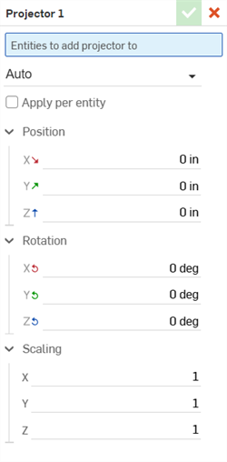
-
名前 [プロジェクター 1] - プロジェクターの名前を入力します
-
プロジェクタを追加するエンティティ - このプロジェクタの影響を受けるすべてのエンティティ。ダイアログが開いている状態で、シーンリストまたはグラフィック領域からシーンリストエンティティを選択します。これには、Render Studio、Part Studio、アセンブリ、パーツ、および面全体が含まれ、プロジェクタの影響に追加されます。
-
投影タイプ- - [自動]、[平面]、[キュービック]、[円筒状]、[球状]、または [サーフェス] を選択します。
-
正規化 (円筒状または球状の投影タイプでのみ使用可能) - 円柱や球体のサイズに関係なく、投影の水平軸を中心に 1 回回転してテクスチャが 2 回繰り返されることを確認します。
-
制限 (円筒投影タイプでのみ使用可能) - チェックボックスをオンにすると、円筒状投影の上部と下部に平面投影が追加されます。
-
エンティティごとに適用 - チェックボックスをオンにすると、選択したエンティティのトランスフォームがエンティティとともに移動します。
-
位置 (X/Y/Z) - X、Y、Z 軸に沿った長さ測定の位置のトランスフォームを入力します。
-
回転 (X/Y/Z) - X、Y、Z 軸に沿った回転のトランスフォームを度単位で入力します。
-
スケーリング (X/Y/Z) - X、Y、Z 軸に沿ってスカラー変換を比率値 (1 は元のスケール) で入力します。
または、プロジェクタダイアログを開く前に、シーンリストまたはグラフィック領域からエンティティを事前に選択することもできます。ツールバーの [プロジェクタ] ボタン (
 ) をクリックすると、選択したエンティティが [プロジェクタに追加するエンティティ] フィールドに自動的に入力されます。
 -
-
プロジェクタトランスフォームツールを使用して、プロジェクタの位置、回転、拡大縮小を調整します。または、ダイアログに数値を入力してプロジェクタのトランスフォームを行ってください。
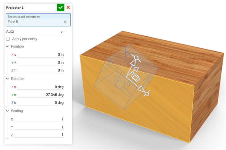
モデルの [面 5] に適用されているプロジェクタのトランスフォームを行います。
-
プロジェクタのトランスフォームツールは、選択したプロジェクションタイプによって変わります。
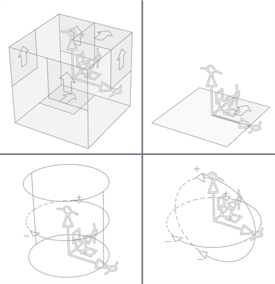
左上から時計回り: 自動/立方体、平面、球、円筒状のトランスフォームツール
-
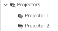
プロジェクタは選択したエンティティとパーツに関連付けられ、シーンリストの一番下の [プロジェクタ] ドロップダウンにあります。
現在のドキュメントまたは他のドキュメントの Render Studio タブのエンティティに適用されている外観を、現在の Render Studio タブで使用します。
Render Studio タブで、外観を以下のように表示させたいとします。
-
外観リストまたは外観リスト内の外観を右クリックし、コンテキストメニューから [外観を使用...] を選択します。
-
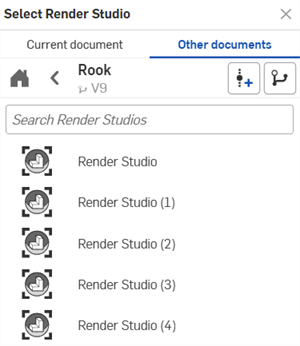
Render Studio を選択ダイアログが開きます。[現在のドキュメント] または [他のドキュメント] から [Render Studio] タブを選択します。
-
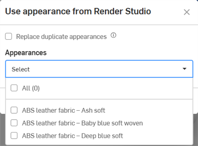
[外観を使用] ダイアログが開きます。次のオプションから選択します。
-
重複した外観を置き換える - これをオンにすると、現在の Render Studio タブの外観が、選択した Render Studio タブの外観とまったく同じ名前の場合、現在の Render Studio タブの外観が、選択した Render Studio タブの外観で上書きされます。これにより、以前の外観が割り当てられていたすべてのパーツ/インスタンスに、選択した Render Studio タブの外観が割り当てられます。
このオプションをオフにすると、選択した Render Studio タブから読み込まれた同じ名前の外観には、一意となるように名前の末尾に連番が追加されます。
- 外観 (選択ドロップダウン) - すべての外観を現在の Render Studio に取り込む場合は、[すべて] をオンにします。または、個々の外観をオンにして現在の Render Studio に取り込むこともできます。
-
-
このダイアログで選択したら、[適用] をクリックして、現在の Render Studio の外観リストに外観を表示します。または、[キャンセル] をクリックして、何も変更せずにダイアログを終了します。
外観は、現在の Render Studio タブの [外観] リストにアルファベット順に表示されます。
ヒント
-
お気に入りフォルダの外観とは異なり、選択した Render Studio タブのカスタム外観パラメータ設定は保持されます。
-
ユーザーアクセス権限を持たないリソースを使用している外観がある場合、その外観のチェックボックスは灰色になり、選択できません。
-
空の Render Studio タブを作成し、現在のドキュメントや他のドキュメントの Render Studio タブで頻繁に使用するすべての外観を格納する外観コンテナとして使用できます。
-
外観を使用ダイアログで、[すべて] をオンにしてからオフにすると、すべての外観が選択されたままになります。
Part Studio で作成したデカールは、それらを使用するパーツ、Part Studio、またはアセンブリを Render Studio に挿入する際に Render Studio にインポートされます。Part Studio でデカールフィーチャーを作成する方法については、デカールを参照してください。
パーツ、Part Studio、またはアセンブリを Render Studio に挿入すると、デカールは外観に変換され、シーンリストの外観リストに追加されます。
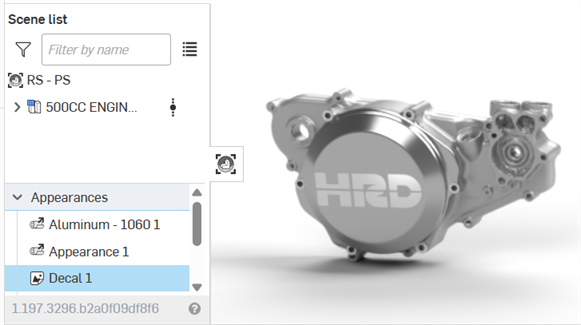
デカールアイコン (![]() ) に矢印が表示されているように、デカールは Part Studio フィーチャーにリンクされます。Part Studio でデカールを編集すると、ドキュメントのバージョンが作成され、Render Studio で参照が更新されたあとで、Render Studio に反映されます。
) に矢印が表示されているように、デカールは Part Studio フィーチャーにリンクされます。Part Studio でデカールを編集すると、ドキュメントのバージョンが作成され、Render Studio で参照が更新されたあとで、Render Studio に反映されます。
外観パネルでデカールのパラメータのいずれかを編集すると、リンクされていないデカール (![]() ) がリンクアイコンに表示されます。ただし、他の外観とは異なり、デカールの外観はソースの Part Studio で変更した場合、デカールの投影と UV 配置を引き続き追跡します。
) がリンクアイコンに表示されます。ただし、他の外観とは異なり、デカールの外観はソースの Part Studio で変更した場合、デカールの投影と UV 配置を引き続き追跡します。
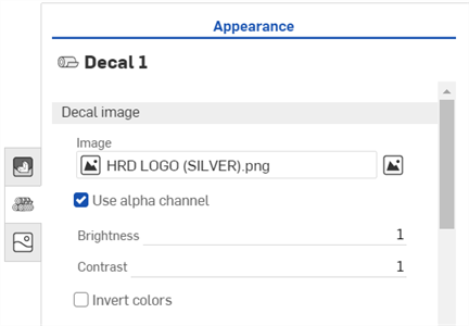
外観パネルにあるデカールの編集可能なパラメータは以下のとおりです。
-
デカール画像
-
画像 - デカールの画像ファイル。画像フィールドをクリックすると、画像を選択ダイアログが開きます。このダイアログでは、現在のドキュメントや他のドキュメントから画像を選択したり、コンピュータからインポートして現在の画像を置き換えたりできます。
-
アルファチャンネルを使用 - オンにすると、画像に透明なアルファチャンネルがある場合、そのチャンネルを使用してデカールをトリミングします。
-
明るさ - 画像の明るさを 0 ~ 1 のスケールで指定します。
-
コントラスト - 画像のコントラストを 0 ~ 1 のスケールで指定します。
-
色を反転 - 画像の色を反転させます。
-
-
デカールの外観
-
拡散粗さ - デカールの粗さの値。粗さの値が大きいほど、より粉っぽい外観になります。
-
メタリックな外観 - デカールの金属的な値。値が 1.0 の場合、反射は色付けされ、ビューの方向とは無関係になります。値が 0.0 の場合、反射は白く、方向に依存します。この場合、方向依存性は IOR (フレネル効果) に基づきます。
-
反射の粗さ - デカールの反射の粗さの値。粗さの値が大きいほど、ぼやけた反射になります。
-
反射の重み -反射量を制御します。
-
反射の異方性 - デカールの反射の異方性値。値が大きいほど強調表示が伸びます。
-
異方性回転 - 異方性の方向を変更します。値が 1 の場合、方向が 360 度回転します。
-
IOR - ボリューム内の屈折を決定します。また、メタリックでないデカールの反射率にも影響します。
-
バンプ - 外観ライブラリのバンプ機能のいずれかを介して、バンプマップまたは法線マップをデカールに添付します。
-
-
デカールトランスミッション
-
透過色 - ステンドグラスのように、デカールの厚さに関係なく透過するカラーエフェクト。
-
透過重量 - 拡散反射率と比較して、デカールを通過する光の量を重み付けします。
-
透過率の粗さ - 透過光の粗さの値。値を大きくすると、外観を通して見えるデカールはぼやけて見えます。
-
ヒント
-
他の外観とは異なり、デカールは外観ライブラリから選択できません。そのため、Render Studio 内のどのエンティティにも割り当てることはできません。これらはソース Part Studio からの外部参照としてのみ挿入できます。
-
デカールは複製や削除ができません。
-
デカールは非表示にできません。この問題に対応するには、デカールのトランスミッションの重みを 1 に設定します。デカールは透明になります。ただし、これはトランスミッションの色が白に設定されていて、デカールがマットの場合のみ有効です (光沢のある外観パラメータがない場合)。それ以外の場合は、面が正確に表示されない場合があります。
-
1 つの平面上の面に 3 つ以上のデカールを重ねて適用することはできません。また、円筒面には 3 つ以上のデカールを適用することはできません。その他のデカールは引き続き Render Studio に読み込まれますが、面には表示されません。
-
ソースの Part Studio でデカールを作成した順序によって、インポート時に Render Studio に適用される順序が決まります。
詳細は、Render Studio の例とリソースを参照してください。