 Sheet Metal Table and Flat View
![]()
Edit an existing sheet metal model’s bends, rips, and joints. View the sheet metal flat pattern.
The Sheet metal table and flat view is where you can edit an existing sheet metal model’s bends, rips, and joints, in addition to viewing the sheet metal flat pattern.
Click the Sheet metal table and flat view to open the panel. Select the sheet metal model to edit from the dropdown at the top of the panel. Click to select rows of the table; click again to deselect. Notice the cross-highlighting: what you select in the table is highlighted in the flat panel and in the model and vice versa. Selecting a rip or bend in the graphics area also selects (and scrolls to) the corresponding row in the table.
Right-click to access the Sheet metal context menu and commands: Move up/down in the table, Convert to rip/bend. To change a rip joint type, use the dropdown menu on the far right of the table row. Double-click a radii value to enter a new one.
You have the ability to sketch directly on a flat pattern for the purpose of making marks used in sheet metal manufacturing. Right-click on the sheet metal flat pattern and select New sketch. The sketch dialog opens with the preselected face of the sheet metal flat pattern as the sketch plane. Select a sketch tool and create a sketch as you normally would. When finished sketching, click the checkmark.
When exporting a sheet metal flat pattern, you have the option of including sketches with the export. When extruding on a flat pattern sketch, an abbreviated Extrude dialog box appears with options to add or remove material from the sheet metal. Click the checkmark to accept any changes.
Right-click on the flattened view of the sheet metal flat pattern to select the option to export as a DWG or DXF file.
Click the Sheet metal table and flat view icon to close the panel.
- With an existing sheet metal model in a Part Studio, click
 (midway along the right side of the window)
For example:
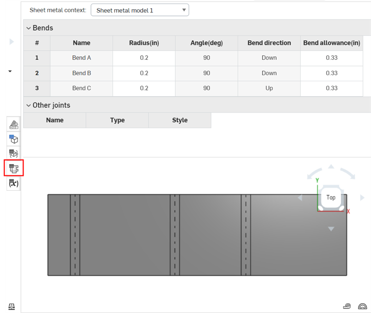
You can use the caret (next to the table title) to expand or collapse either table to make things easier to view
- Select the sheet metal model to edit from the dropdown at the top of the panel.
- Click to select rows of the table; click again to deselect.
- Notice the cross-highlighting: what you select in the table is highlighted in the flat panel and in the model and vice versa.
- You can multi-select rows (click to select, click again to deselect).
Selecting a rip or bend in the graphics area also selects (and scrolls to) the corresponding row in the table.
- Right-click to access the Sheet metal context menu and commands: Move up/down in the table, Convert to rip/bend.
- To change a rip joint type, use the dropdown menu on the far right of the table row.
Note that only 90° joints are able to be styled as Butt joints; non-90° joints must be Edge joints.
-
To directly edit the K Factor/Bend allowance/Bend deduction of a flat pattern bend, double-click in the column's cell and enter a custom value. Values outside an appropriate range highlight the cell red to indicate they are in error, and provide a tooltip to suggest a valid value range.
- Double-click a radii value to enter a new one.
Notes
-
As you make edits, the flat pattern updates as well as the sheet metal model in the graphics area. Features are created in the feature list, for example, a
 Modify joint feature is created when you convert a bend to a rip.
-
To reverse the orientation of the flat view, enable Flip direction up in the Sheet metal model feature dialog.
-
After a Corner break feature is applied, all model Joints' Type (Rip or Bend) and Style (Edge joint or Butt joint) are no longer editable in the Sheet metal table and flat view. It is recommended to add any Corner break features after finalizing all edits to the Sheet metal model's flanges and joints.
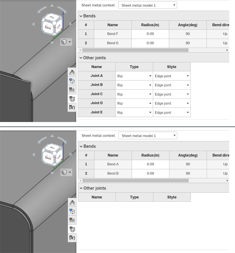
Before Corner break feature applied (top); after Corner break feature applied (bottom)
After converting a bend to a rip (using the table commands, explained above), a
![]() Modify joint feature is listed in the Feature list. You are able to right-click and Edit this new joint:
Modify joint feature is listed in the Feature list. You are able to right-click and Edit this new joint:
- Right-click the Modify joint feature in the Feature list, and select Edit, or double-click the Modify joint feature. The Modify joint feature dialog opens:
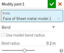
- Confirm the joint edge you want to modify (the Entity) or select a different one.
- Select one of the following joint types:
- Bend - Creates a curve between the faces/edges with a bend centerline and a radius. Keep the model properties default for the radius, or uncheck that box and specify a new bend radius.
- Rip - Create an association between the faces/edges where two sheet metal edges meet. When Rip is selected, select one of the following Rip edge types:
- Edge joint - Extends both edges to meet at their inner edges, The minimal gap from the Sheet metal model feature is used to create a gap between the two selections.
- Butt joint - Direction 1 - Extends the outer edges of the selected face/edge to each other until they meet. The minimal gap from the Sheet metal model feature is used to create a gap between the two selections. This option is only available for 90 degree joints.
- Butt joint - Direction 2 - Similar to Direction 1, but the handedness of the selected faces/edges is flipped.
- Tangent - Creates a tangent edge between the two selected faces/edges if one or more of those edges/faces are circular.
-
Click
 to accept changes.
The Modify joint feature appears in the Feature list, indicated by this icon
![]() .
.
You have the ability to sketch directly on a flat pattern for the purpose of making marks used in sheet metal manufacturing. Right-click on the sheet metal flat pattern:
- Select New sketch.
The sketch dialog opens with the preselected face of the sheet metal flat pattern as the sketch plane.
- Select a sketch tool and create a sketch as you normally would.
- When finished sketching, click the checkmark.
When exporting a sheet metal flat pattern, you have the option of including sketches with the export.
Extruding a flat pattern sketch
When extruding on a flat pattern sketch, an abbreviated Extrude dialog box appears with options to add or remove material from the sheet metal. Click the checkmark to accept any changes.
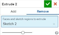
Currently, it is not possible to reuse Extrude features defined in the 3D model as Extrude features for the Sheet metal flat pattern. If you attempt to do so, the following warning opens:

Right-click on the flattened view of the sheet metal flat pattern to select the option to export as a DWG or DXF file:
- Right-click on the flat pattern, select Export DXF/DWG of flat pattern.
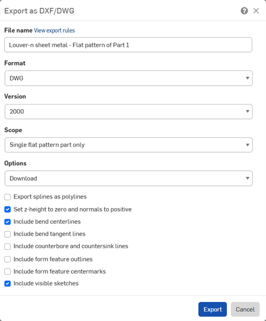
- If an export rule has been set up for exporting to DXF/DWG, a message appears (above in blue). To see the export rules, click View export rules. For more information about export rules, see Custom export rules.
- Specify a file name.
- Select a format, DWG or DXF.
- Select a version.
- Select a scope:
- Single flat pattern part only - Exports only this flat pattern part.
- All flat pattern parts in the current model - Exports the flat patterns of all parts created by that specific sheet metal model feature (i.e., multiple parts created by a single sheet metal model feature).
- All flat pattern parts in the Part Studio - Exports the flat patterns of all sheet metal parts in the active Part Studio.
- Select a download option.
- Select the parameters for your export:
- Export splines as polylines.
- Set z-height to zero and normals to positive.
- Include or hide bend centerlines.
- Include or hide bend tangent lines.
- Include or hide counterbore and countersink lines.
- Include form feature outlines.
- Include form feature centermarks.
- Include or hide visible sketches - Select this to include any sketches created on the flat pattern.
- Click Export.
When a sheet metal model is active (in the process of being created or edited), additional tools are available:
-
 Flange - Create a wall for each edge selected, connected to the selected edge with a bend.
 -
 Hem - Create a hem for each edge/face selected, on an existing sheet metal part.
 -
 Tab - Add a tab to a sheet metal flange.
 -
 Bend - Bend a sheet metal model along a reference line, with additional bend control options.
 -
 Form - Create form features on existing sheet metal models. Forms can be selected from the current document, other documents, or a predefined library of sheet metal forms.
 -
 Loft - Create sheet metal models that connect two profiles.
 -
 Make joint - Convert the intersection of two walls into a joint feature, either a bend (walls joined by cylindrical geometry) or a rip (small gap between two walls).
 -
 Corner - Modify a corner type and relief scale.
 -
 Bend relief - Modify a bend relief (the small cut made where the bend end meets the free edge), depth and relief width.
 -
 Modify joint - Make changes to an existing joint, such as converting a bend to a rip. Currently available through the flat view table.
 -
 Corner break - Break the corner on existing sheet metal parts by applying a fillet or chamfer. Select a corner edge or vertex and specify corner break type and distance. It is recommended to use this feature after all flanges and joints of the Sheet metal model are finalized.
 -
 Sheet metal table and flat view - Open and close the Rip/Bend tables and the visualization of the sheet metal model flat pattern. Use this table to convert rips to bends and vice versa.
 -
 Finish sheet metal model - Closes (deactivates) the Sheet metal model; creates a feature in the Feature list.