 Sheet Metal Hem
![]()
![]()
![]()
Create one or more hems on existing sheet metal parts.
The Hem feature allows you to create one or more hems on existing sheet metal parts.
Click the Hem feature tool on the Part Studio toolbar. Select the edges or side faces along which to create hems. Use the arrow to flip the hem direction.
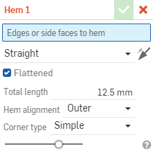
With a Straight hem selected, the hem is aligned along the sheet metal material. With Flattened checked, the hem is flush against the sheet metal material, using the Sheet metal model's Minimal gap value for the space between hem and sheet metal. Uncheck Flattened to specify the hem's Inner radius measurement. Enter the Total length of the hem from the outer most edge of the hem to the end of the hem.
If instead you select the Rolled hem type, the hem is rolled over the edge. Enter the Inner radius measurement for the hem. Then enter the angle of the roll, greater than 180 degrees, to determine how far the roll extends towards the sheet metal wall.
If instead you select the Teardrop hem type, the hem length extends from the very back of the curved edge to the front edge, forming a teardrop shape. Enter an Inner radius measurement for the hem bend. Check Use minimal gap to use the Minimal gap value specified in the Sheet metal model feature. This is the measurement representing the distance between the end of the rolled hem and the sheet being hemmed. When Minimal gap is unchecked, enter the Gap measurement. Next, enter the Total length of the hem from the outer most edge of the hem to the end of the hem.
For all hem types, specify the Hem Alignment and Corner type. Hem alignment specifies how the hem is aligned in relation to the outer edge of the hem bend. Outer alignment aligns the outside edge of the hem with the edge of the sheet metal. In place alignment adds the outside edge beginning at the edge of the sheet metal. Corner type defines how hems come together on the sheet metal. Simple results in a straight line in the flat view (linear in the flat). Closed closes up the corner as much as possible so the corner can be welded, and results in more complicated geometry in the flat view.
Click the checkmark to accept the new hem.
To create one or more hems on existing sheet metal parts, first have a sheet metal part in the Part Studio:
- While in a Part Studio, click
 .
.
- Select the edges or side faces along which to create hems.
- Choose a direction using the Flip arrow. (Toggle the direction with this arrow.)
- Specify the Hem type:
 Tear drop
Make the hem a tear drop shape; the length extends from the very back of the curved edge to the front edge of the hem.

Specifications:
Inner radius - The measurement of the inner radius of the hem bend.
Minimal gap - When checked, this field uses the value specified as the Minimal gap value specified in the Sheet metal model feature. (The value representing the distance between the end of the rolled hem and the sheet being hemmed.)
Gap - When Minimal gap is unchecked, specify the specific gap you require.
Total length - The length of the hem from the outer most edge of the hem to the end of the hem.
Hem alignment - The alignment of the hem in relationship to the outer edge of the hem bend: Outer aligns the outside edge of the hem with the edge of the sheet metal. In place adds the outside edge beginning at the edge of the sheet metal:
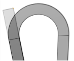
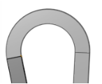
A tear drop hem with Outer specified, first image, and In place specified, second image
Corner type - Where hems come together on sheet metal, specify which type of corner to form: Simple results in a straight line in the flat view (linear in the flat). Closed closes up the corner as much as possible so the corner can be welded and results in more complicated geometry in the flat:
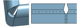
A Simple corner in the model and in the flat view, above
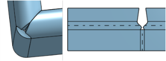
A Closed corner in the model and in the flat view, above
 Rolled
Roll the hem over the edge, using a specific radius.

Specifications:
Inner radius - The measurement of the inner radius of the hem.
Angle - The angle of the roll, determining how far the roll extends towards the sheet metal wall.


The first image shows an angle of 270 degrees and the second image has an angle of 200 degrees
Hem alignment - The alignment of the hem in relationship to the outer edge of the hem bend: Outer aligns the outside edge of the hem with the edge of the sheet metal. In place adds the outside edge beginning at the edge of the sheet metal:


A rolled hem with Outer specified, first image, and In place specified, second image
Corner type - Where hems come together on sheet metal, specify which type of corner to form: Simple results in a straight line in the flat view (linear in the flat). Closed closes up the corner as much as possible so the corner can be welded and results in more complicated geometry in the flat:
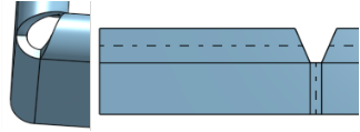
A Simple corner in the model and in the flat view, above
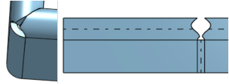
A Closed corner in the model and in the flat view, above
 Straight
Align the hem along the sheet metal material.

Specifications:
Flattened - When checked, places the hem flush against the sheet metal material, using the Sheet metal model's Minimal gap for the space between hem and sheet metal.
Inner radius - When Flattened is unchecked, you can specify measurement of the inner radius of the hem.
Total length - The length of the hem from the outer most edge of the hem to the end of the hem.
Hem alignment - The alignment of the hem in relationship to the outer edge of the hem bend: Outer aligns the outside edge of the hem with the edge of the sheet metal. In place adds the outside edge beginning at the edge of the sheet metal:
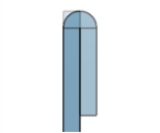
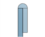
A rolled hem with Outer specified, first image, and In place specified, second image
Corner type - - Where hems come together on sheet metal, specify which type of corner to form: Simple results in a straight line in the flat view (linear in the flat). Closed closes up the corner as much as possible so the corner can be welded and results in more complicated geometry in the flat:
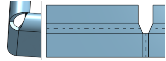
A Simple corner in the model and in the flat view, above
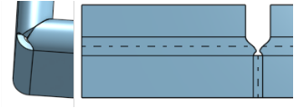
A Closed corner in the model and in the flat view, above
-
Click
 to accept the feature; the Hem is listed in the Feature list.
All dialog selections will default to previously specified values for subsequent hem operations, across sessions and documents.
When you have the flat view open, notice in the bend table that hems are listed there, along with their radius and angle. You can move them up or down in the table, but currently you cannot edit them in the table.
Create one or more hems on existing sheet metal parts.
![]()
To create one or more hems on existing sheet metal parts, first have a sheet metal part in the Part Studio:
- While in a Part Studio, click
 .
.
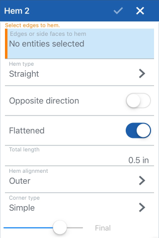
- Select the edges or side faces along which to create hems.
- Choose a direction using the Flip arrow. (Toggle the direction with this arrow.)
- Specify the Hem type:
 Tear drop
Make the hem a tear drop shape; the length extends from the very back of the curved edge to the front edge of the hem.

Specifications:
Inner radius - The measurement of the inner radius of the hem bend.
Minimal gap - When checked, the Minimal gap uses the value specified as the Minimal gap in the Sheet metal model feature.
Gap - When Minimal gap is unchecked, specify the specific gap you require.
Total length - The length of the hem from the outer most edge of the hem to the end of the hem.
Hem alignment - The alignment of the hem in relationship to the outer edge of the hem bend: Outer aligns the outside edge of the hem with the edge of the sheet metal. In place adds the outside edge beginning at the edge of the sheet metal:


A tear drop hem with Outer specified, first image, and In place specified, second image
Corner type - Where hems come together on sheet metal, specify which type of corner to form: Simple results in a straight line in the flat view (linear in the flat). Closed closes up the corner as much as possible so the corner can be welded and results in more complicated geometry in the flat:

A Simple corner in the model and in the flat view, above

A Closed corner in the model and in the flat view, above
 Rolled
Roll the hem over the edge, using a specific radius.

Specifications:
Inner radius - The measurement of the inner radius of the hem.
Angle - The angle of the roll, determining how far the roll extends towards the sheet metal wall.


The first image shows an angle of 270 degrees and the second image has an angle of 200 degrees
Hem alignment - The alignment of the hem in relationship to the outer edge of the hem bend: Outer aligns the outside edge of the hem with the edge of the sheet metal. In place adds the outside edge beginning at the edge of the sheet metal:


A rolled hem with Outer specified, first image, and In place specified, second image
Corner type - Where hems come together on sheet metal, specify which type of corner to form: Simple results in a straight line in the flat view (linear in the flat). Closed closes up the corner as much as possible so the corner can be welded and results in more complicated geometry in the flat:

A Simple corner in the model and in the flat view, above

A Closed corner in the model and in the flat view, above
 Straight
Align the hem along the sheet metal material.

Specifications:
Flattened - When checked, places the hem flush against the sheet metal material, using the Sheet metal model's Minimal gap for the space between hem and sheet metal.
Inner radius - When Flattened is unchecked, you can specify measurement of the inner radius of the hem.
Total length - The length of the hem from the outer most edge of the hem to the end of the hem.
Hem alignment - The alignment of the hem in relationship to the outer edge of the hem bend: Outer aligns the outside edge of the hem with the edge of the sheet metal. In place adds the outside edge beginning at the edge of the sheet metal:


A rolled hem with Outer specified, first image, and In place specified, second image
Corner type - - Where hems come together on sheet metal, specify which type of corner to form: Simple results in a straight line in the flat view (linear in the flat). Closed closes up the corner as much as possible so the corner can be welded and results in more complicated geometry in the flat:

A Simple corner in the model and in the flat view, above

A Closed corner in the model and in the flat view, above
-
Click
 to accept the feature; the Hem is listed in the Feature list.
All dialog selections will default to previously specified values for subsequent hem operations, across sessions and documents.
When you have the flat view open, notice in the bend table that hems are listed there, along with their radius and angle. You can move them up or down in the table, but currently you cannot edit them in the table.
-
 Flange - Create a wall for each edge selected, connected to the selected edge with a bend.
 -
 Hem - Create a hem for each edge/face selected, on an existing sheet metal part.
 -
 Tab - Add a tab to a sheet metal flange.
 -
 Bend - Bend a sheet metal model along a reference line, with additional bend control options.
 -
 Form - Create form features on existing sheet metal models. Forms can be selected from the current document, other documents, or a predefined library of sheet metal forms.
 -
 Loft - Create sheet metal models that connect two profiles.
 -
 Make joint - Convert the intersection of two walls into a joint feature, either a bend (walls joined by cylindrical geometry) or a rip (small gap between two walls).
 -
 Corner - Modify a corner type and relief scale.
 -
 Bend relief - Modify a bend relief (the small cut made where the bend end meets the free edge), depth and relief width.
 -
 Modify joint - Make changes to an existing joint, such as converting a bend to a rip. Currently available through the flat view table.
 -
 Corner break - Break the corner on existing sheet metal parts by applying a fillet or chamfer. Select a corner edge or vertex and specify corner break type and distance. It is recommended to use this feature after all flanges and joints of the Sheet metal model are finalized.
 -
 Sheet metal table and flat view - Open and close the Rip/Bend tables and the visualization of the sheet metal model flat pattern. Use this table to convert rips to bends and vice versa.
 -
 Finish sheet metal model - Closes (deactivates) the Sheet metal model; creates a feature in the Feature list.