 Sheet Metal Corner Break
![]()
![]()
![]()
Break the corner on existing sheet metal parts by applying a fillet or chamfer. Select a corner edge or vertex and specify corner break type and distance. It is recommended to use this feature after all flanges and joints of the Sheet metal model are finalized.
One of the final steps in sheet metal design involves breaking sharp corners to prevent injuries and snags. Onshape’s Sheet metal corner break feature accomplishes this by adding a fillet or chamfer to any selected corners.
Reserve Corner breaks for the final features of a Sheet metal part. Once a Corner break feature is applied, the Joint type and Style cannot be modified.
Corner breaks apply to any corner in a sheet metal part, even those created due to Bend relief cuts.
Start a new Corner break feature. Select either the Fillet or Chamfer tab, then select one or more corner edges or vertices of a sheet metal part. The corners can be selected in the formed or flattened state.
For a Fillet, select either Radius or Width for the Measurement. Additionally, set the Control option for the fillet to either Distance, Conic, or Curvature.
Set the radius or width value to dimension the fillet. For a conic-based fillet, set the Rho value. For a curvature-based fillet, set the Magnitude.
For a fillet consisting of two radii blending together, check Asymmetric and enter the Second radius. Toggle the Flip asymmetric arrows when necessary.
Both Distance and Conic have an option to Allow edge overflow. Checking this option allows the fillet feature to modify the edges on the face created by the fillet, leading to a smooth, continuous surface. When you do not check this option, Onshape preserves the edges on the filleted face.
For a Chamfer, set the Measurement to Offset or Tangent. Then, select a Chamfer type. Equal distance extends the chamfer an equal distance from the edge in both directions. Two distances extends the chamfer by each distance value entered. Distance and angle extends the chamfer a specified distance in one direction and a specified angle in the other. With both these options, you can toggle the Opposite direction arrow to switch the side.
To create a filleted corner break on a sheet metal model:
- While in a Part Studio with an existing sheet metal model, click
Corner break (
 ).
).
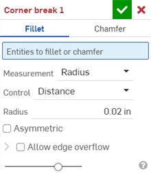
- Select Fillet for the corner break type.
- Select a corner edge or vertex on the sheet metal model in the graphics area. A corner edge or vertex can also be selected in the flat view section of the Sheet metal model and flat view.
- Select the measurement type, either:
- Radius - Specify the radial measurement of the fillet.
- Width - Specify the distance between the two ends of the fillet (a constant width).
- Select a Control type:
- Distance - Fillet has a circular edge with the radius value entered. Onshape remembers this value when creating new fillets.
- Conic - Fillet has a conical edge with the radius value you enter and optionally a Rho value to define the style of the fillet:

Rho values: 0.25 (left; elliptical curve); 0.5 (middle; parabolic curve); 0.999 (right; hyperbolic curve - zoomed in)
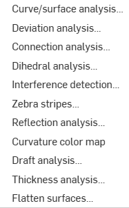
- Curvature - Fillet matches the curvature of the surrounding edges with a radius value you enter and optionally a Magnitude value between 0 and .999 to adjust the tangency. Turn Zebra stripes on (from the Show analysis tools menu) to see the tangency more clearly:
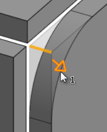
When entering a radius value you can also use the drag manipulator, as indicated in the image below by an arrow, to visualize the fillet and approach an estimated value:
Onshape remembers the selection for Measurement type and value and opens the dialog with the last selected option in subsequent operations.
- Check Asymmetric and enter a Second radius to have a different fillet edge radius value on one end of the filleted edge. Click the Flip asymmetric arrow to use the other end of the fillet as the second (asymmetrical) fillet edge.
- By default, Allow edge overflow is disabled. Check to allow the tangent edges to be 'deleted' from the fillet surface, if necessary. The edges that are generated by default strictly constrain the direction of the fillet along the fillet edges. When Allow edge overflow is enabled, the fillet can modify edges on the face created by the fillet to make a smooth, continuous surface. When the option is unchecked, the edges on the filleted face are preserved, resulting in a more free-flowing part.
Click the Allow edge overflow dropdown to open a field where you can select edges to keep.
-
Click the checkmark (
 ) to accept the new Corner break feature.
To create a chamfered corner break on a sheet metal model:
- While in a Part Studio with an existing sheet metal model, click
Corner break (
 ).
).
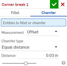
- Select Chamfer for the corner break type.
- Select a corner edge or vertex on the sheet metal model in the graphics area. A corner edge or vertex can also be selected in the flat view section of the Sheet metal model and flat view.
- Select the measurement type, either:
- Offset - Sets the distance entered in the Distance field from the starting edge to the chamfer. This option is edge dependent; computation starts at the first selection and then progresses through the chain.
- Tangent - Sets the distance entered in the Distance field from the intersection of the tangent of the two adjacent faces to the chamfer. This option is NOT edge dependent.
- Select a Chamfer type:
- Equal distance - Chamfer will extend an equal distance from the edge in both directions.
- Two distances - Chamfer will extend a different distances in each direction.
- Distance and angle - Chamfer will extend the specified distance in one direction and by the specified angle in the other.
Onshape remembers the selection for the Chamfer type and opens the dialog with the last selected option in subsequent operations.
- Enter the Distance(s) for the chamfer. Onshape defaults to 45 degrees for the angle, but remembers the last inputted distance value for Equal distance and Distance and angle chamfers.
- If you selected Two distances or Distance and angle, click the arrow button to flip the direction of all edges, or specify individual edges to flip in the Direction overrides field.
-
Click the checkmark (
 ) to accept the new Corner break feature.
-
After a Corner break feature is applied, all model Joints' Type (Rip or Bend) and Style (Edge joint or Butt joint) are no longer editable in the Sheet metal table and flat view. It is recommended to add any Corner break features after finalizing all edits to the Sheet metal model's flanges and joints.
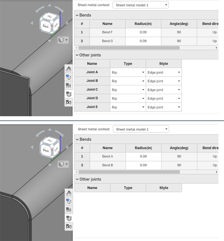
Before Corner break feature applied (top); after Corner break feature applied (bottom)
-
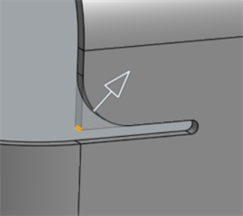
You can use Corner break to apply fillets or chamfers to Bend relief edges and vertices, in addition to corners:
-
You cannot add multiple fillets, chamfers, or a combination of both on corners using a single Corner break feature. Create an additional Corner break feature to add an additional fillet or chamfer to any vertex or edge of a previously-existing Corner break feature:
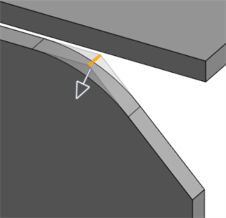
Fillet applied to a chamfered edge using a second Corner break feature
When a sheet metal model is active (in the process of being created or edited), additional tools are available:
-
 Flange - Create a wall for each edge selected, connected to the selected edge with a bend.
 -
 Hem - Create a hem for each edge/face selected, on an existing sheet metal part.
 -
 Tab - Add a tab to a sheet metal flange.
 -
 Bend - Bend a sheet metal model along a reference line, with additional bend control options.
 -
 Form - Create form features on existing sheet metal models. Forms can be selected from the current document, other documents, or a predefined library of sheet metal forms.
 -
 Loft - Create sheet metal models that connect two profiles.
 -
 Make joint - Convert the intersection of two walls into a joint feature, either a bend (walls joined by cylindrical geometry) or a rip (small gap between two walls).
 -
 Corner - Modify a corner type and relief scale.
 -
 Bend relief - Modify a bend relief (the small cut made where the bend end meets the free edge), depth and relief width.
 -
 Modify joint - Make changes to an existing joint, such as converting a bend to a rip. Currently available through the flat view table.
 -
 Corner break - Break the corner on existing sheet metal parts by applying a fillet or chamfer. Select a corner edge or vertex and specify corner break type and distance. It is recommended to use this feature after all flanges and joints of the Sheet metal model are finalized.
 -
 Sheet metal table and flat view - Open and close the Rip/Bend tables and the visualization of the sheet metal model flat pattern. Use this table to convert rips to bends and vice versa.
 -
 Finish sheet metal model - Closes (deactivates) the Sheet metal model; creates a feature in the Feature list.
To create a filleted corner break on a sheet metal model:
- While in a Part Studio with an existing sheet metal model, tap
Corner break (
 ).
).
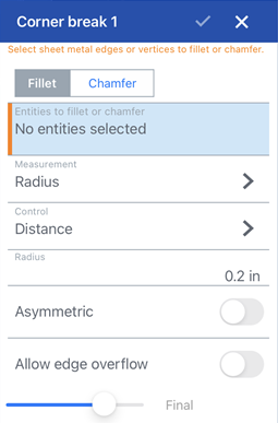
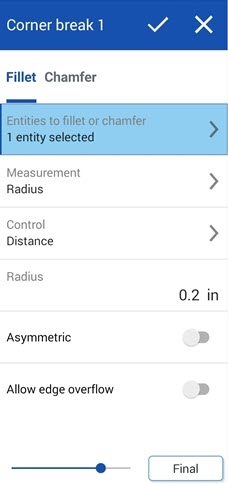
Corner break: Fillet dialog for iOS (first image above) and Android (second image above)
- Tap Fillet for the corner break type.
- Select a corner edge or vertex on the sheet metal model in the graphics area.
- Select the measurement type, either:
- Radius - Specify the radial measurement of the fillet.
- Width - Specify the distance between the two ends of the fillet (a constant width).
- Select a Control type:
- Distance - Fillet has a circular edge with the radius value entered. Onshape remembers this value when creating new fillets.
- Conic - Fillet has a conical edge with the radius value you enter and optionally a Rho value to define the style of the fillet:

Rho values: 0.25 (left; elliptical curve); 0.5 (middle; parabolic curve); 0.999 (right; hyperbolic curve - zoomed in)
- Curvature - Fillet matches the curvature of the surrounding edges with a radius value you enter and optionally a Magnitude value between 0 and .999 to adjust the tangency.
When entering a radius value you can also use the drag manipulator, as indicated in the image below by an arrow, to visualize the fillet and approach an estimated value:
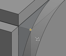
- Toggle Asymmetric on and enter a Second radius to have a different fillet edge radius value on one end of the filleted edge. Toggle the Flip asymmetric arrow to use the other end of the fillet as the second (asymmetrical) fillet edge.
- By default, Allow edge overflow is toggled off. Toggle this option on to allow the tangent edges to be 'deleted' from the fillet surface, if necessary. The edges that are generated by default strictly constrain the direction of the fillet along the fillet edges. When Allow edge overflow is enabled, the fillet can modify edges on the face created by the fillet to make a smooth, continuous surface. When the option is toggled off, the edges on the filleted face are preserved, resulting in a more free-flowing part.
Tap the Edges to keep field and select any edges to keep in the graphics area.
- Tap the checkmark to accept the new Corner break feature.
To create a chamfered corner break on a sheet metal model:
- While in a Part Studio with an existing sheet metal model, tap
Corner break (
 ).
).
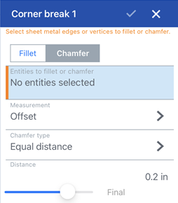
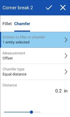
Corner break: Chamfer dialog for iOS (first image above) and Android (second image above)
- Tap Chamfer for the corner break type.
- Select a corner edge or vertex on the sheet metal model in the graphics area.
- Select the measurement type, either:
- Offset - Sets the distance entered in the Distance field from the starting edge to the chamfer. This option is edge dependent; computation starts at the first selection and then progresses through the chain.
- Tangent - Sets the distance entered in the Distance field from the intersection of the tangent of the two adjacent faces to the chamfer. This option is NOT edge dependent.
- Select a Chamfer type:
- Equal distance - Chamfer will extend an equal distance from the edge in both directions.
- Two distances - Chamfer will extend a different distances in each direction.
- Distance and angle - Chamfer will extend the specified distance in one direction and by the specified angle in the other.
- Enter the Distance(s) for the chamfer. Onshape defaults to 45 degrees for the angle, but remembers the last inputted distance value for Equal distance and Distance and angle chamfers.
- If you selected Two distances or Distance and angle, tap the arrow button to flip the direction of all edges, or specify individual edges to flip in the Direction overrides field.
- Tap the checkmark to accept the new Corner break feature.
-
After a Corner break feature is applied, all model Joints' Type (Rip or Bend) and Style (Edge joint or Butt joint) are no longer editable in the Sheet metal table and flat view. It is recommended to add any Corner break features after finalizing all edits to the Sheet metal model's flanges and joints.
-
You can use Corner break to apply fillets or chamfers to Bend relief edges and vertices, in addition to corners:

-
You cannot add multiple fillets, chamfers, or a combination of both on corners using a single Corner break feature. Create an additional Corner break feature to add an additional fillet or chamfer to any vertex or edge of a previously-existing Corner break feature:

Fillet applied to a chamfered edge using a second Corner break feature
When a sheet metal model is active (in the process of being created or edited), additional tools are available:
-
 Flange - Create a wall for each edge selected, connected to the selected edge with a bend.
 -
 Tab - Add a tab to a sheet metal flange.
 -
 Make joint - Convert the intersection of two walls into a joint feature, either a bend (walls joined by cylindrical geometry) or a rip (small gap between two walls).
 -
 Corner - Modify a corner type and relief scale.
 -
 Bend relief - Modify a bend relief (the small cut made where the bend end meets the free edge), depth and relief width.
 -
 Loft - View and modify sheet metal models that connect two profiles.
 -
 Corner break - Break the corner on existing sheet metal parts by applying a fillet or chamfer. Select a corner edge or vertex and specify corner break type and distance. It is recommended to use this feature after all flanges and joints of the Sheet metal model are finalized.
 -
 Finish sheet metal model - Closes (deactivates) the Sheet metal model; creates a feature in the Feature list.