 Sheet Metal Make Joint
![]()
![]()
![]()
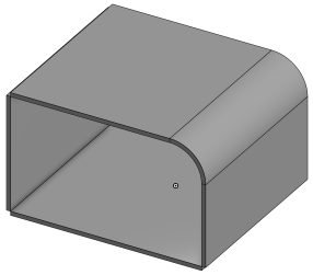
Join or extend existing sheet metal walls into a bend or rip (that is displayed in the Bend/Rip table), creating associativity between the two edges. You have the ability to configure and further define the style of the bend or rip once it is created. To modify an existing joint, use Modify joint.
The Make joint feature joins or extends existing sheet metal walls into a bend or rip (that is displayed in the Bend/Rip table), creating associativity between the two edges. You have the ability to configure and further define the style of the bend or rip once it is created.
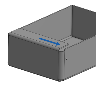
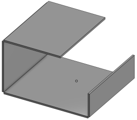
Click the Make joint feature on the Part Studio toolbar. Select the side faces or edges of intersection walls to join. If Rip is selected, select a rip style. Edge joint, Butt joint - Direction 1, or Butt joint - Direction 2. Note that only a 90 degree joint can be styled as a Butt joint. A Non-90 degree joint must be styled as an Edge joint.
If instead you wish to create a bend joint, select Bend from the dropdown. With Use model bend radius selected, the Bend radius in the Sheet metal model feature is used. Uncheck to specify an alternative Bend radius measurement.
Click the checkmark to accept the new joint.
To start a Sheet metal make joint operation:
- While in a Part Studio, click
 .
.
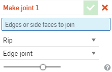
- Select the edges or side faces of intersection walls. This field requires two selections; two edges, two faces, or a face and an edge.
- Select one of the following joint types:
- Bend - Creates a curve between the faces/edges with a bend centerline and a radius. Keep the model properties default for the radius, or uncheck that box and specify a new bend radius.
- Rip - Create an association between the faces/edges where two sheet metal edges meet. When Rip is selected, select one of the following Rip edge types:
- Edge joint - Extends both edges to meet at their inner edges, The minimal gap from the Sheet metal model feature is used to create a gap between the two selections.
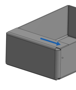
- Butt joint - Direction 1 - Extends the outer edges of the selected face/edge to each other until they meet. The minimal gap from the Sheet metal model feature is used to create a gap between the two seleections. This option is only available for 90 degree joints.
- Butt joint - Direction 2 - Similar to Direction 1, but the handedness of the selected faces/edges is flipped.
-
To convert the rip to a bend, open the
Sheet metal table and flat view
 :
:
When a sheet metal model is active (in the process of being created or edited), additional tools are available:
-
 Flange - Create a wall for each edge selected, connected to the selected edge with a bend.
 -
 Hem - Create a hem for each edge/face selected, on an existing sheet metal part.
 -
 Tab - Add a tab to a sheet metal flange.
 -
 Bend - Bend a sheet metal model along a reference line, with additional bend control options.
 -
 Form - Create form features on existing sheet metal models. Forms can be selected from the current document, other documents, or a predefined library of sheet metal forms.
 -
 Loft - Create sheet metal models that connect two profiles.
 -
 Make joint - Convert the intersection of two walls into a joint feature, either a bend (walls joined by cylindrical geometry) or a rip (small gap between two walls).
 -
 Corner - Modify a corner type and relief scale.
 -
 Bend relief - Modify a bend relief (the small cut made where the bend end meets the free edge), depth and relief width.
 -
 Modify joint - Make changes to an existing joint, such as converting a bend to a rip. Currently available through the flat view table.
 -
 Corner break - Break the corner on existing sheet metal parts by applying a fillet or chamfer. Select a corner edge or vertex and specify corner break type and distance. It is recommended to use this feature after all flanges and joints of the Sheet metal model are finalized.
 -
 Sheet metal table and flat view - Open and close the Rip/Bend tables and the visualization of the sheet metal model flat pattern. Use this table to convert rips to bends and vice versa.
 -
 Finish sheet metal model - Closes (deactivates) the Sheet metal model; creates a feature in the Feature list.
To start a Sheet metal make joint operation:
-
While in a Part Studio, tap
 .
.
- Select the side faces or edges of intersection walls to comprise the rip feature.
- Select a rip style:
- Edge joint
- Butt joint - Direction 1
- Butt joint - Direction 2
Note that only 90° joints can be styled as Butt joints; non-90° joints must be Edge joints.
-
To convert the rip to a bend, open the
Sheet metal table and flat view
 :
:


-
 Flange - Create a wall for each edge selected, connected to the selected edge with a bend.
 -
 Tab - Add a tab to a sheet metal flange.
 -
 Make joint - Convert the intersection of two walls into a joint feature, either a bend (walls joined by cylindrical geometry) or a rip (small gap between two walls).
 -
 Corner - Modify a corner type and relief scale.
 -
 Bend relief - Modify a bend relief (the small cut made where the bend end meets the free edge), depth and relief width.
 -
 Loft - View and modify sheet metal models that connect two profiles.
 -
 Corner break - Break the corner on existing sheet metal parts by applying a fillet or chamfer. Select a corner edge or vertex and specify corner break type and distance. It is recommended to use this feature after all flanges and joints of the Sheet metal model are finalized.
 -
 Finish sheet metal model - Closes (deactivates) the Sheet metal model; creates a feature in the Feature list.