 Sheet Metal Flange
![]()
![]()
![]()
Create a wall for each edge selected for a sheet metal model, connected by a bend.
The Flange feature allows you to create a wall for each edge selected on a sheet metal model, connected by a bend.
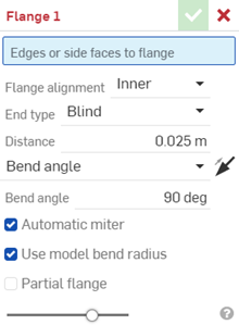
Click the Flange feature tool from the Part Studio toolbar. Select the Edges or side faces to flange. Select the Flange alignment: Inner, Outer, or Middle. Select the flange End type: Blind, Up to entity, or Up to entity with offset. Enter a numerical distance for the flange.
Select an Angle control type to specify how to orient the angle of the flange bend: Bend angle, Align to geometry, or Angle from direction. If Align to geometry is selected, select the geometry to use for alignment in the graphics area. If Angle from direction is selected, select an axis or Mate connector to use for directional alignment. Click the arrow to align the flange in the opposite direction. If Angle from direction is selected, you can use the arrow to reverse the angle direction.
By default, Automatic miter is checked to automatically trim or extend the intersecting flanges for a miter. Uncheck to specify a custom miter angle.
By default, Use model bend radius is checked. The inside bend radius of the sheet metal model is used. Uncheck to enter a custom Bend radius value.
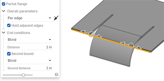
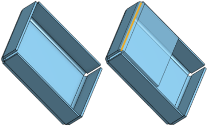
Check Partial flange to specify a flange offset along the flange edge. Enter the offset distance numerically in the dialog or adjust the offset using the manipulator in the graphics area. Specify the Chain type. Per edge ensures the flange is per individual edge. Per chain ensures the flange is per group of edges. Click the arrow to flip the Partial flange side. Keep Hold adjacent edges checked to extend the flange edge the full edge length, or uncheck to limit the flange edge to the length of the partial flange. Set the end conditions: Blind, Up to an entity such as a Part or Mate connector, or Up to entity with offset, where you can set the offset value. Check Second bound to set a secondary bound to offset the secondary direction of the flange, with the same set of options as the primary bound.
When finished, click the checkmark to accept the new flange.
To create a flange:
- While in a Part Studio, click
 .
.

- Select the edges or side faces along which to create flanges.
- Specify the details of the flange:
- Flange alignment:
- Inner - Align the inner wall of the flange wall with the inner edge of the side lip.
- Outer - Align the outer wall of the flange wall with the outer edge of the side lip.
- Middle - Align the mid-plane of the flange wall with a theoretical line halfway between the inner and outer edge of the lip.
- Hold line - Align the bend of a flange at the selected edge or face.

- End type
- Select one of the following End types:
- Blind - Specify a flange distance, measured from the intersection point of the outer edges of the base and the flange to the tip of the flange.
- Distance - Specify a distance value.
- Up to entity - Extend the flange up to a selected entity.
- Up to entity - Select an entity; for example, an edge, face, or plane.
- Up to entity with offset - Extend the flange up to a selected entity and specify the addition of an offset.
- Up to entity - Select an entity; for example, an edge, face, or plane.
- Offset value - Enter an offset value from the selected Up to entity.
- Blind - Specify a flange distance, measured from the intersection point of the outer edges of the base and the flange to the tip of the flange.
- Select an angle control type to specify how to orient the angle of the flange bend:
- Bend angle - Enter a specific angle value, measured from the edge from which to extend the flange.
- Align to geometry
- Align the flange parallel to the selected geometry.
- Parallel to - Select an edge, face, or plane for the flange's parallel alignment.
- Angle from direction
- Align the flange directionally from the selected geometry.
Direction - Select an edge, face, or plane for the flange's directional alignment.
Angle - Enter the flange angle from 1 to 359 degrees from the selected Direction edge, face, or plane.
- Choose a direction using the Opposite side arrow (toggle the direction).
- Check Partial flange to specify a flange offset along the flange edge:

Select Overall parameters:
- Automatic miter
- Check to automatically trim or extend the intersecting flanges for a miter. Uncheck to specify a custom miter angle.
- Miter angle - Enter a custom miter angle value.
- Use model bend radius
- Check to use the inside bend radius specified for the sheet metal model, or leave unchecked to enter a custom Bend radius.
- Bend radius - Enter a custom bend radius value
-
Partial flange - Uncheck if the flange extends the full length of the Edges or side faces to flange. Check to specify a partial flange.
-
Overall parameters - Specify if the flange is:
-
Per edge - Per individual edge.
-
Per chain - Per group of edges.
-
-
Choose a direction using the Flip sides arrow (toggle the direction).
- Hold adjacent edges - Keep checked to extend the flange edge the full edge length, or deselect to limit the flange edge to the length of the partial flange.
-
End Conditions - Set the partial flange end conditions:
-
Bound type - Select one of the following:
- Blind - Specify a flange distance, measured from the intersection point of the outer edges of the base and the flange to the tip of the flange.
- Up to entity - Extend the flange up to a selected entity (for example, an edge, face, or plane).
- Up to entity with offset - Extend the flange up to a selected entity (for example, an edge, face, or plane) and specify the addition of an offset value.
- Offset value - Enter an offset value from the selected Up to entity.
-
Second bound - Check to set a secondary bound to offset the flange's secondary direction, with the same set of options as the primary bound (for example, Bound type).
-
-
-
Click
 to accept the feature; the Flange in the Feature list.
Cross section showing Flange alignment, from left to right: Inner, Outer, Middle, Hold line.
To modify a flange, use a Direct Edit tool such as Move face.

When a sheet metal model is active (in the process of being created or edited), additional tools are available:
-
 Flange - Create a wall for each edge selected, connected to the selected edge with a bend.
 -
 Hem - Create a hem for each edge/face selected, on an existing sheet metal part.
 -
 Tab - Add a tab to a sheet metal flange.
 -
 Bend - Bend a sheet metal model along a reference line, with additional bend control options.
 -
 Form - Create form features on existing sheet metal models. Forms can be selected from the current document, other documents, or a predefined library of sheet metal forms.
 -
 Make joint - Convert the intersection of two walls into a joint feature, either a bend (walls joined by cylindrical geometry) or a rip (small gap between two walls).
 -
 Corner - Modify a corner type and relief scale.
 -
 Bend relief - Modify a bend relief (the small cut made where the bend end meets the free edge), depth and relief width.
 -
 Modify joint - Make changes to an existing joint, such as converting a bend to a rip. Currently available through the flat view table.
 -
 Corner break - Break the corner on existing sheet metal parts by applying a fillet or chamfer. Select a corner edge or vertex and specify corner break type and distance. It is recommended to use this feature after all flanges and joints of the Sheet metal model are finalized.
 -
 Sheet metal table and flat view - Open and close the Rip/Bend tables and the visualization of the sheet metal model flat pattern. Use this table to convert rips to bends and vice versa.
 -
 Finish sheet metal model - Closes (deactivates) the Sheet metal model; creates a feature in the Feature list.
To create a flange:
-
While in a Part Studio, tap
 .
.
- Select the edges or side faces along which to create flanges.
- Specify the details of the flange:
- Flange alignment:
- Inner - Align the inner wall of the flange with the selected edge.
- Outer - Align the outer wall of the flange with the selected edge.
- Middle - Align the mid-plane of the flange wall with the selected edge.
- Hold line - Align the bend of the flange with the selected edge.
- End type of the wall - Select Blind (specify a distance of the flange, measured from the intersection point of the outer edges of the base and the flange to the tip of the flange), Up to entity (select the entity or Mate connector -implicit or explicit- to extend the flange to), Up to entity with offset (select the entity or Mate connector -implicit or explicit- to extend towards and specify the offset value)
- Select an angle control type to specify how to orient the angle of the flange bend:
- Bend angle - Enter a specific angle value, measured from the edge from which to extend the flange.
- Align to geometry - Select an edge or Mate connector (implicit or explicit)to align the flange parallel to.
- Angle from direction - Select an edge or Mate connector (implicit or explicit) from which to measure an angle for the flange.
- Choose a direction using the Flip arrow. (Toggle the direction with this arrow.)
- Automatic miter - Check to automatically trim or extend the intersecting flanges for a miter. Leave unchecked to specify a custom miter angle
- Use model bend radius - Check to use the inside bend radius specified for the sheet metal model, or leave unchecked to enter a custom value (Bend radius)
- Flange alignment:
- Select Partial flange to specify a flange offset along the flange edge:
Chain type - Specify if the flange is per edge (individual edge) or per chain (per group of edges).
Flip sides - Select to flip the flange side direction.
Hold adjacent edges - Keep selected to extend the flange edge the full edge length, or deselect to limit the flange edge to the length of the partial flange.
Bound type - Select Blind (specify a distance, or length, of the flange), Up to entity (select the entity or Mate connector -implicit or explicit- to extend the flange to), or Up to entity with offset (select the entity or Mate connector -implicit or explicit- to extend towards and specify the offset value).
Second bound - Select to set a secondary bound to offset the flange's secondary direction, with the same set of options as the primary bound (for example, Bound type).
-
Tap
 to accept the feature; the Flange in the Feature list.
To modify a flange, use a Direct Edit tool such as Move face.

When a sheet metal model is active (in the process of being created or edited), additional tools are available:
-
 Flange - Create a wall for each edge selected, connected to the selected edge with a bend.
 -
 Tab - Add a tab to a sheet metal flange.
 -
 Make joint - Convert the intersection of two walls into a joint feature, either a bend (walls joined by cylindrical geometry) or a rip (small gap between two walls).
 -
 Corner - Modify a corner type and relief scale.
 -
 Bend relief - Modify a bend relief (the small cut made where the bend end meets the free edge), depth and relief width.
 -
 Corner break - Break the corner on existing sheet metal parts by applying a fillet or chamfer. Select a corner edge or vertex and specify corner break type and distance. It is recommended to use this feature after all flanges and joints of the Sheet metal model are finalized.
 -
 Finish sheet metal model - Closes (deactivates) the Sheet metal model; creates a feature in the Feature list.