![]()
![]()
![]()
Available in: Sketch, Part Studio, Assembly
Learn how to use Camera and render options to set up the model's view in the graphics area.
See also: My Account Preferences - Mouse Controls.
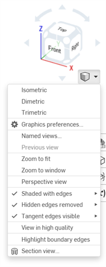
See View navigation and the view cube for more information on these options.
See the following pages for information on menu options:
Some Camera and render options can have their settings default to enabled or disabled:
-
Perspective view / Highlight boundary edges - These options are disabled by default. To set their default to enabled:
-
Click to enable the option.
-
Right-click and select Set as default.
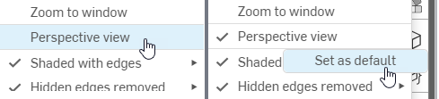
Left-clicking to turn Perspective view on (left), then right-clicking to select Set as default (right)
-
To set the option's default back to disabled:
-
Left click to disable the option.
-
Right-click and select Set as default.
-
-
-
Shaded edges / Hidden edges / Tangent edges - Right-click on any disabled sub-option and click Set as default. This simultaneously enables that option and sets it as the default.
- Front view = Shift 1
- Back view = Shift 2
- Left view = Shift 3
- Right view = Shift 4
- Top view = Shift 5
- Bottom view = Shift 6
- Isometric view = Shift 7
- Section view = Shift X
- Named view = Shift V
![]()
![]()
3D Rotate Lock, when active, locks the user's ability to 3D rotate the graphics area. This is particularly useful when attempting to select and drag an entity.
It is located directly above the View Cube in both Part Studios and Assemblies.
To activate the 3D Rotate Lock, tap the button. To deactivate, tap the button again or commit a feature.
3D Rotate Lock activates by default in certain situations:
- Part Studio - If a sketch is open and an entity is selected, the 3D Rotate Lock turns on by default. This allows for the selection to be dragged without the view rotating. Unlock by tapping the button.
- Assembly - If an instance, Mate connector, or entity is selected, the 3D Rotate Lock turns on by default. This allows for the selection to be dragged without the view rotating. Unlock by tapping the button.
The View cube is located in the upper right corner of the graphics area. When selected, a list of different viewing options appears. Select one to change the view of your graphics area or the view settings of your part(s). This is an easy and quick way to get a well-oriented view of your part(s) without having to 2D/3D rotate or zoom.
- Tap the View cube. A list of options appears.
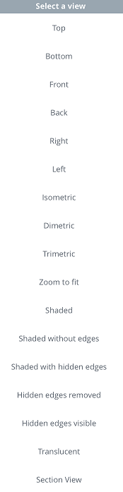
- Tap to select a view option or select Cancel.
- Scroll to see more options.
- Top, Bottom, Front, Back, Right, and Left - Select any of these options for a front-facing view of the respective plane.
- Isometric, Dimetric, Trimetric - Select any of these for the respective angled view.
- Zoom to fit - Select to resize the graphics area to fit the screen. This could result in the view zooming in or out.
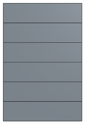
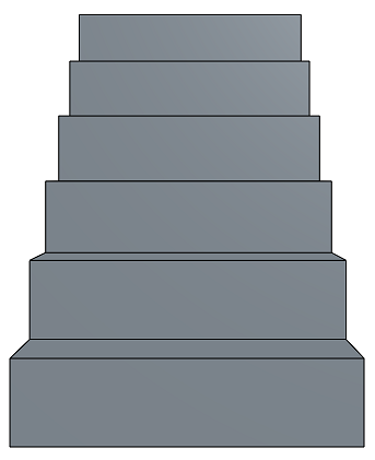
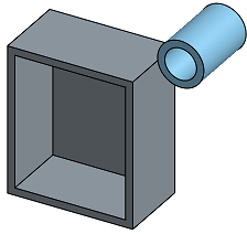
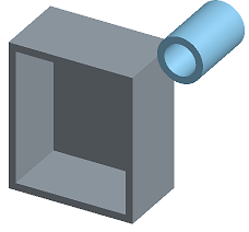
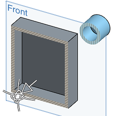
- Perspective View - Toggle perspective view on and off. Perspective view shows the relative distance from the point of view to the model, and creates a vanishing point as the point of view (or imaginary camera) approaches the model. The images below show a front view of the same part without perspective view and with perspective view, respectively.
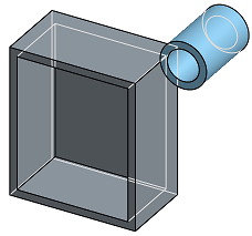
- Shaded - Select to show the part with shaded faces and edges. (Default)
- Shaded without edges - Select to show part shaded, without edges.
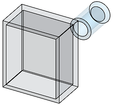
- Shaded with hidden edges - Select to show the part shaded and to show hidden edges (edges that aren't in the direct line of sight).
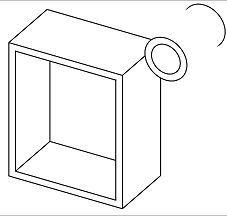
- Hidden edges removed - Select to show the part unshaded, with the hidden edges (edges not in direct line of sight) removed.
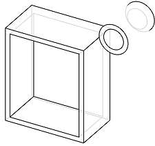
- Hidden edges visible - Select to show the part unshaded, with the hidden edges (edges not in direct line of sight) visible.
- Translucent - Select to show the part as translucent.
- Section View - Select to access a manipulator that allows you to adjust a section view of a part, via a plane or planar face.
You must preselect a plane or planar face before selecting Section View.
Drag the arrow or either directional manipulator to adjust the section view plane that is created from the preselected plane or planar face. In this case, the Front plane is used to create a section view roughly halfway through the parts.