Isometric, Dimetric, and Trimetric Projections
![]()
![]()
![]()
Available in: Part Studio, Assembly, Render Studio, PCB Studio
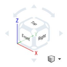
Select from one of 3 projection methods to view the model in the graphics area: Isometric, Dimetric, and Trimetric. These Axonometric projections are used to represent 3D objects on a 2D plane, to simulate perspective.
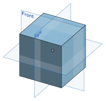
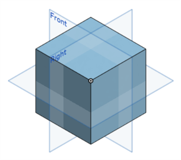
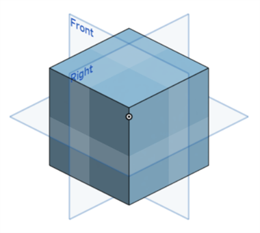
Note the origin point in the example images below to view the difference in the model's axial visualization between the 3 projections.
-
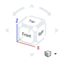
Isometric - All 3 axes (X, Y, and Z) are inclined equally, and the angles between them are all 120 degrees.
-
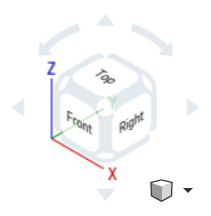
Dimetric - 2 axes share the same scale, with the third axis having a different scale. Angles between the axes are not equal. A Dimetric projection creates a third dimension that appears more compressed or stretched, providing a slightly more realistic view of the model.
-
Trimetric - All 3 axes are inclined at different angles, and all 3 have different scales. The view of the model appears more natural due to a unique foreshortening. This type of view is more common in rendering programs, where realism is required.