 Graphics Preferences

Available in: Part Studio, Assembly
Adjust visualization parameters of the model in the graphics area. Alter general viewport, shaded body, phantom edge, and mesh body parameters, as well as active/inactive sketch line width and colors, and construction line gap and dash lengths.
These options are especially useful when modeling surfaces.
 Accessing Graphics preferences
-
Select Camera and render options, then Graphics preferences:
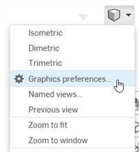
-
The following dialog opens:
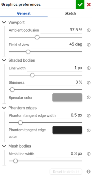
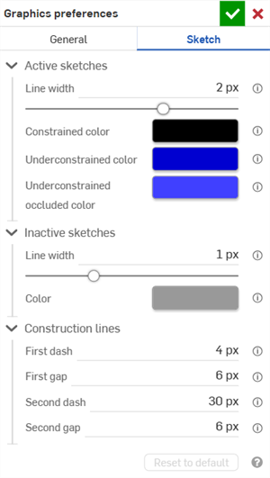
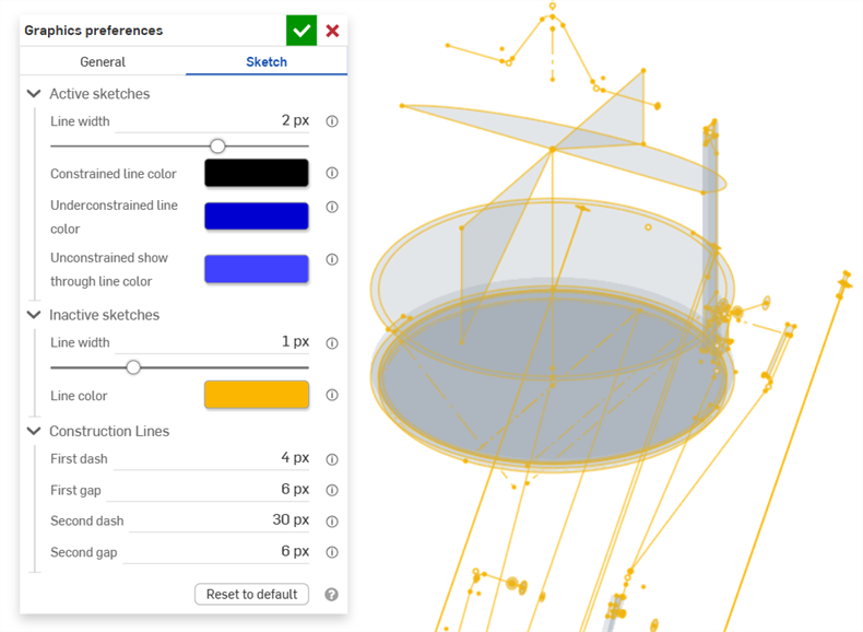
General graphics preferences (left) and Sketch graphics preferences (right)
-
Adjust settings as outlined in the sections below. Click the Reset to default button to return all general and sketch dialog options to their default values.
General preferences
Viewport
-
Ambient occlusion - Controls the intensity of ambient occlusion shading, from 0% - 100% (default: 37.5%). Higher values create soft dark shading along edges, corners, crevices, and other locations where parts meet or intersect. This helps simulate real world indirect light coverage at these locations. Lower values create less shading at these locations.
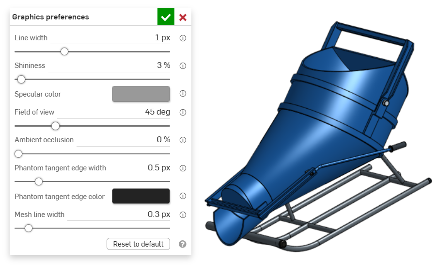
An example of an entity in the graphics area with Ambient occlusion at 0%
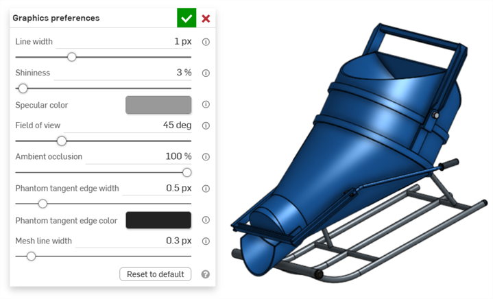
An example of an entity in the graphics area with Ambient occlusion at 100%
-
Field of view (only available when Perspective view is enabled) - Controls the perspective camera field of view. Use the horizontal slider or enter a numerical input from 20 - 120 degrees.
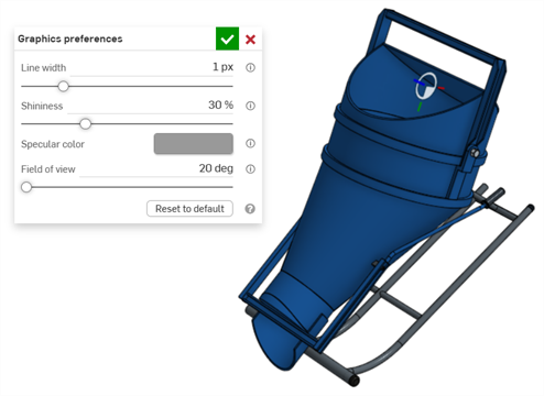
An example of an entity in the graphics area with Field of view set at 20 degrees
Shaded bodies
-
Line width - Controls the line width of surfaces and edges. Use the horizontal slider or enter a numerical input from 0.1 - 3 pixels.
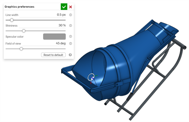
An example of an entity in the graphics area with Line width set at 0.5 px
-
Shininess - Controls the default shininess of shaded surfaces. Use the horizontal slider or enter a numerical input from 1 - 100 percent.
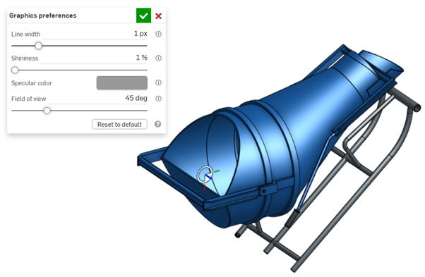
An example of an entity in the graphics area with Shininess set to 1%
-
Specular color - Controls the default specular color of shaded surfaces. Click the color swatch to open the Color picker dialog and select a color.
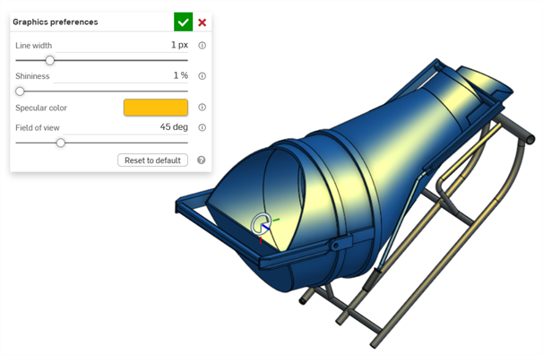
An example of Specular color being edited in the graphics area
-
Section interference color - Controls the default section interference color of overlapped parts or surfaces. Click the color swatch to open the Color picker dialog and select a color.
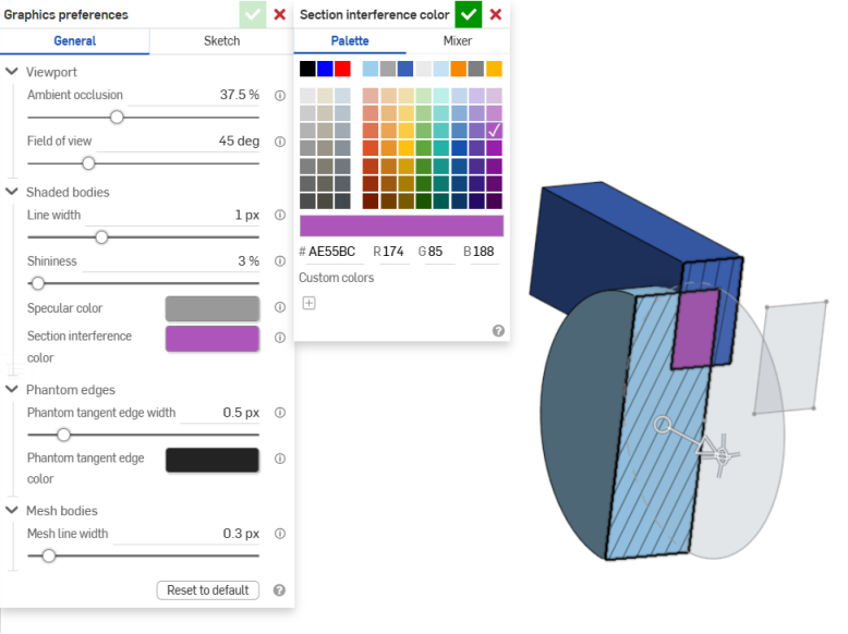
An example of Section interference color being edited in the graphics area
Phantom edges
-
Phantom tangent edge width - If Tangent edges are set to phantom, this controls the line width of those edges, from 0.1 - 3 px (default: 0.5 px).
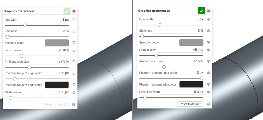
An example of an entity in the graphics area with Phantom tangent edge width set to 0.5 px (left) and 3px (right)
-
Phantom tangent edge color - If Tangent edges are set to phantom, this controls the default color of those edges. Click the color swatch to open the Color picker dialog and select a color.
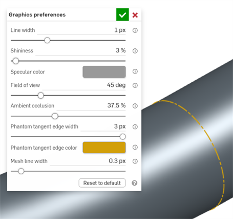
Mesh bodies
-
Mesh line width - Controls the line width of mesh surfaces and edges, from 0.1 - 3 px (default: 0.3 px).
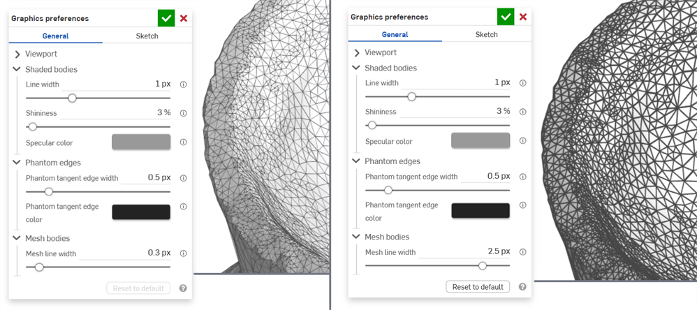
An example of an entity in the graphics area with Mesh line width set to 0.3 px (left) and 2.5 px (right)
Sketch preferences
Active sketches
-
Line width - Controls the line width of active sketches. Use the horizontal slider or enter a numerical input from 0.1 - 3 pixels.
-
Constrained line color - Controls the default color of constrained lines or points. Click the color swatch to open the Color picker dialog and select a color.
-
Underconstrained color - Controls the default color of underconstrained lines and points. Click the color swatch to open the Color picker dialog and select a color.
-
Underconstrained occluded color - Controls the default color of underconstrained occluded lines and points. These are lines and points that are obscured by parts in the graphics area. Click the color swatch to open the Color picker dialog and select a color.
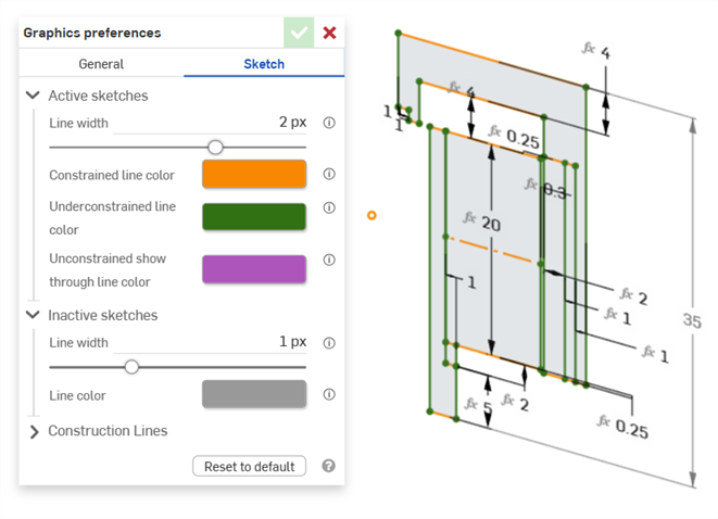
Example showing constrained and underconstrained line colors in an active sketch
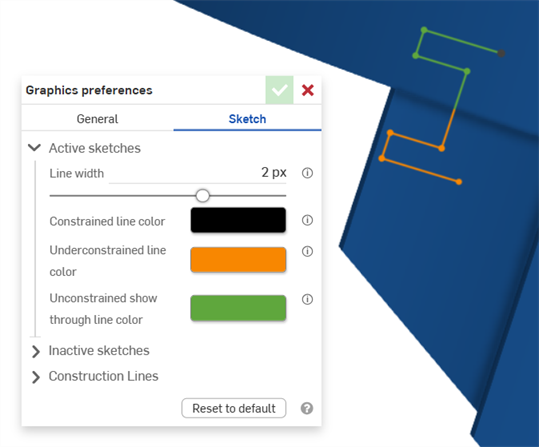
Example showing underconstrained line colors in an active sketch. Green shows the sketch segments obscured by a part in the Graphics area.
Inactive sketches
-
Line width - Controls the line width of inactive sketches. Use the horizontal slider or enter a numerical input from 0.1 - 3 pixels.
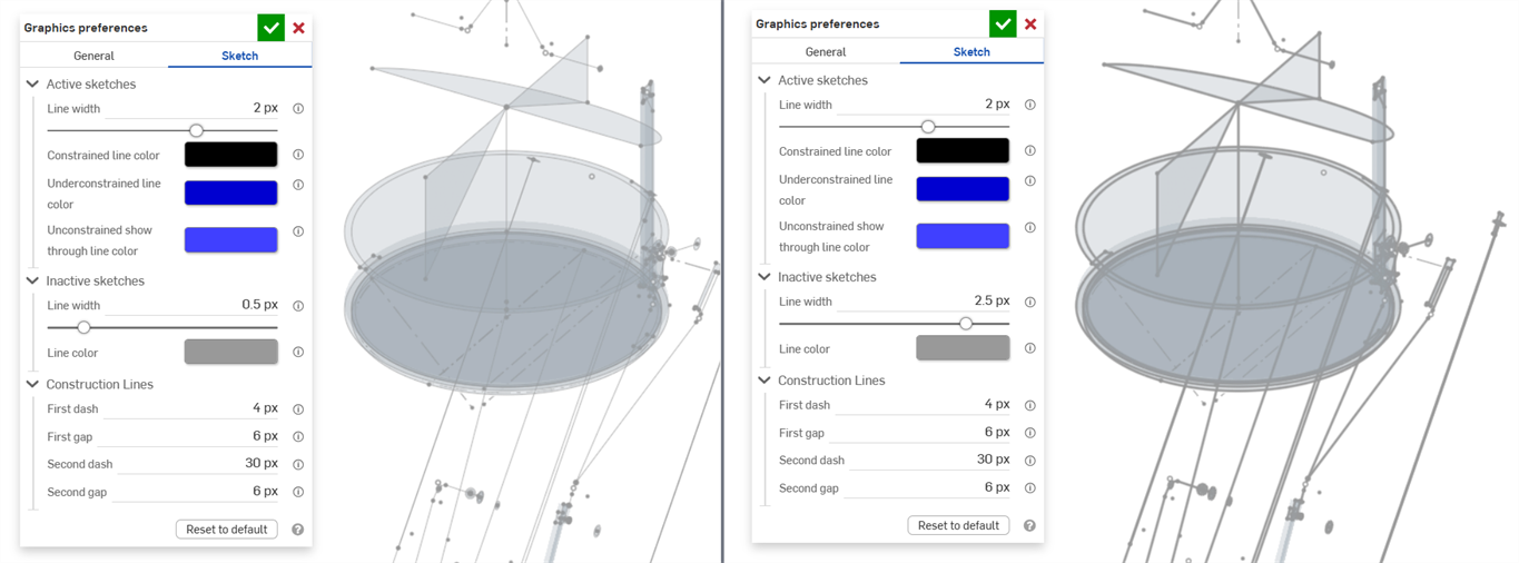
-
Line color - Controls the default color of lines and points of inactive sketches. Click the color swatch to open the Line color dialog to select a color from the Color picker.
Construction lines
-
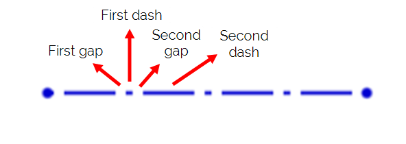
First dash - Controls the length of the first dash in the construction line stipple pattern. Enter a value from 1-50 pixels (default is 4 px.).
-
First gap - Controls the length of the first gap in the construction line stipple pattern. Enter a value from 0-50 pixels (default is 6 px.).
-
Second dash - Controls the length of the second dash in the construction line stipple pattern. Enter a value from 1-50 pixels (default is 30 px.).
-
Second gap - Controls the length, in pixels, of the second gap in the construction line stipple pattern. Enter a value from 0-50 pixels (default is 6 px.).