 Section View
![]()
![]()
![]()
Available in: Part Studio, Assembly
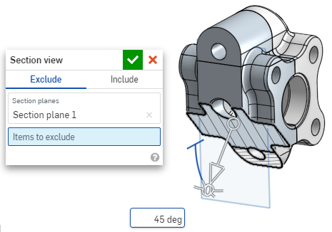
Section view allows for the selection of one or many planes, Mate connectors, cylindrical faces, conical faces, or planar faces to use for sectioning. It can also be used to select a default plane. Section view can be turned on through the Camera and render options menu, or by selecting Section view in the context menu.
Once the manipulator is visible, it can be moved via the ball (open circle at its center) and snapped to any inference point on the part, surface, or assembly. Sectioned items are viewable in both Part Studios and Assemblies:
- Select one or many planes, Mate connectors, cylindrical faces, conical faces, or planar faces on the part or surface.
- Expand the Camera and render options menu
 and select Section view (shown below). Alternatively, right-click on a part in the Part Studio or an assembly in an Assembly tab, and select Section view from the context menu.

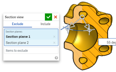
- The part/surface is sectioned at the point chosen in step 1 above (cylindrical face, conical face, planar face, plane, or Mate connector). A manipulator appears at the last location selected and a dialog opens listing selections:
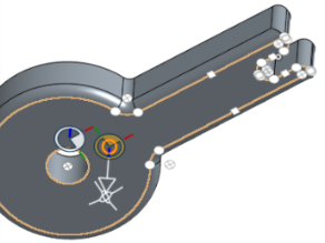
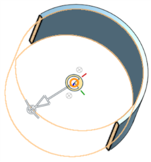
- Click and drag the open circle (ball) of the manipulator to position it. You can snap it to any inference point on the part or assembly, including the centroids of cylinders (the white marks below indicate inference points):
- Use the manipulator to change the depth and/or angle of the section.
- Use the arrow to change the depth, dragging in one direction or another. Click the manipulator to flip the direction of the view.
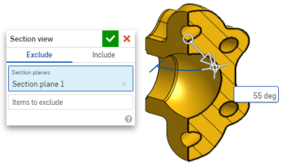
- Use the angle indicators to drag at an angle.
- Use the numeric field in the graphics area to type the depth or angle of the view.
- To select a different sectioning plane while the dialog box remains open, click on the desired location for the new sectioning plane, and a new manipulator and section plane appears.
To view the section normal to the section view plane, use shortcut key N or right-click and select View normal to from the context menu.
- To exclude a part or parts (/surface or surfaces) from being sectioned, activate the Items to exclude field, then make your selections in the graphics area:
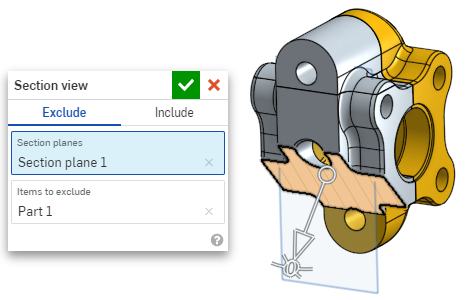
-
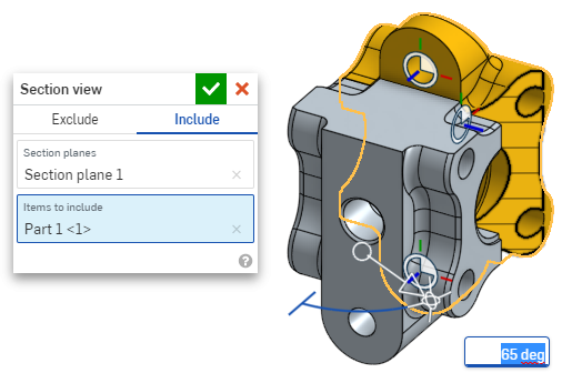
To include a part or parts (/surface or surfaces) in the section, select the Include tab, then select the items to include in the graphics area:
To move the model while in section view, click out of the dialog box to close it, then manipulate the model as desired.
- Click the Select default plane icon
 in the dialog box to open the default plane options in the graphics area:
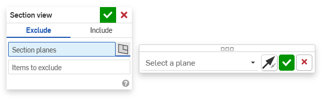
-
Select a default plane from the dropdown menu and the Section view dialog box will update accordingly.
Optionally, click the Flip plane icon to easily toggle between front/back, top/bottom or right/left views.
-
Click the green checkmark in the Select a plane options dialog to save and close the default plane options but keep the Section view dialog box open, or click the green checkmark in the Section view dialog box to save and close both dialogs.
-
Select Turn off section view from the Camera and render options menu
or context menu when finished.
You can also turn on Section view before making any selections.
If intersecting parts exist, they are rendered in red.
If Section view is not turned off and the dialog box is closed, open the dialog again by double-clicking on the section plane. Alternatively, click the Camera and render options menu
![]() or right-click on the part or assembly to access the context menu, and select Edit section view.
or right-click on the part or assembly to access the context menu, and select Edit section view.
You can use Section view and then save the view as a Named View.
You can also use the Measure tool on faces, edges, and vertices while in a Section view. See Measure tool for more information.