 鈑金模型
鈑金模型
![]()
![]()
![]()
藉由轉換現有零件,擠出草圖曲線 (包括用來建立軋延鈑金的弧與樣條),或加厚面或草圖來建立鈑金零件。
藉由轉換現有零件,擠出草圖曲線 (包括用來建立軋延鈑金的弧與樣條),或加厚面或草圖來加入至鈑金零件。在使用中鈑金模型上的所有操作都會自動出現為展開圖樣, 且接合與彎折會列在鈑金表格中。會即時提供摺疊、展開圖樣與表格視圖,且會同步更新。鈑金模型可由多個零件組成,多個鈑金模型可以是同時使用中。
鈑金模型工具會啟用鈑金特徵。因此,影響鈑金模型的特徵會以鈑金片的形式影響鈑金。完成鈑金工具會停用鈑金特徵,讓特徵以 3D 模型而非鈑金的形式影響模型。
例如,當鈑金模型是啟用時,任何貫穿鈑金的特徵是垂直於牆面的,但當鈑金停用時,貫穿牆面的特徵會受限於特徵與牆面間的角度。
您也可以使用其他的鈑金工具來建立凸緣、定義與修改接合、將彎折轉換為裂口 (或裂口轉換為彎折)、定義轉角參數、以及同時以 3D 零件與展開視圖來檢視鈑金零件。Onshape 同時提供列出彎折與裂口的鈑金表格,您可於其中編輯轉角半徑與接合類型,並建立鈑金零件的工程圖。
這個影片說明如何使用「轉換」操作建立一個鈑金模型。
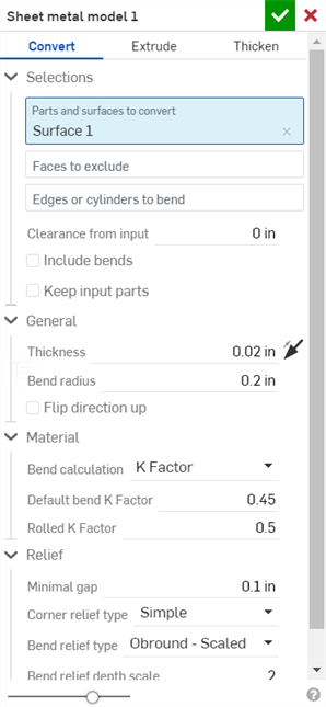
按一下 Part Studio 工具列中的「鈑金模型」特徵工具。根據預設,鈑金的操作類型是「轉換」。請保留選取這個類型。
在圖形區域中選擇要轉換的零件和曲面。選擇要從操作中「排除的面」。接著選擇用來定義彎折的邊線;未選取的邊線會變為裂口。沒有選取至 「要彎折的邊線或圓柱」欄位中的弧或樣條會變為相切的接合,而不是彎折。
核取「包含彎折」來將彎折包括在餘隙值之間。
核取「保留輸入零件」來保留一開始選取的零件 (被鈑金所封閉)。
按一下「一般」下拉清單並輸入鈑金的「厚度」。按一下箭頭來反轉厚度的方向。輸入「折彎半徑」來調整所建立折彎的內部半徑。按一下「反轉方向朝上」來反轉鈑金模型的方位。當定義彎折相對於模型是朝上還是朝下時是相當有用的。
使用「材料」與「離隙」下拉清單選項來進一步定義鈑金模型。
按一下核取記號來接受新的鈑金模型。
封住現有的零件來建立鈑金模型:
- 在 Part Studio 中按一下
 。
。
- 選擇鈑金操作的類型:轉換
- 選擇要封住的零件。
- 選擇要排除在操作之外的面。
- 選擇要用來定義彎折的邊線;未選取的邊線會變為裂口。
沒有選取至 「要彎折的邊線或圓柱」欄位中的弧或樣條會變為相切的接合。請參考下方的範例。
- Specify applicable options:
- Clearance from input - The relative offset between the sheet metal and the part selected to be enclosed by the sheet metal
- Include bends - Check this to include the bend within the clearance value
- Keep input parts - Keep the selected parts (enclosed by the sheet metal) or not
- Thickness - The thickness of the sheet metal
- Bend radius - The inside radius of the bends created
- Flip direction up - Reverses the orientation of the sheet metal model and flat view. This is useful when defining whether bends are up or down, relative to the model.
- 彎折計算 - 決定計算彎折的方式。選項有:
- K 係數 (預設) - 使用中立軸與材料厚度的比例。
- 彎折裕度 - 使用彎折相切點之間的中立線弧長。
- 彎折扣除 - 使用凸緣長度總合 (從邊線到頂端) 與初始展開長度間的差異。
會將在這裡選擇的彎折計算用為鈑金表格中的一個欄位。可以自訂每個彎折並可從表格中直接編輯。詳細資訊請參考鈑金表格與展開視圖。
- Default bend K Factor - The fraction of material thickness on which the neutral axis lies on a bend. (Default is 0.45.)
- Rolled K Factor - The fraction of material thickness on which the neutral axis lies on a section of rolled wall. (Default is 0.5.)
- Minimal gap - The smallest gap between the sheet metal edges defining a rip
- Corner relief type -
- Square - Sized
Flat view:
 3D view:
- Rectangle - Scaled
Flat view:
 3D view:
- Round - Sized
Flat view:
 3D view:
- Round - Scaled
Flat view:
 3D view:
- Closed
Flat view:
 3D view:
- Simple
Flat view:
 3D view:
- Square - Sized
- Corner relief scale - The scale of the corner opening (for Scaled openings), a value between 1.00 and 2.00.
- Corner relief width - The measurement of the width of the corner opening (for Sized openings), in default units or specified units.
- Bend relief type - The shape of the bend relief:
- Rectangle - Scaled

- Obround - Scaled

- Tear

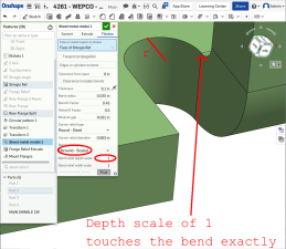
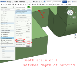
- Bend relief depth scale - A value between 1.00 and 5.00. Once you enter a value it becomes the default across all documents.
A value of 1 results in an obround bend relief perfectly touching the bend and a rectangular bend relief matches the depth of the obround:
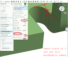
任何超過 1 的值會根據此公式:((深度比例 -1) * 彎折半徑):
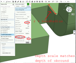
- Bend relief width scale - A value between 0.0625 and 2.00. The width of the bend relief is calculated via the formula: thickness * width scale. Once you enter a value it becomes the default across all documents.
- 按一下
 來接受特徵;鈑金模型特徵會列在「特徵」清單中。
 - 請於此時套用任何其他特定於鈑金的特徵。
- 如果您要繼續將非鈑金特徵加入零件中,請按一下完成鈑金模型
 。
。

您可以從繞單一軸旋轉的圓錐零件建立鈑金。
這個影片說明如何使用「擠出」操作建立一個鈑金模型。
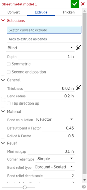
按一下 Part Studio 工具列中的「鈑金模型」特徵工具。選擇 [擠出] 鈑金模型操作。在圖形區域中選擇「要擠出的草圖曲線」。選擇性地選擇「擠出為彎折的弧」。這樣會使得任何所選的弧被建立為彎折 (而非相切的接合),並列於彎折表格中,其中半徑會是反灰的。這是因為弧在草圖中已有半徑,所以您無法在彎折表格中編輯半徑。選擇一個「終止類型」:「給定深度」、「成形至下一幾何」、「成形至面」、「成形至零件」或「成形至一頂點」。按一下箭頭來在相反的方向上擠出。
在對話方塊中輸入深度的數值,或在圖形區域中使用操控器。
核取「對稱」(僅能在「給定深度」與「完全貫穿」終止類型中使用) 來在草圖平面的兩個方向擠出。
或者,與其使用「對稱」選項,改核取「第二結束位置」來指定相反的結束位置,使其深度與第一個主深度不同。
在「一般」下拉清單中輸入鈑金的「厚度」。按一下箭頭來反轉厚度的方向。輸入「折彎半徑」來調整所建立折彎的內部半徑。按一下「反轉方向朝上」來反轉鈑金模型的方位。當定義折彎相對於模型是朝上還是朝下時是相當有用的。
使用「材料」與「離隙」下拉清單選項來進一步定義鈑金模型。
按一下核取記號來接受新的鈑金模型。
擠出草圖曲線來建立鈑金模型:
- 在 Part Studio 中按一下
 。
。
- 選擇擠出的鈑金操作。
- 選擇要擠出的草圖曲線。
- 選擇終止類型:給定深度、成形至下一幾何、成形至面、成形至零件、成形至一頂點。
- 對稱 - 選擇這個選項,僅能在「給定深度」終止類型中使用。指定總距離,會相對於草圖平面在兩個方向上各以一半的距離擠出。
- 拖曳或設定深度。
- 設定鈑金的厚度。
- 設定彎折的內部半徑。
- 如果您要反轉鈑金模型的方位與展開視圖,請核取「反轉方向朝上」。
- 選擇彎折計算來決定如何計算彎折。選項有:
- K 係數 (預設) - 使用中立軸與材料厚度的比例。
- 彎折裕度 - 使用彎折相切點之間的中立線弧長。
- 彎折扣除 - 使用凸緣長度總合 (從邊線到頂端) 與初始展開長度間的差異。
會將在這裡選擇的彎折計算用為鈑金表格中的一個欄位。可以自訂每個彎折並可從表格中直接編輯。詳細資訊請參考鈑金表格與展開視圖。
-
指定 K 係數 - 中立軸所在處材料厚度的分數。
- 設定最小間隙 - 鈑金邊線間的最小間隙。
- 轉角止裂類型:
- 正方形 - 尺寸
展開視圖:
 3D 視圖:
- 矩形 - 縮放
展開視圖:
 3D 視圖:
- 圓形 - 尺寸
展開視圖:
 3D 視圖:
- 圓形 - 縮放
展開視圖:
 3D 視圖:
- 封閉
展開視圖:
 3D 視圖:
- 簡易
展開視圖:
 3D 視圖:
- 正方形 - 尺寸
- 轉角止裂比例 - 轉角開口的比例 (針對縮放的轉角),是一個介於 1.00 和 2.00 之間的值。
- 折彎止裂類型 - 折彎止裂的形狀:
- 矩形 - 縮放:

- 圓端 - 縮放:

- 撕裂:

- 折彎止裂深度比例 - 介於 1.00 與 2.00 之間
- 折彎止裂寬度比例 - 介於 0.0625 到 2.00 之間的值
- 按一下
 來接受特徵;鈑金模型特徵會列在「特徵」清單中。
 - 請於此時套用任何其他特定的鈑金特徵,請見下方說明。
- 如果您要繼續將非鈑金特徵加入零件中,請按一下完成鈑金模型
 。
。 - 按一下
 來關閉「鈑金」特徵;「完成鈑金模型」特徵會列在特徵清單中,其中有展開圖樣與列出彎折與接合的鈑金表格:
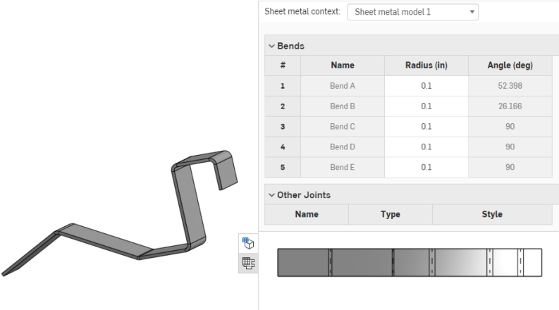
當使用弧或樣條來定義捲曲鈑金壁時,鈑金表格與展開圖樣會稍有不同。在表格中不會列出捲曲鈑金壁的彎折,而是列出相切接合:
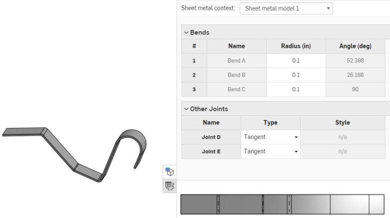
同樣地,展開圖樣中不會有彎折線,因為沒有做出彎折。
您可以從繞單一軸旋轉的圓錐零件建立鈑金。
您可以決定是否要將弧擠出為彎折,不過在「擠出為彎折的弧」欄位啟用的情況下選擇弧 (如下所示):
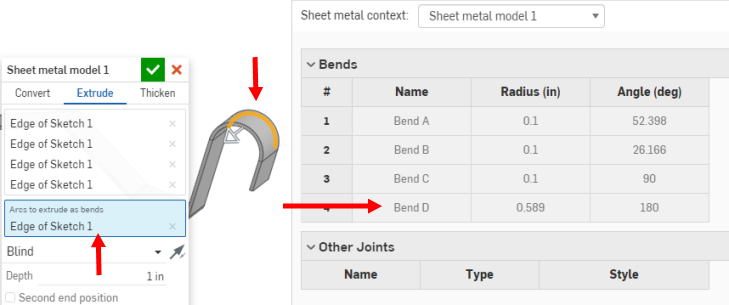
這樣會使得所選的一或多個弧被建立為彎折 (而非相切的接合),並列於彎折表格中,但半徑會是反灰的。這是因為弧在草圖中已有半徑,所以您無法在彎折表格中編輯半徑。
這個影片說明如何使用「加厚」操作建立一個鈑金模型。
按一下 Part Studio 工具列中的「鈑金模型」特徵工具。選擇「加厚」鈑金模型的操作。在圖形區域中選擇「要加厚的面或草圖區域」。
按一下「沿相切面進行」來沿著相切邊線繼續加厚。
選擇「要折彎的邊線或圓柱」;未選取的邊線會變為裂口,在弧與樣條的狀況中則會變為相切的接合。
輸入「來自輸入的餘隙」值:鈑金與選擇來被鈑金所封閉的零件間的相對偏移。
核取「包含彎折」來為彎折包含餘隙。
在「一般」下拉清單中輸入鈑金的「厚度」。按一下箭頭來反轉厚度的方向。輸入「折彎半徑」來調整所建立折彎的內部半徑。按一下「反轉方向朝上」來反轉鈑金模型的方位。當定義折彎相對於模型是朝上還是朝下時是相當有用的。
使用「材料」與「離隙」下拉清單選項來進一步定義鈑金模型。
按一下核取記號來接受新的鈑金模型。
藉由加厚面、曲面或草圖區域來建立鈑金模型:
- 在 Part Studio 中按一下
 。
。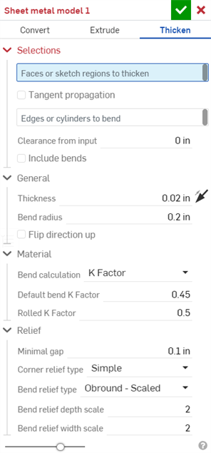
- 選擇鈑金操作的類型:加厚
- 選擇草圖區域、平坦曲面或零件的面。
- 選擇要用來建立彎折的邊線;未選取的邊線會變為裂口,在弧與樣條的狀況中則會變為相切的接合。
- 指定適用的選項:
- 來自輸入的餘隙 - 鈑金與選擇來被鈑金所封閉的零件間的相對偏移
- 餘隙包括彎折 - 核取來為彎折包含餘隙
- 厚度 - 鈑金的厚度
- 彎折半徑 - 所建立彎折的內部半徑
- 反轉方向朝上 - 反轉鈑金模型與展開視圖的方位。當定義彎折相對於模型是朝上還是朝下時是相當有用的。
- 彎折計算 - 決定計算彎折的方式。選項有:
- K 係數 (預設) - 使用中立軸與材料厚度的比例。
- 彎折裕度 - 使用彎折相切點之間的中立線弧長。
- 彎折扣除 - 使用凸緣長度總合 (從邊線到頂端) 與初始展開長度間的差異。
會將在這裡選擇的彎折計算用為鈑金表格中的一個欄位。可以自訂每個彎折並可從表格中直接編輯。詳細資訊請參考鈑金表格與展開視圖。
- 預設彎折 K 係數 - 中立軸所在處的材料厚度分數 (預設是 0.45)。
軋延 K 係數 - 中立軸在捲曲鈑金壁部分的材料厚度分數 (預設是 0.5)。
- 最小間隙 - 鈑金邊線間的最小間隙
- 轉角止裂類型 - 轉角止裂的形狀:
- 正方形 - 尺寸
展開視圖:
 3D 視圖:
- 矩形 - 縮放
展開視圖:
 3D 視圖:
- 圓形 - 尺寸
展開視圖:
 3D 視圖:
- 圓形 - 縮放
展開視圖:
 3D 視圖:
- 封閉
展開視圖:
 3D 視圖:
- 簡易
展開視圖:
 3D 視圖:
- 正方形 - 尺寸
- 轉角止裂比例 - 轉角開口的比例 (針對縮放的轉角),是一個介於 1.00 和 2.00 之間的值。
- 折彎止裂類型:
- 矩形:

- 圓端:

- 撕裂:

- 折彎止裂深度比例 - 介於 1.00 與 2.00 之間。
- 折彎止裂寬度比例 - 介於 0.0625 到 2.00 之間。
- 按一下
 來接受特徵;鈑金模型特徵會列在「特徵」清單中。
 - 請於此時套用任何其他特定的鈑金特徵,請見下方說明。
- 如果您要繼續將非鈑金特徵加入零件中,請按一下完成鈑金模型
 。
。 - 按一下
 來關閉鈑金模型特徵;「完成鈑金模型」特徵會列在「特徵」清單中。

當使用弧或樣條來定義捲曲鈑金壁時,鈑金表格與展開圖樣會稍有不同。在表格中不會列出捲曲鈑金壁的彎折,而是列出相切接合:

同樣地,展開圖樣中不會有彎折線,因為沒有做出彎折。
您可以決定是否要將弧加厚為彎折,不過在「擠出為彎折的弧」欄位啟用的情況下選擇弧 (如下所示):
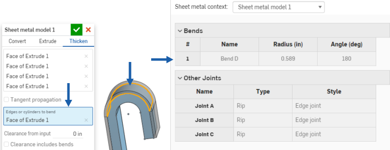
這樣會使得所選的一或多個弧被建立為彎折 (而非相切的接合),並列於彎折表格中,但半徑會是反灰的。這是因為弧在草圖中已有半徑,所以您無法在彎折表格中編輯半徑。
僅能將可用的特徵某些功能加入到使用中鈑金模型中 (例如,擠出 > 移除、移動面、布林運算與鑽孔)。所有的特徵都會出現在「特徵」清單、圖形區域中模型、鈑金表格與展開圖樣中。例如,您可以「擠出 > 移除」一個草圖來在使用中鈑金模型中建立一個開口。所產生的開口側邊會始終與其所貫穿的牆面垂直。
其他可修改模型的擠出選項像是加入或相交是無法使用的,在使用 [完成鈑金模型] 工具來將模型停用之後則可使用這些選項。
請注意,用來修改已停用鈑金模型的之後特徵對零件的作用就像在非鈑金零件上的特徵一樣,並不會影響展開圖樣或表格值。
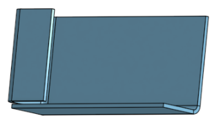
如果需要,可使用圓角與倒角來柔化鈑金的邊緣。請注意,必須選擇鈑金上明確轉角的邊線而不是相鄰的邊線。同時請注意,目前無法在鈑金上使用進階的圓角與倒角特徵 (例如,圓錐圓角)。
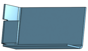
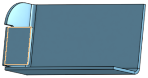
雖然有圓角或倒角,Onshape 會維持原始的建構邊線,並為之後的特徵使用該原始建構邊線。例如,若是在圓角邊線上建立凸緣,會忽略圓角並沿著原始的邊線建立凸緣。如果需要,您可以使用「移動面」工具來將凸緣的邊線移回至圓角的邊線上。
在轉角上產生圓角:
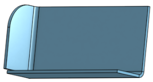
建立凸緣:
使用「移動面」來移動凸緣的邊線:
重新圓化轉角:
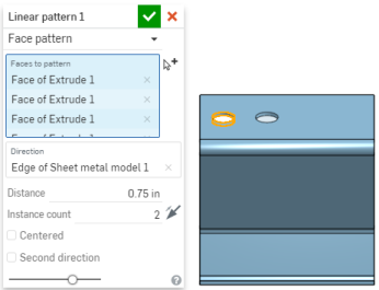
您可以使用複製排列工具 (線性複製排列、環狀複製排列與曲線複製排列) 中的「面」參數,或是使用鏡射鈑金面與凸緣來複製排列鈑金面與凸緣。如正常方式一般使用工具,只要確定選擇「面」做為複製排列類型,或在鏡射時選擇面即可:
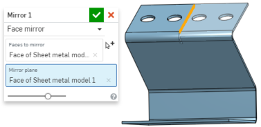
當鈑金模型啟用時 (在建立或編輯鈑金的過程中),其他可用的工具包括:
-
 凸緣 - 為每條所選的邊線建立牆面,使用彎折來連接所選的邊線。
 -
 摺邊 - 在現有的鈑金零件上為所選取的邊線/面建立摺邊。
 -
 薄板頁 - 將一個薄板頁加入至鈑金凸緣中。
 -
 Bend - Bend a sheet metal model along a reference line, with additional bend control options.
 -
 Form - Create form features on existing sheet metal models. Forms can be selected from the current document, other documents, or a predefined library of sheet metal forms.
 -
 Loft - Create sheet metal models that connect two profiles.
 -
 製作接合 - 將兩個牆面的相交處轉換為一個接合特徵,可以是一個彎折 (以圓柱幾何接合牆面),或是一個裂口 (兩個牆之間的小間隙)。
 -
 轉角 - 修改轉角類型與止裂比例。
 -
 彎折止裂 - 修改彎折止裂 (在彎折結束與自由邊線交會處做出的小切除)、深度與止裂寬度。
 -
 Modify joint - Make changes to an existing joint, such as converting a bend to a rip. Currently available through the flat view table.
 -
 Corner break - Break the corner on existing sheet metal parts by applying a fillet or chamfer. Select a corner edge or vertex and specify corner break type and distance. It is recommended to use this feature after all flanges and joints of the Sheet metal model are finalized.
 -
 Sheet metal table and flat view - Open and close the Rip/Bend tables and the visualization of the sheet metal model flat pattern. Use this table to convert rips to bends and vice versa.
 -
 完成鈑金模型 - 關閉 (停用) 鈑金模型;建立特徵清單中的特徵。
封住現有的零件來建立鈑金模型:
- 在 Part Studio 中輕觸
 。
。 - 選擇鈑金操作的類型:轉換
- 選擇要封住的零件。
- 選擇要排除在操作之外的面。
- 選擇要用來定義彎折的邊線;未選取的邊線會變為裂口。
沒有選取至 「要彎折的邊線或圓柱」欄位中的弧或樣條會變為相切的接合,而不是彎折。
- Specify applicable options:
- Clearance from input - The relative offset between the sheet metal and the part selected to be enclosed by the sheet metal
- Clearance includes bends - Check this to include the bend within the clearance value
- Keep input parts - Keep the selected parts (enclosed by the sheet metal) or not
- Thickness - The thickness of the sheet metal
- Bend radius - The inside radius of the bends created
- Flip direction up - Reverses the orientation of the sheet metal model and flat view. This is useful when defining whether bends are up or down, relative to the model.
- 彎折計算 - 決定計算彎折的方式。選項有:
- K 係數 (預設) - 使用中立軸與材料厚度的比例。
- 彎折裕度 - 使用彎折相切點之間的中立線弧長。
- 彎折扣除 - 使用凸緣長度總合 (從邊線到頂端) 與初始展開長度間的差異。
會將在這裡選擇的彎折計算用為鈑金表格中的一個欄位。可以自訂每個彎折並可從表格中直接編輯。詳細資訊請參考鈑金表格與展開視圖。
- Default bend K Factor - The fraction of material thickness on which the neutral axis lies on a bend. (Default is 0.45.)
- Rolled K Factor - The fraction of material thickness on which the neutral axis lies on a section of rolled wall. (Default is 0.5.)
- Minimal gap - The smallest gap between the sheet metal edges defining a rip
- Corner relief type -
- Square - Sized
Flat view:
 3D view:
- Rectangle - Scaled
Flat view:
 3D view:
- Round - Sized
Flat view:
 3D view:
- Round - Scaled
Flat view:
 3D view:
- Closed
Flat view:
 3D view:
- Simple
Flat view:
 3D view:
- Square - Sized
- Corner relief scale - The scale of the corner opening (for Scaled openings), a value between 1.00 and 2.00.
- Corner relief width - The measurement of the width of the corner opening (for Sized openings), in default units or specified units.
- Bend relief type - The shape of the bend relief:
- Rectangle - Scaled

- Obround - Scaled

- Tear

- Bend relief depth scale - A value between 1.00 and 5.00. Once you enter a value it becomes the default across all documents.
A value of 1 results in an obround bend relief perfectly touching the bend and a rectangular bend relief matches the depth of the obround.
任何超過 1 的值會根據此公式:((深度比例 -1) * 彎折半徑)。
- Bend relief width scale - A value between 0.0625 and 2.00. The width of the bend relief is calculated via the formula: thickness * width scale. Once you enter a value it becomes the default across all documents.
- 輕觸
 來接受特徵;鈑金模型會列在「特徵」清單中。
 - 請於此時套用任何其他特定的鈑金特徵,請見下方說明。
- 如果您要繼續將非鈑金特徵加入零件中,請輕觸完成鈑金模型
 。
。

擠出草圖曲線來建立鈑金模型:
- 在 Part Studio 中輕觸
 。
。 - 選擇擠出的鈑金操作。
- 選擇要擠出的草圖曲線。
- 選擇終止類型:給定深度、成形至下一幾何、成形至面、成形至零件、成形至一頂點。
-
對稱 - 選擇這個選項,僅能在「給定深度」終止類型中使用。指定總距離,會相對於草圖平面在兩個方向上各以一半的距離擠出。
- 拖曳或設定深度。
- 設定鈑金的厚度。
- 設定彎折的內部半徑。
- 如果您要反轉鈑金模型的方位與展開視圖,請核取「反轉方向朝上」。
- 選擇彎折計算來決定如何計算彎折。選項有:
- K 係數 (預設) - 使用中立軸與材料厚度的比例。
- 彎折裕度 - 使用彎折相切點之間的中立線弧長。
- 彎折扣除 - 使用凸緣長度總合 (從邊線到頂端) 與初始展開長度間的差異。
-
指定 K 係數 - 中立軸所在處材料厚度的分數。
- 設定最小間隙 - 鈑金邊線間的最小間隙。
- 轉角止裂類型:
- 正方形 - 尺寸
展開視圖:
 3D 視圖:
- 矩形 - 縮放
展開視圖:
 3D 視圖:
- 圓形 - 尺寸
展開視圖:
 3D 視圖:
- 圓形 - 縮放
展開視圖:
 3D 視圖:
- 封閉
展開視圖:
 3D 視圖:
- 簡易
展開視圖:
 3D 視圖:
- 正方形 - 尺寸
- 轉角止裂比例 - 轉角開口的比例 (針對縮放的轉角),是一個介於 1.00 和 2.00 之間的值。
- 折彎止裂類型 - 折彎止裂的形狀:
- 矩形 - 縮放:

- 圓端 - 縮放:

- 撕裂:

- 折彎止裂深度比例 - 介於 1.00 與 2.00 之間
- 折彎止裂寬度比例 - 介於 0.0625 到 2.00 之間的值
- 輕觸
 來接受特徵;鈑金模型會列在「特徵」清單中。
 - 請於此時套用任何其他特定的鈑金特徵,請見下方說明。
- 如果您要繼續將非鈑金特徵加入零件中,請輕觸完成鈑金模型
 。
。
您可以決定是否要將弧擠出為彎折,不過在「擠出為彎折的弧」欄位啟用的情況下選擇弧。
這樣會使得所選的一或多個弧被建立為彎折 (而非相切的接合)。
藉由加厚面、曲面或草圖區域來建立鈑金模型:
- 在 Part Studio 中輕觸
 。
。 - 選擇鈑金操作的類型:加厚
- 選擇草圖區域、平坦曲面或零件的面。
- 選擇要用來建立彎折的邊線;未選取的邊線會變為裂口,在弧與樣條的狀況中則會變為相切的接合。
- 指定適用的選項:
- 來自輸入的餘隙 - 鈑金與選擇來被鈑金所封閉的零件間的相對偏移
- 餘隙包括彎折 - 核取來為彎折包含餘隙
- 厚度 - 鈑金的厚度
- 彎折半徑 - 所建立彎折的內部半徑
- 反轉方向朝上 - 反轉鈑金模型與展開視圖的方位。當定義彎折相對於模型是朝上還是朝下時是相當有用的。
- 彎折計算 - 決定計算彎折的方式。選項有:
- K 係數 (預設) - 使用中立軸與材料厚度的比例。
- 彎折裕度 - 使用彎折相切點之間的中立線弧長。
- 彎折扣除 - 使用凸緣長度總合 (從邊線到頂端) 與初始展開長度間的差異。
- 預設彎折 K 係數 - 中立軸所在處的材料厚度分數 (預設是 0.45)。
軋延 K 係數 - 中立軸在捲曲鈑金壁部分的材料厚度分數 (預設是 0.5)。
- 最小間隙 - 鈑金邊線間的最小間隙
- 轉角止裂類型 - 轉角止裂的形狀:
- 正方形 - 尺寸
展開視圖:
 3D 視圖:
- 矩形 - 縮放
展開視圖:
 3D 視圖:
- 圓形 - 尺寸
展開視圖:
 3D 視圖:
- 圓形 - 縮放
展開視圖:
 3D 視圖:
- 封閉
展開視圖:
 3D 視圖:
- 簡易
展開視圖:
 3D 視圖:
- 正方形 - 尺寸
- 轉角止裂比例 - 轉角開口的比例 (針對縮放的轉角),是一個介於 1.00 和 2.00 之間的值。
- 折彎止裂類型:
- 矩形:

- 圓端:

- 撕裂:

- 折彎止裂深度比例 - 介於 1.00 與 2.00 之間。
- 折彎止裂寬度比例 - 介於 0.0625 到 2.00 之間。
- 輕觸
 來接受特徵;鈑金模型會列在「特徵」清單中。
 - 請於此時套用任何其他特定的鈑金特徵,請見下方說明。
- 如果您要繼續將非鈑金特徵加入零件中,請輕觸完成鈑金模型
 。
。 - 輕觸
 來關閉鈑金模型特徵;「完成鈑金模型」特徵會列在「特徵」清單中。

您可以決定是否要將弧加厚為彎折,不過在「擠出為彎折的弧」欄位啟用的情況下選擇弧。
這樣會使得所選的一或多個弧被建立為彎折 (而非相切的接合)。
僅能將可用的特徵某些功能加入到使用中鈑金模型中 (例如,擠出 > 移除、移動面、布林運算與鑽孔)。所有的特徵都會出現在「特徵」清單、圖形區域中模型、鈑金表格與展開圖樣中。例如,您可以「擠出 > 移除」一個草圖來在使用中鈑金模型中建立一個開口。所產生的開口側邊會始終與其所貫穿的牆面垂直。
其他可修改模型的擠出選項像是加入或相交是無法使用的,在使用 [完成鈑金模型] 工具來將模型停用之後則可使用這些選項。
請注意,用來修改已停用鈑金模型的之後特徵對零件的作用就像在非鈑金零件上的特徵一樣,並不會影響展開圖樣或表格值。
如果需要,可使用圓角與倒角來柔化鈑金的邊緣。請注意,必須選擇鈑金上明確轉角的邊線而不是相鄰的邊線。同時請注意,目前無法在鈑金上使用進階的圓角與倒角特徵 (例如,圓錐圓角)。
雖然有圓角或倒角,Onshape 會維持原始的建構邊線,並為之後的特徵使用該原始建構邊線。例如,若是在圓角邊線上建立凸緣,會忽略圓角並沿著原始的邊線建立凸緣。如果需要,您可以使用「移動面」工具來將凸緣的邊線移回至圓角的邊線上。
在轉角上產生圓角:

建立凸緣:

使用「移動面」來移動凸緣的邊線:

重新圓化轉角:

您可以使用複製排列工具 (線性複製排列、環狀複製排列與曲線複製排列) 中的「面」參數,或是使用鏡射鈑金面與凸緣來複製排列鈑金面與凸緣。如正常方式一般使用工具,只要確定選擇「面」做為複製排列類型,或在鏡射時選擇面即可。
當鈑金模型啟用時 (在建立或編輯鈑金的過程中),其他可用的工具包括:
-
 凸緣 - 為每條所選的邊線建立牆面,使用彎折來連接所選的邊線。
 -
 摺邊 - 在現有的鈑金零件上為所選取的邊線/面建立摺邊。
 -
 薄板頁 - 將一個薄板頁加入至鈑金凸緣中。
 -
 Bend - Bend a sheet metal model along a reference line, with additional bend control options.
 -
 Form - Create form features on existing sheet metal models. Forms can be selected from the current document, other documents, or a predefined library of sheet metal forms.
 -
 Loft - Create sheet metal models that connect two profiles.
 -
 製作接合 - 將兩個牆面的相交處轉換為一個接合特徵,可以是一個彎折 (以圓柱幾何接合牆面),或是一個裂口 (兩個牆之間的小間隙)。
 -
 轉角 - 修改轉角類型與止裂比例。
 -
 彎折止裂 - 修改彎折止裂 (在彎折結束與自由邊線交會處做出的小切除)、深度與止裂寬度。
 -
 Modify joint - Make changes to an existing joint, such as converting a bend to a rip. Currently available through the flat view table.
 -
 Corner break - Break the corner on existing sheet metal parts by applying a fillet or chamfer. Select a corner edge or vertex and specify corner break type and distance. It is recommended to use this feature after all flanges and joints of the Sheet metal model are finalized.
 -
 Sheet metal table and flat view - Open and close the Rip/Bend tables and the visualization of the sheet metal model flat pattern. Use this table to convert rips to bends and vice versa.
 -
 完成鈑金模型 - 關閉 (停用) 鈑金模型;建立特徵清單中的特徵。
關於在「學習中心」的其他資源,請參照這個自我引導式的課程:Self-Guided Simultaneous Sheet Metal (需要有 Onshape 帳戶)。您也可用自己的步調跟著 Simultaneous Sheet Metal (需要有 Onshape 帳戶) 的課程操作。