![]()
使用鈑金表格來編輯現有鈑金模型的彎折、裂口與接合會在特徵清單中建立一個修改接合的特徵。可以用編輯其他特徵的相同方式來編輯這個特徵,在特徵項目上按右鍵來存取環境選單。
在特徵清單中
在將彎折轉換為裂口之後 (使用表格指令,請見上方的說明),會有一個修改接合的特徵出現在特徵清單中。您可以按右鍵然後編輯這個新的接合:
- 在「特徵」清單中的「修改接合」特徵上按右鍵,然後選擇編輯,或連按兩下「修改接合」特徵。「修改接合」特徵對話方塊開啟:
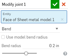
- 確認您要修改的接合邊線 (圖元) 或選擇一個不同的圖元。
- 選取下列的接合類型之一:
- 彎折 - 使用彎折中心線與半徑來在面/邊線間建立一條曲線。可為半徑保留模型屬性的預設,或取消核取該方塊並指定新的彎折半徑。
- 裂口 - 在兩個鈑金邊緣交會處建立面/邊線間的關聯。選擇「裂口」時,請選擇下列的裂口邊線類型之一:
- 邊線接合 - 同時延伸兩條邊線以在其內部邊線處相交。系統會使用來自鈑金模型特徵的最小間隙來建立兩個選取項目間的間隙。
- 對接 - 方向 1 - 將所選面/邊線的外邊線相互延伸直至相交。系統會使用來自鈑金模型特徵的最小間隙來建立兩個選取項目間的間隙。僅能為 90 度的接合使用這個選項。
- 對接 - 方向 2 - 類似於方向 1,但會反轉所選面/邊線的旋向性。
- 相切 - 如果一或多個邊線/面為圓形的,則在兩個選取的面/邊線之間建立相切邊線。
- 按一下
 來接受變更。
在「特徵」清單中的「修改接合」特徵會有此圖示 ![]() 。
。
當鈑金模型啟用時 (在建立或編輯鈑金的過程中),其他可用的工具包括:
-
 凸緣 - 為每條所選的邊線建立牆面,使用彎折來連接所選的邊線。
 -
 摺邊 - 在現有的鈑金零件上為所選取的邊線/面建立摺邊。
 -
 薄板頁 - 將一個薄板頁加入至鈑金凸緣中。
 -
 Bend - Bend a sheet metal model along a reference line, with additional bend control options.
 -
 Form - Create form features on existing sheet metal models. Forms can be selected from the current document, other documents, or a predefined library of sheet metal forms.
 -
 Loft - Create sheet metal models that connect two profiles.
 -
 製作接合 - 將兩個牆面的相交處轉換為一個接合特徵,可以是一個彎折 (以圓柱幾何接合牆面),或是一個裂口 (兩個牆之間的小間隙)。
 -
 轉角 - 修改轉角類型與止裂比例。
 -
 彎折止裂 - 修改彎折止裂 (在彎折結束與自由邊線交會處做出的小切除)、深度與止裂寬度。
 -
 Modify joint - Make changes to an existing joint, such as converting a bend to a rip. Currently available through the flat view table.
 -
 Corner break - Break the corner on existing sheet metal parts by applying a fillet or chamfer. Select a corner edge or vertex and specify corner break type and distance. It is recommended to use this feature after all flanges and joints of the Sheet metal model are finalized.
 -
 Sheet metal table and flat view - Open and close the Rip/Bend tables and the visualization of the sheet metal model flat pattern. Use this table to convert rips to bends and vice versa.
 -
 完成鈑金模型 - 關閉 (停用) 鈑金模型;建立特徵清單中的特徵。