 Forma in lamiera
![]()
![]()
![]()
Crea funzioni forma su modelli di lamiera esistenti. Le forme sono selezionabili nel documento corrente, in altri documenti o in una libreria predefinita di forme in lamiera.
Onshape è fornito con alcune forme standard nella libreria delle forme in lamiera Onshape. Se preferisci utilizzare una tua forma personalizzata, devi crearla prima di potervi accedere nella finestra di dialogo della funzione Forma. Per ulteriori informazioni, vedi Creare una forma.
Prima di aggiungere una funzione Forma, assicurati di avere un modello lamiera già creato in un Part Studio.
- Nel Part Studio in cui si trova il modello lamiera, fai clic sull'icona Forma (
 ) nella barra degli strumenti Funzione.
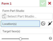
- Fai clic sul campo Seleziona Part Studio per aprire la finestra di dialogo Seleziona Part Studio:
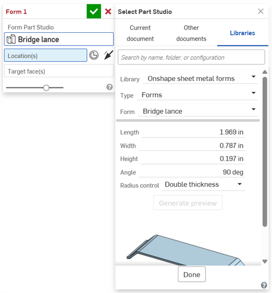
Seleziona un'opzione tra Documento corrente, Altri documenti o Librerie (dove è possibile selezionare la libreria delle forme lamiera Onshape o le librerie delle forme utente o Enterprise/azienda).
Seleziona Libreria, Tipo (il documento in cui è creata la forma) e Forma (il Part Studio in cui è creata la forma). Puoi anche utilizzare la barra di ricerca secondo necessità.
Se nel documento è presente una sola forma in un Part Studio, il campo Tipo non è visualizzato.
Se sono disponibili variabili di configurazione aggiuntive per il modulo, inserisci i relativi valori secondo necessità. In questo esempio della lancia ponte, per la forma sono disponibili le variabili Lunghezza, Larghezza, Altezza e Angolo.
Fai clic su Fine per aggiungere la forma.
- Seleziona laPosizione della foma selezionando nello schizzo vertici, punti o mate connector espliciti. Puoi anche fare clic sull'icona mate connector (
 ) e passare il cursore del mouse sul modello per selezionare i mate connector impliciti.
- Se necessario, fai clic sulla freccia della direzione opposta (
 ) per invertire la forma nella direzione opposta sulla faccia di destinazione.
 - Se non è già selezionata, seleziona laFaccia di destinazioneo le facce di destinazione della lamiera su cui posizionare la forma.
- Fai clic sul segno di spunta (
 ) per accettare la nuova funzione Forma.
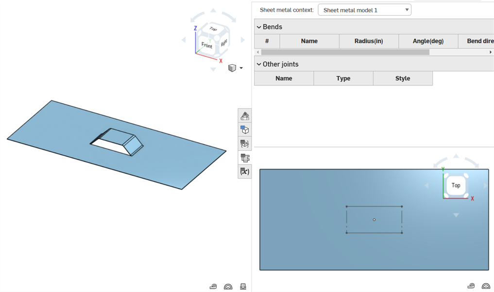
La forma è aggiunta al modello lamiera e alla ripetizione piatta:
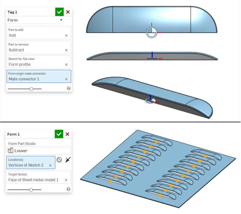
La forma grafica a persiana riportata di seguito mostra le viste superiore, laterale e isometrica della forma con la corrispondente funzione Tag (in alto). Questa forma è quindi utilizzata in una funzione Form e applicata ai punti dello schizzo sulla faccia di un modello in lamiera (in basso).
-
La funzione Tag utilizza la parte blu Aggiungi parte per aggiungerla al modello lamiera e la parte grigia Sottrai per rimuoverla dal modello lamiera.
-
Il posizionamento del mate connector fa passare la parte Sottrai attraverso la lamiera e contemporaneamente collega la parte Aggiungi alla lamiera.
-
La Forma mate connector di origine(Mate connector 1) della funzione Tag della forma determina l'origine della forma. Quando questa forma è posizionata sui vertici dello schizzo (Vertici dello schizzo 2) sulla faccia della lamiera (Faccia del modello lamiera 1), il mate connector della forma si allinea con i vertici dello schizzo della lamiera.
-
In alternativa, è possibile utilizzare un mate connector esplicito per allineare la forma al modello lamiera. Nell'esempio seguente, un mate connector (Mate connector 2) è utilizzato per la Posizione della funzione dellaForma anziché i vertici dello schizzo. L'asse secondario del mate connector è ruotato di 180 gradi e sia il Mate connector che le funzioni della Forma sono ripetute per creare lo stesso modello di cui sopra, ma con le persiane ruotate.

-
-
Le forme non possono toccare o inserirsi nei bordi di pareti laterali, lamiera calandrata, fessurazioni, spigoli chiusi o angoli della lamiera.
-
Le interruzioni spigolo non funzionano sui bordi di funzione di forma. Si consiglia di modellarli durante la creazione della forma personalizzata.
-
Quando si esporta la ripetizione piatta lamiera come file DXF/DWG, è possibile includere o escludere i contorni delle funzioni e dei segni centrali della forma. Vedi Esportare file DXF/DWG di ripetizione piatta.
-
L'inserimento di una ripetizione piatta in un disegno consente anche l'inserimento delle relative funzioni della forma, ad esempio il contorno e i punti centrali. Vedi Vista a ripetizione piatta.
-
Se si attiva la visibilità della funzione Forma nell'elenco funzioni, si attiva la visibilità dello schizzo nella Vista piatta lamiera (se uno schizzo è associato al modulo sottostante nella relativa funzione Tag:

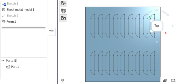
Schizzo del modulo visibile sulla vista piatta in lamiera
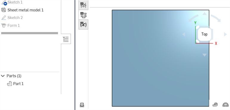
Schizzo del modulo nascosto sulla vista piatta in lamiera
Quando un modello di lamiera è attivo (durante la creazione o la modifica), sono disponibili strumenti aggiuntivi:
-
 flangia - Crea un muro per ogni bordo selezionato, collegato allo spigolo selezionato con una piega.
 -
 Orlo: crea un orlo per ogni bordo o faccia selezionati, su una lamiera esistente.
 -
 Tab - Aggiungere una linguetta a una flangia in lamiera.
 -
 Curva - Piegate un modello in lamiera lungo una linea di riferimento, con opzioni di controllo della piegatura aggiuntive.
 -
 Forma: crea funzioni forma su modelli di lamiera esistenti. Le forme sono selezionabili nel documento corrente, in altri documenti o in una libreria predefinita di forme in lamiera.
 -
 Crea un giunto - Convertite l'intersezione di due pareti in una caratteristica di giunzione, una piegatura (pareti unite da una geometria cilindrica) o uno strappo (piccolo spazio tra due pareti).
 -
 Angolo - Modificate il tipo di angolo e la scala di rilievo.
 -
 Rilievo di pieg - Modificare un rilievo di piegatura (il piccolo taglio eseguito nel punto in cui l'estremità della piega incontra lo spigolo libero), la profondità e la larghezza del rilievo.
 -
 Modificare il giunto - Apporta modifiche a un giunto esistente, ad esempio convertendo una piegatura in uno strappo. Attualmente disponibile nella tabella di visualizzazione piatta.
 -
 Interruzione spigolo: interrompe lo spigolo sulle parti in lamiera esistenti applicando un raccordo o uno smusso. Seleziona un bordo o vertice d'angolo e specifica il tipo e la distanza di interruzione dello spigolo. Consigliamo di utilizzare questa funzione dopo aver completato tutte le flange e gli spigoli chiusi del modello lamiera.
 -
 Tavolo in lamiera e vista piana - Aprire e chiudere le tabelle Rip/Bend e la visualizzazione dello schema piatto del modello in lamiera. Utilizzate questa tabella per convertire gli strappi in piegature e viceversa.
 -
 Disattiva modello lamiera: chiude (disattiva) il modello lamiera; crea una funzione nell'elenco funzioni.
Il supporto iOS e Android per la funzione Forma in lamiera è limitato alla visualizzazione delle forme create nella piattaforma desktop (browser).
Quando un modello di lamiera è attivo (durante la creazione o la modifica), sono disponibili strumenti aggiuntivi:
-
 flangia - Crea un muro per ogni bordo selezionato, collegato allo spigolo selezionato con una piega.
 -
 Tab - Aggiungere una linguetta a una flangia in lamiera.
 -
 Crea un giunto - Convertite l'intersezione di due pareti in una caratteristica di giunzione, una piegatura (pareti unite da una geometria cilindrica) o uno strappo (piccolo spazio tra due pareti).
 -
 Angolo - Modificate il tipo di angolo e la scala di rilievo.
 -
 Rilievo di pieg - Modificare un rilievo di piegatura (il piccolo taglio eseguito nel punto in cui l'estremità della piega incontra lo spigolo libero), la profondità e la larghezza del rilievo.
 -
 Interruzione spigolo: interrompe lo spigolo sulle parti in lamiera esistenti applicando un raccordo o uno smusso. Seleziona un bordo o vertice d'angolo e specifica il tipo e la distanza di interruzione dello spigolo. Consigliamo di utilizzare questa funzione dopo aver completato tutte le flange e gli spigoli chiusi del modello lamiera.
 -
 Disattiva modello lamiera: chiude (disattiva) il modello lamiera; crea una funzione nell'elenco funzioni.
Le librerie delle forme sono cartelle speciali che contengono forme. Si tratta di parti nei Part Studio che sono utilizzate come modelli per aggiungere o rimuovere elementi in modelli lamiera. Ogni Enterprise/azienda può disporre di una libreria delle forme di proprietà di un amministratore e può disporre di autorizzazioni di condivisione Enterprise/azienda in modo che tutti i membri dell'Enterprise/azienda possano accedere e utilizzare le forme nella cartella designata. Ogni singolo utente può inoltre configurare una libreria delle forme per il proprio uso personale. Non sono richieste autorizzazioni speciali per questa cartella. Questa libreria delle forme personale è accessibile e utilizzabile dal singolo utente.
Onshape fornisce contenuti standard per i moduli in lamiera nella libreria forme lamiera Onshape . Per ulteriori informazioni, vedi Libreria forme lamiera Onshape.
-
Le parti sono create e archiviate nei Part Studio. I documenti contenenti tali Part Studio sono quindi salvati in cartelle Onshape. A seconda di come desideri configurare e organizzare la tua libreria, crea una cartella nella pagina dei documenti (Crea > Cartella). Le librerie Enterprise/azienda vanno create nella cartella radice.
-
Se si tratta di una libreria Enterprise/aziendale, dalla pagina dei documenti:
-
Fai clic sull'icona Condividi
 nella cartella principale della gerarchia per aprire la finestra di dialogo delle impostazioni di condivisione:
-
Seleziona la scheda Team.
-
Cerca e aggiungi il team Tutti gli utenti Enterprise/dell'azienda.
-
Seleziona le caselle di controllo Collega documento e Condividi.
-
Fai clic sul pulsante Condividi:
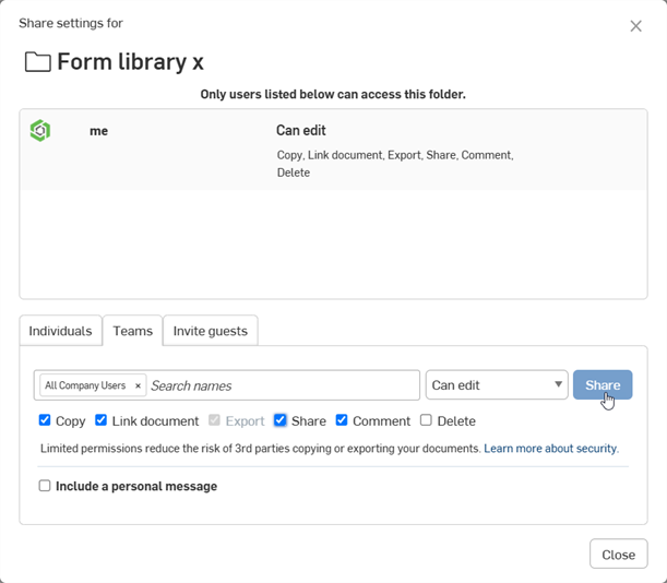
-
Fai clic sul pulsante Chiudi.
-
-
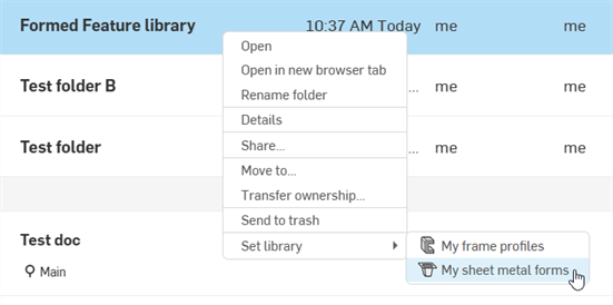
Nella pagina dei documenti, fai clic con il pulsante destro del mouse sulla cartella della forma e seleziona Imposta libreria > La mia libreria forme lamiera. Quando la libreria è configurata per la prima volta, l'icona della cartella cambia per indicare che si tratta di una libreria delle forme (
 ):
):
Non è necessario che le forme siano presenti in una libreria delle forme. È possibile creare una forma nello stesso documento del modello lamiera o in qualsiasi altro documento esterno alla libreria delle forme.
Una parte forma deve soddisfare le seguenti 2 condizioni:
-
Il Part Studio che contiene la parte deve avere una variabile di configurazione denominata spessore e il relativo Tipo deve essere impostato su Lunghezza.
-
Le parti della forma devono essere contrassegnate da tag.
È possibile disporre di una sola funzione di tag di modulo valida per ciascun Part Studio. Crea un modulo per ciascun Part Studio.
È inoltre necessario creare anche una versione documento se si fa riferimento esternamente alla forma da un altro documento.
Effettuare le seguenti operazioni per creare un documento della forma:
-
Se stai creando il modulo in una cartella della libreria delle forme utente o Enterprise/azienda, vai a tale cartella e fai clic su Crea > Documento . In alternativa puoi anche aprire il documento in cui desideri creare la forma e inserire una nuova scheda Part Studio.
-
Nella scheda Part Studio del documento crea una o più parti che definiscono la forma. Può trattarsi di parti che sono aggiunte o rimosse dalla lamiera (o entrambe le cose).
-
Crea una variabile di configurazione con il seguente formato:
-
Nome = spessore
-
Tipo = Lunghezza
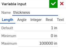
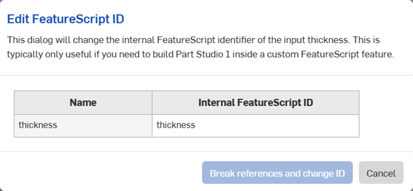
Lo spessoredell'ID FeatureScript è utilizzato per determinare lo spessore della forma dallo spessore della funzione modello lamiera. Per ulteriori informazioni, vedi Modificare configurazioni e tabelle.
-
-
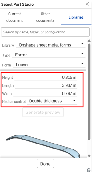
(Facoltativo) Utilizza variabili di configurazione aggiuntive durante la creazione della forma. Quando il modulo è selezionato tramite la finestra di dialogo Seleziona Part Studio della funzione Forma, queste variabili sn visualizzate come opzioni di dati di configurazione sotto la forma:
-
Crea una funzione Tag e contrassegna con tag le parti.
-
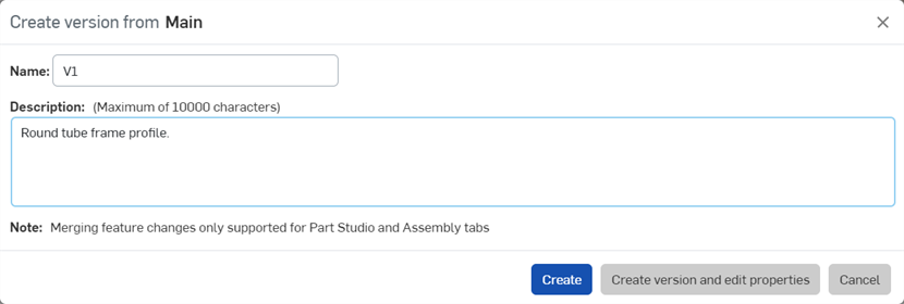
Fai clic su Crea versione nel pannello Documento. Inserisci un nome di versione e una descrizione opzionale, quindi fai clic sul pulsante Crea:
-
Se il documento del modulo esiste in una libreria delle forme utente o azienda/Enterprise, aggiorna la libreria delle forme.
Consulta la sezione precedente sui singoli passaggi per informazioni su come aggiungere questa forma al tuo modello lamiera.
Nella pagina dei documenti fai clic con il pulsante destro del mouse sulla cartella della libreria dele forme e seleziona Libreria forme lamiera > Disattiva la mia libreria (visualizzata qui di seguito). Ciò rimuove la designazione della cartella come libreria utente o libreria Enterprise/azienda, ma non elimina la cartella o il suo contenuto. La cartella assume l'aspetto di un'icona standard per indicare che si tratta di una cartella standard (![]() ).
).
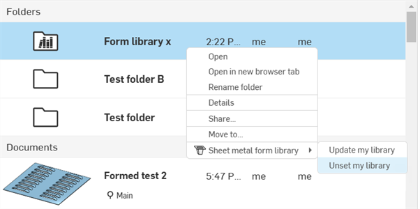
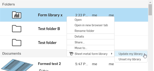
Se si apportano modifiche a un documento della forma all'interno di una cartella della libreria delle forme, la cartella deve essere aggiornata per consentire la propagazione delle nuove modifiche a tutte le funzioni della forma che fanno riferimento alla forma stessa.
Nella pagina dei documenti, fai clic con il pulsante destro del mouse sulla cartella della libreria delle forme e seleziona Libreria delle forme lamiera > Aggiorna la mia libreria:
Se una forma è aggiornata nella libreria delle forme, tutti i modelli esistenti che fanno riferimento a tale forma utilizzano ancora la forma precedente. Per aggiornare la forma:
-
Apri il documento del modello lamiera che utilizza la forma.
-
Fai doppio clic sulla funzione Forma nell'elenco funzioni.
-
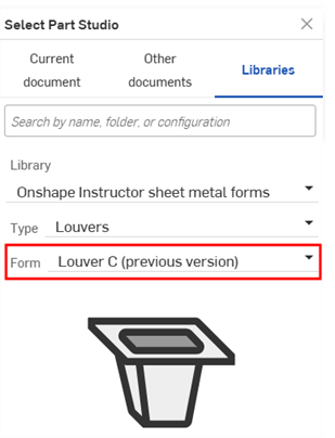
Fai clic sul campo Part Studio Forma (Persiana C nell'immagine seguente) per aprire la finestra di dialogo Seleziona Part Studio.
-
È visualizzata l'etichetta della Forma (versione precedente) e la miniatura generica del modulo, entrambe indicanti che il modello utilizza una versione precedente della forma. Fai clic sul menu a discesa Forma per aprire il menu di selezione:
-
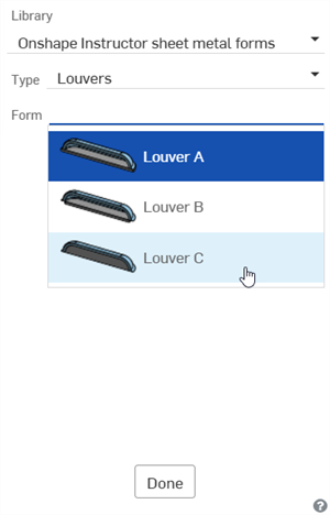
Seleziona la forma aggiornata nell'elenco e fai clic su Fine:
Per aggiungere un altro livello cartella:
-
Vai alla pagina dei documenti e naviga nella cartella a cui desideri aggiungere un nuovo livello di cartella (in questo esempio sarà aggiunta una cartella di quarto livello). Quindi crea una nuova cartella:
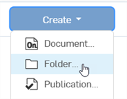
-
Nella finestra di dialogo Nuova cartella, indica il Nome cartella e fai clic su Crea.
-
Nella pagina dei documenti, seleziona la cartella e fai clic sull'icona Proprietà (
 ) per aprire le proprietà della cartella nel pannello laterale destro (vedi l'immagine sotto).
 -
Inserisci un'etichetta per la cartella nel campo Etichetta libreria. Utilizza i pulsanti Annulla (
 ) e Ripeti (
 ) per rimuovere o riscrivere il testo in questo campo.
 -
Fai clic su Applica.
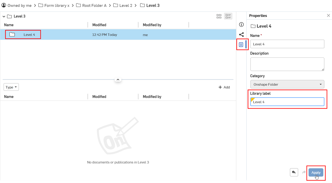
-
Aggiungi alla cartella un documento per la forma.
-
Vai alla cartella principale della libreria dei profili forma. Fai clic con il pulsante destro del mouse e seleziona Libreria dei profili forma > Aggiorna la mia libreria:
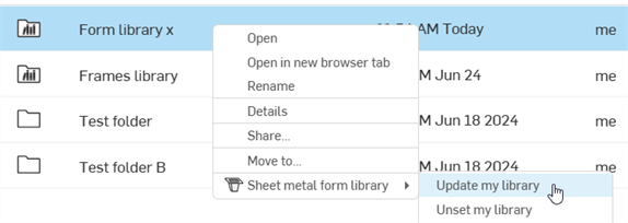
-
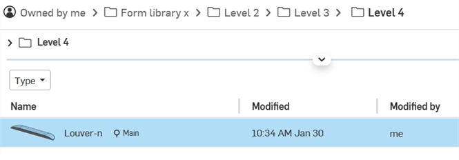
Apri un documento, fai clic sull'icona della funzione Forma e apri la finestra di dialogo Seleziona Part Studio. È ora presente un quarto livello che visualizza la forma:
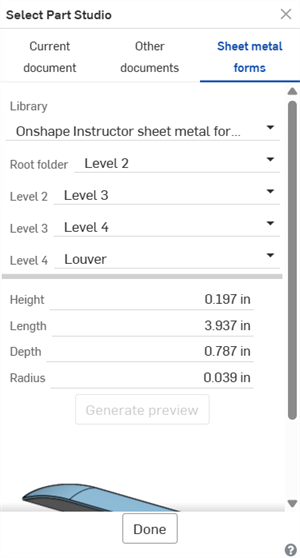
La finestra di dialogo Seleziona Part Studio mostra un quarto livello di cartella con la forma
È necessario che sia presente almeno un documento forma nell'ultima cartella dell'albero delle cartelle.
Note
-
Per le cartelle della libreria aziendale/Enterprise, poiché le Etichette della libreria sono ereditate dalle categorie Documento Onshape e Cartella Onshape, se rimuovi queste categorie, il campo Etichetta libreria non è più visibile o utilizzabile. Se queste categorie sono state rimosse in precedenza, aggiungile utilizzando il menu a discesa Trova e aggiungi categorie principali.

-
Se hai non più di 2 cartelle, le cartelle non richiedono etichette. Sono automaticamente etichettate come Tipo e Forma, in sequenza.
-
Se nello stesso documento sono presenti più forme (ciascuna nel relativo Part Studio), il documento deve avere anche una proprietà Etichetta libreria.

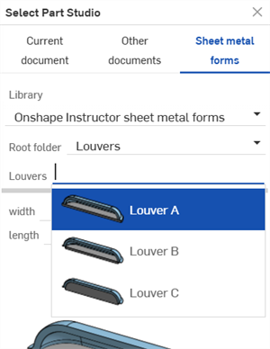
Più forme Persiana nello stesso documento
-
È necessario disporre di almeno un documento forma nell'ultima cartella dell'albero delle cartelle.
-
Se hai più di 3 cartelle, è necessario applicare etichette a tutte le cartelle. In caso contrario, durante l'aggiornamento della libreria è visualizzato il seguente messaggio:

-
È possibile aggiungere fino a 10 livelli di cartella principale (inclusa la cartella radice).
-
È possibile ramificare le cartelle da uno qualsiasi dei 10 livelli di cartelle principali. Ad esempio, nella quarta cartella, è possibile creare un numero qualsiasi di cartelle e ciascuna di esse può contenere 10 livelli di cartella.
-
Le forme non devono necessariamente esistere in una libreria delle forme. È possibile utilizzare qualsiasi parte di qualsiasi Part Studio purché sia un documento forma valido e soddisfi i requisiti dei documenti forma.
-
Non è possibile eliminare le cartelle delle librerie delle forme. Per eliminare una cartella, devi prima disattivarla.
-
Le autorizzazioni di condivisione per le cartelle della libreria delle forme non sono modificabili. Prima di tutto disattiva la cartella. Quindi modifica le autorizzazioni di condivisione della cartella.
-
Crea diversi Part Studio, ognuno con una forma e tutti contenuti in un unico documento. Se in un documento sono presenti più forme, la finestra di dialogo Seleziona parte Studio visualizza un nuovo campo Tipo che mostra il nome del documento e il menu a discesa Forma, in cui è selezionato Part Studio:
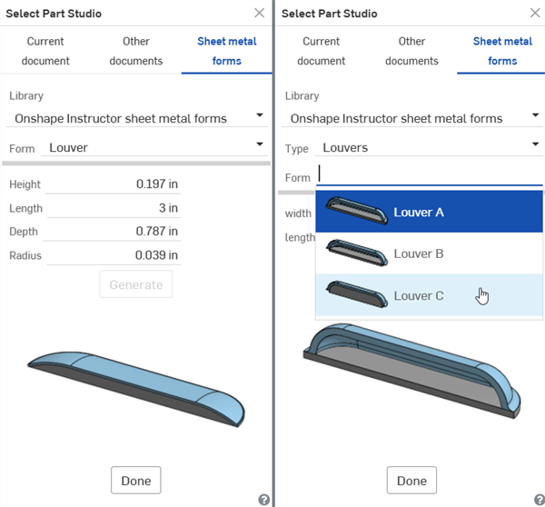
1 forma in 1 Part Studio in un documento (a sinistra); più forme in più Part Studio in un documento (a destra)