 Tag
Tag
![]()
Assegna alle entità del profilo di schizzo un tag utilizzabile nelle cornici o nelle parti che potresti volere aggiungere o rimuovere dalle forme in lamiera. Seleziona la geometria, definisci l'orientamento e aggiungi le proprietà.
Onshape fornisce una libreria di profili strutturali standard integrati direttamente nella funzione Cornice. Tuttavia, a volte potrebbe essere necessario creare una libreria personalizzata di profili di frame. È molto facile creare e condividere profili personalizzati da utilizzare con la funzione Frames. Questo video illustra come eseguire questa operazione definendo una libreria di schizzi, configurando il profilo per diverse opzioni di dimensione e etichettando il profilo in modo che la tabella della distinta di taglio sia compilata con i segmenti e le proprietà dei segmenti.
Per creare una nuova libreria di profili, crea un nuovo documento Onshape. Organizza i profili in uno o più documenti della libreria. Inserisci il documento della libreria in una cartella alla radice della società o dell'Enterprise. Questa pratica semplifica la condivisione con altri utenti che devono utilizzare i profili.
Crea uno schizzo del profilo in un Part Studio. Crea un Part Studio unico per ogni schizzo del profilo. Durante lo schizzo, considera come desideri allineare il profilo. Se necessario, aggiungi punti di schizzo da utilizzare come punti di allineamento aggiuntivi. Definisci lo schizzo con dimensioni e relazioni. Utilizza le variabili per definire le dimensioni dello schizzo che intendi configurare per le diverse opzioni di dimensione del profilo. Le variabili facilitano l'identificazione dei valori critici del profilo. Rinomina il Part Studio e lo schizzo per descrivere il profilo. Il nome univoco consente agli utenti di comprendere più facilmente l'intenzione del tuo profilo. Quando selezioni il profilo, il nome del Part Studio è visualizzato al livello superiore della finestra di dialogo e il nome dello schizzo è visualizzato al di sotto.
Se il profilo è disponibile in diverse dimensioni con la stessa forma, configura le dimensioni dello schizzo o i valori variabili. Crea tabelle di configurazione utilizzando i dati di configurazione per ogni dimensione, quindi configura le dimensioni o le variabili, se utilizzate. Modifica lo schizzo, fai clic con il pulsante destro del mouse su ciascuna dimensione per guidare la configurazione e seleziona Configura dimensione. Se hai definito lo schizzo con variabili, modifica la variabile, facendo clic con il pulsante destro del mouse sul valore e selezionando Configura. Modifica i valori nella tabella di configurazione.
Avvia quindi una nuova funzione Tag e seleziona Cornice nel menu a discesa. La funzione Tag aggiunge proprietà al profilo, quindi quando è utilizzata in una funzione Cornice, la tabella della distinta di taglio mostra le intestazioni delle colonne come Standard e Descrizione e inserisce i valori per tali proprietà.
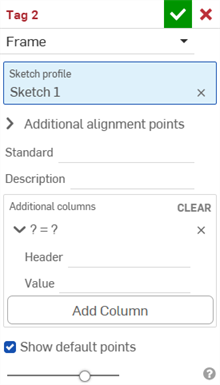
Seleziona il profilo dello schizzo. È possibile selezionarlo dall'area grafica o dall'elenco funzioni. Se sono necessari punti di allineamento aggiuntivi, espandi il campo di selezione e seleziona i punti nello schizzo da utilizzare come punti di allineamento, quindi inserisci stringhe numeriche o di testo per Standard e Descrizione. Se questi campi sono lasciati vuoti, la colonna non è aggiunta alla distinta di taglio quando è utilizzato il profilo oppure tale cella visualizza Non impostato se altri profili utilizzati nella struttura hanno l'intestazione di colonna definita. È possibile configurare sia i valori inseriti per Standard che per Descrizione. Fai clic con il pulsante destro del mouse sul campo nella finestra di dialogo Profilo tag e scegli Configura. Quindi modifica le celle nella tabella di configurazione.
Per fornire ulteriori proprietà per il profilo, fai clic su Aggiungi colonna e inserisci le informazioni sull'intestazione e sul valore. Ripeti l'operazione se necessario per aggiungere altre colonne alla tabella della distinta di taglio. Al termine, fai clic sul segno di spunta. Queste proprietà non sono configurabili. Fai clic sul pulsante Elimina (X) nella finestra di dialogo per rimuovere tutte le colonne.
Fai clic sul segno di spunta per accettare la funzione Tag. Il profilo è ora essere utilizzabile con le strutture contenute in questo documento. Avvia una nuova funzione Cornice in un altro Part Studio e fai clic sulla selezione del profilo dello schizzo nella finestra di dialogo. Nel documento corrente, seleziona il profilo. Regola la configurazione e fai clic su Genera per applicare i valori configurati, quindi seleziona il profilo dello schizzo.
Quando crei librerie di profili personalizzate, mantieni i profili in un documento diverso dai progetti che li utilizzano. In questo caso, assegna una versione al documento che contiene i profili una volta completata l'operazione. Da questo momento in poi, è possibile fare riferimento al profilo utilizzando documenti collegati. In questo esempio un documento diverso contiene i profili personalizzati. Fai clic su Altri documenti, passa al documento e seleziona il profilo dello schizzo.
Per consentire ad altri utenti di accedere ai profili personalizzati, è necessario condividere il documento o la cartella contenente i profili. Gli utenti che devono fare riferimento ai profili personalizzati nella funzione Cornici necessitano solo delle autorizzazioni di visualizzazione e collegamento. Gli utenti che aiutano a gestire i profili personalizzati necessitano delle autorizzazioni di modifica e collegamento. Usare i team per condividere è un ottimo modo per garantire l'accesso alle persone giuste e semplifica la gestione degli accessi. Quando si verificano cambiamenti di personale nell'organizzazione, è più facile gestire l'aggiunta o la rimozione di utenti in un team che individualmente.
Per assegnare un tag a un profilo che hai creato o modificato e utilizzare le informazioni contenute nella tabella della Distinta di taglio come colonne aggiuntive:
- Click the Tag icon (
 ) to open the Tag dialog:
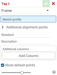
-
Seleziona Cornice ai fini del tag.
- Nel campo Profilo schizzo, seleziona lo schizzo nell'elenco funzioni che serve da schizzo per il profilo.
-
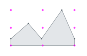
Per impostazione predefinita, l'opzione Mostra punti predefiniti è abilitata nella finestra di dialogo. Questo posiziona una griglia di allineamento a 9 punti di colore magenta sovrapposta al profilo dello schizzo. Deseleziona questa opzione per nascondere i punti di allineamento.
-
Nel campo Punti di allineamento aggiuntivi, seleziona qualsiasi altro punto dello schizzo che desideri utilizzare per l'allineamento.
- Nel campo Standard, inserisci il valore da visualizzare nella colonna Standard della tabella della Distinta di taglio.
- Nel campo Descrizione, inserisci una descrizione da visualizzare nella colonna Descrizione della tabella della Distinta di taglio.
- Per aggiungere altre colonne di informazioni per il profilo, fai clic su Aggiungi colonna:
-
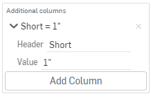
Nel campo Intestazione, inserisci il nome dell'intestazione della nuova colonna da visualizzare nella tabella della Distinta di taglio del profilo aggiuntivo e il valore:
-
Fai clic su Aggiungi colonna per aggiungere un'altra colonna/coppia di valori alla tabella della Distinta di taglio.
-
Fai clic sul segno di spunta (
 )
)
La procedura migliore consiste nell'assegnare un tag a un profilo, creare una versione e fare riferimento a tale versione del profilo nella cornice.
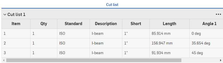
Osserva i nuovi valori nella colonna Descrizione e la colonna aggiuntiva "Breve" con i valori corrispondenti, sopra.
Le nuove informazioni del profilo compaiono nella tabella Distinta di taglio dopo l'utilizzo in una funzione Cornice, seguita da una funzione Tabella Distinta di taglio per creare una tabella. Fai clic su ![]() sul lato destro della finestra per aprire il pannello della tabella.
sul lato destro della finestra per aprire il pannello della tabella.
I tag di una forma indicano parti non in lamiera da utilizzare come funzioni forma per aggiungere o rimuovere materiale dal modello lamiera.
Per assegnare tag alle parti:
- Fai clic sull'icona Tag () per aprire la finestra di dialogo Tag:
-
Seleziona Forma ai fini del tag:
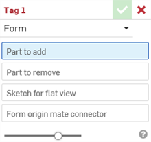
- Nel campo Parte da aggiungere, seleziona la parte nell'elenco Parti o nell'area grafica da aggiungere alla lamiera.
- Nel campo Parte da rimuovere, seleziona la parte nell'elenco Parti o nell'area grafica da cui sottrarre dalla lamiera.
- Seleziona lo schizzo per la vista piatta. Questo è lo schizzo utilizzato per la vista piatta del modello lamiera.
- Seleziona il mate connector origine forma. Questo determina la direzione in cui la forma è modellata nel modello lamiera. Passa il cursore del mouse sul modello dell'area grafica per selezionare un mate connector implicito o esplicito. Se non ne è selezionato nessuno, la funzione ne crea uno all'origine del Part Studio.
- Fai clic sul segno di spunta ( )
Non selezionare una parte in lamiera. Seleziona una parte geometrica standard.
Non selezionare una parte in lamiera. Seleziona una parte geometrica standard.
È possibile disporre di una sola funzione di tag di modulo valida per ciascun Part Studio. Crea un modulo per ciascun Part Studio.
-
 Cornice: crea una collezione di corpi sottoposti a sweep che condividono un profilo, disposti da punto a punto.
 -
 Rivestimento del telaio - Taglia i segmenti come gruppi ordinati.
 -
 tassello - Crea tasselli tra segmenti di telaio adiacenti.
 -
 Tappo terminale - Crea uno o più tappi terminali per i segmenti del telaio.
 -
 Lista di taglio - Crea una lista di taglio di tutti i segmenti di una cornice con le loro caratteristiche. Questa operazione crea anche una parte composita aperta per la collezione.
 -
Tag: contrassegna le entità del profilo dello schizzo da utilizzare nei telai o nelle parti per aggiungere o rimuovere elementi dalle forme in lamiera. Seleziona la geometria, definisci l'orientamento e aggiungi proprietà.