 Interruzione spigolo in lamiera
![]()
![]()
![]()
Interrompe lo spigolo sulle parti in lamiera esistenti applicando un raccordo o uno smusso. Seleziona un bordo o vertice d'angolo e specifica il tipo e la distanza di interruzione dello spigolo. Consigliamo di utilizzare questa funzione dopo aver completato tutte le flange e gli spigoli chiusi del modello lamiera.
Una delle fasi finali della progettazione in lamiera prevede l'interruzione degli spigoli vivi per prevenire lesioni personali o strappi. La funzione di Interruzione spigolo in lamiera di Onshape consente di aggiungere un raccordo o uno smusso a qualsiasi spigolo selezionato.
Riserva l'Interruzione spigolo per le funzioni finali di una parte in lamiera. Una volta applicata una funzione di interruzione spigolo, il Tipo e lo stile di Spigolo chiuso non sono più modificabili.
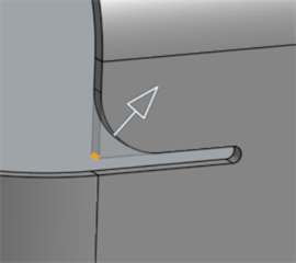
Le operazioni di interruzione spigolo si applicano a qualsiasi spigolo di una parte in lamiera, anche a quelli creati a causa di tagli di Scarico piega.
Avvia una nuova funzione Interruzione spigolo. Seleziona la scheda Raccordo o Smusso, quindi seleziona uno o più bordi con spigolo o vertici di una parte in lamiera. È possibile selezionare gli spigoli nello stato formato o appiattito.
Per un raccordo, seleziona Raggio o Larghezza per la misurazione. Inoltre, imposta l'opzione di controllo per il raccordo su Distanza, Conica o Curvatura.
Imposta il valore del raggio o della larghezza per dimensionare il raccordo. Per un raccordo a base conica, imposta il valore Rho. Per un raccordo basato sulla curvatura, imposta la Magnitudine.
Per un raccordo composto da due raggi miscelati tra loro, seleziona Asimmetrico e inserisci il Secondo raggio. Attiva o disattiva le frecce Inverti asimmetrico se necessario.
Sia Distanza che Conica hanno un'opzione per consentire il bordo a sfioro. La selezione di questa opzione consente alla funzione di raccordo di modificare i bordi sulla faccia creata dal raccordo, ottenendo una superficie liscia e continua. Se non selezioni questa opzione, Onshape conserva i bordi sulla faccia raccordata.
Per uno Smusso, imposta la misura su Offset o Tangente. Quindi seleziona un tipo di Smusso. Una distanza uguale estende lo smusso di una distanza uguale dal bordo in entrambe le direzioni. Due distanze estendono lo smusso per ogni valore di distanza immesso. Distanza e angolo estendono lo smusso di una distanza specificata in una direzione e di un angolo specificato nell'altra. Con entrambe queste opzioni, puoi attivare la freccia Direzione opposta per cambiare lato.
Per creare un'interruzione spigolo raccordata su un modello lamiera:
- In un Part Studio con un modello lamiera esistente, fai clic su Interruzione spigolo (
 ).
). 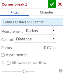
- Seleziona Raccordo per il tipo di interruzione spigolo.
- Seleziona un bordo o un vertice d'angolo sul modello lamiera nell'area grafica. È inoltre possibile selezionare un bordo o un vertice angolare nella sezione della vista piatta del modello lamiera e della vista piatta.
- Seleziona il tipo di misurazione:
- Raggio: specifica la misura radiale del raccordo.
- Larghezza: specifica la distanza tra le due estremità del raccordo (una larghezza costante).
- Seleziona un tipo di controllo:
- Distanza: il raccordo ha un bordo circolare con il valore raggio immesso. Onshape ricorda questo valore quando crea nuovi raccordi.
- Conica: il raccordo ha un bordo conico con il valore del raggio immesso ed eventualmente un valore rho per definire lo stile del raccordo:

Valori rho: 0,25 (sinistra; curva ellittica): 0,5 (centro; curva parabolica); 0,999 (destra; curva iperbolica (ingrandita))
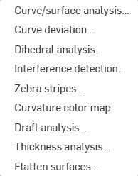
- Curvatura: il raccordo fa corrispondere la curvatura dei bordi circostanti con il valore di raggio che hai immesso manualmente e, se necessario, un valore di Magnitudine compreso tra 0 e 0,999 per modificare la tangenza. Attiva Strisce a zebra (dal menu Mostra strumenti di analisi) per vedere più chiaramente la tangenza:
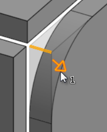
Quando inserisci un valore di raggio puoi anche utilizzare il manipolatore, come indicato nell'immagine sottostante da una freccia, per visualizzare il raccordo e avvicinarsi a un valore stimato:
Onshape ricorda la selezione per Tipo di misura e per il valore, e apre la finestra di dialogo con l'ultima opzione selezionata nelle operazioni successive.
- Seleziona Asimmetrico e inserisci un Secondo raggio per avere un diverso valore raggio del bordo del raccordo su un'estremità del bordo raccordato. Fai clic sulla freccia Inverti asimmetrico per utilizzare l'altra estremità del raccordo come secondo bordo del raccordo (asimmetrico).
- Per impostazione predefinita l'opzione Consenti bordo a sfioro è disabilitata. Seleziona l'opzione per consentire di eliminare i bordi tangenti dalla superficie del raccordo, se necessario. I bordi generati per impostazione predefinita vincolano in modo rigoroso la direzione del raccordo lungo i bordi del raccordo. Quando l'opzione Consenti bordo a sfioro è abilitata, il raccordo può modificare i bordi sulla faccia creata dal raccordo per creare una superficie liscia e continua. Quando l'opzione è deselezionata, i bordi della faccia raccordata sono preservati, dando luogo a una parte più scorrevole.
Fai clic sul menu a discesa Consenti bordo a sfioro per aprire un campo in cui puoi selezionare i bordi da conservare.
- Fai clic sul segno di spunta (
 ) per accettare la nuova funzione Interruzione spigolo.
Per creare un'interruzione spigolo smussata su un modello lamiera:
- In un Part Studio con un modello lamiera esistente, fai clic su Interruzione spigolo (
 ).
). 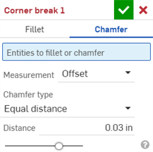
- Seleziona Smusso per il tipo di interruzione spigolo.
- Seleziona un bordo o un vertice d'angolo sul modello lamiera nell'area grafica. È inoltre possibile selezionare un bordo o un vertice angolare nella sezione della vista piatta del modello lamiera e della vista piatta.
- Seleziona il tipo di misurazione:
- Offset: imposta la distanza inserita nel campo Distanza dal bordo iniziale allo smusso. Questa opzione dipende dal bordo; il calcolo inizia dalla prima selezione e poi procede lungo la catena.
- Tangente: imposta la distanza inserita nel campo Distanza dall'intersezione della tangente delle due facce adiacenti allo smusso. Questa opzione NON dipende dal bordo.
- Seleziona un tipo di Smusso:
- Distanza uguale - Lo smusso si estenderà a una distanza uguale dal bordo in entrambe le direzioni.
- Due distanze - Chamfer estenderà distanze diverse in ciascuna direzione.
- Distanza e angolo - Lo smusso estenderà la distanza specificata in una direzione e dell'angolo specificato nell'altra.
Onshape ricorda la selezione per il tipo di smusso e apre la finestra di dialogo con l'ultima opzione selezionata nelle operazioni successive.
- Inserisci le distanze per lo smusso. Il valore predefinito di Onshape è 45 gradi per l'angolo, ma Onshape ricorda l'ultimo valore di distanza immesso per Distanza uguale e Distanza e smussi angolari.
- Se hai selezionato Due distanze o Distanza e angolo, fai clic sul pulsante freccia per invertire la direzione di tutti i bordi o specifica i singoli bordi da invertire nel campo Sovrascritture direzione.
- Fate clic sul segno di spunta (
 ) per accettare la nuova funzione Interruzione spigolo.
-
Dopo aver applicato una funzione di interruzione spigolo, tutti i seguenti elementi degli spigoli chiusi del modello Tipo (Fessurazione o Piega) e Stile (Spigolo chiuso bordo o Sormonto) non sono più modificabili nella Tabella lamiera e vista piatta. Consigliamo di aggiungere eventuali funzioni interruzione spigolo dopo aver completato tutte le modifiche alle flange e agli spigoli chiusi del modello lamiera.
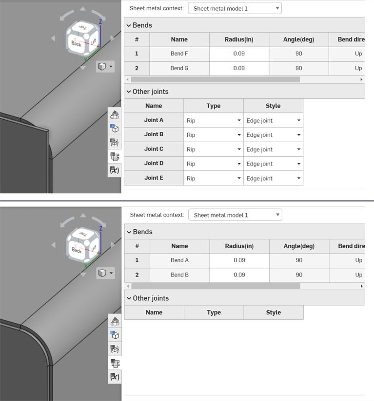
Prima dell'applicazione della funzione interruzione spigolo (in alto); dopo l'applicazione della funzione interruzione spigolo (in basso)
-
È possibile utilizzare Interruzione spigolo per applicare raccordi o smussi ai bordi e ai vertici dello Scarico piega, oltre agli spigoli:
-
Non è possibile aggiungere più raccordi, smussi o una combinazione di entrambi sugli spigoli utilizzando una singola funzione interruzione spigolo. Crea un'ulteriore funzione interruzione spigolo per aggiungere un raccordo o uno smusso aggiuntivo a qualsiasi vertice o bordo di una funzione interruzione spigolo già esistente:
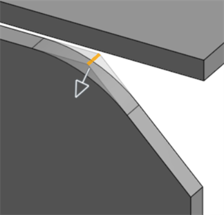
Raccordo applicato a un bordo smussato utilizzando una seconda funzione interruzione spigolo
Quando un modello di lamiera è attivo (durante la creazione o la modifica), sono disponibili strumenti aggiuntivi:
-
 flangia - Crea un muro per ogni bordo selezionato, collegato allo spigolo selezionato con una piega.
 -
 Orlo: crea un orlo per ogni bordo o faccia selezionati, su una lamiera esistente.
 -
 Tab - Aggiungere una linguetta a una flangia in lamiera.
 -
 Curva - Piegate un modello in lamiera lungo una linea di riferimento, con opzioni di controllo della piegatura aggiuntive.
 -
 Forma: crea funzioni forma su modelli di lamiera esistenti. Le forme sono selezionabili nel documento corrente, in altri documenti o in una libreria predefinita di forme in lamiera.
 -
 Loft - Create sheet metal models that connect two profiles.
 -
 Crea un giunto - Convertite l'intersezione di due pareti in una caratteristica di giunzione, una piegatura (pareti unite da una geometria cilindrica) o uno strappo (piccolo spazio tra due pareti).
 -
 Angolo - Modificate il tipo di angolo e la scala di rilievo.
 -
 Rilievo di pieg - Modificare un rilievo di piegatura (il piccolo taglio eseguito nel punto in cui l'estremità della piega incontra lo spigolo libero), la profondità e la larghezza del rilievo.
 -
 Modificare il giunto - Apporta modifiche a un giunto esistente, ad esempio convertendo una piegatura in uno strappo. Attualmente disponibile nella tabella di visualizzazione piatta.
 -
 Interruzione spigolo: interrompe lo spigolo sulle parti in lamiera esistenti applicando un raccordo o uno smusso. Seleziona un bordo o vertice d'angolo e specifica il tipo e la distanza di interruzione dello spigolo. Consigliamo di utilizzare questa funzione dopo aver completato tutte le flange e gli spigoli chiusi del modello lamiera.
 -
 Tavolo in lamiera e vista piana - Aprire e chiudere le tabelle Rip/Bend e la visualizzazione dello schema piatto del modello in lamiera. Utilizzate questa tabella per convertire gli strappi in piegature e viceversa.
 -
 Disattiva modello lamiera: chiude (disattiva) il modello lamiera; crea una funzione nell'elenco funzioni.
Per creare un'interruzione spigolo raccordata su un modello lamiera:
- In un Part Studio con un modello lamiera esistente, tocca Interruzione spigolo (
 ).
). 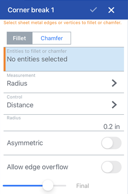
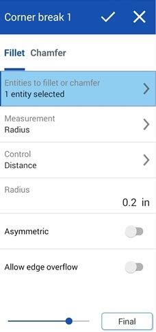
Interruzione spigolo: finestra di dialogo Raccordo per iOS (prima immagine visualizzata sopra) e Android (seconda immagine)
- Tocca Raccordo per il tipo di interruzione spigolo.
- Seleziona un bordo o un vertice d'angolo sul modello lamiera nell'area grafica.
- Seleziona il tipo di misurazione:
- Raggio: specifica la misura radiale del raccordo.
- Larghezza: specifica la distanza tra le due estremità del raccordo (una larghezza costante).
- Seleziona un tipo di controllo:
- Distanza: il raccordo ha un bordo circolare con il valore raggio immesso. Onshape ricorda questo valore quando crea nuovi raccordi.
- Conica: il raccordo ha un bordo conico con il valore del raggio immesso ed eventualmente un valore rho per definire lo stile del raccordo:

Rho values: 0.25 (left; elliptical curve); 0.5 (middle; parabolic curve); 0.999 (right; hyperbolic curve - zoomed in)
- Curvatura: il raccordo fa corrispondere la curvatura dei bordi circostanti con un valore di raggio immesso e, se necessario, un valore di magnitudine compreso tra 0 e 0,999 per regolare la tangenza.
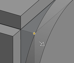
Quando inserisci un valore di raggio puoi anche utilizzare il manipolatore, come indicato nell'immagine sottostante da una freccia, per visualizzare il raccordo e avvicinarsi a un valore stimato:
- Attiva Asimmetrico e inserisci un Secondo raggio per avere un diverso valore raggio del bordo del raccordo su un'estremità del bordo raccordato. Attiva la freccia Inverti asimmetrico per utilizzare l'altra estremità del raccordo come secondo bordo del raccordo (asimmetrico).
- Per impostazione predefinita l'opzione Consenti bordo a sfioro è disattivata. Attiva questa opzione per consentire di rimuovere, figurativamente, i bordi tangenti dalla superficie del raccordo, se necessario. I bordi generati per impostazione predefinita vincolano in modo rigoroso la direzione del raccordo lungo i bordi del raccordo. Quando l'opzione Consenti bordo a sfioro è abilitata, il raccordo può modificare i bordi sulla faccia creata dal raccordo per creare una superficie liscia e continua. Quando l'opzione è disattivata, i bordi della faccia raccordata sono preservati, dando luogo a una parte più scorrevole.
Tocca il campo Bordi da mantenere e seleziona i bordi da mantenere nell'area grafica.
- Tocca il segno di spunta per accettare la nuova funzione interruzione spigolo.
Per creare un'interruzione spigolo smussata su un modello lamiera:
- In un Part Studio con un modello lamiera esistente, tocca Interruzione spigolo (
 ).
). 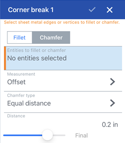
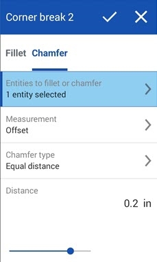
Interruzione spigolo: finestra di dialogo Smusso per iOS (prima immagine visualizzata sopra) e Android (seconda immagine)
- Tocca Smusso per il tipo di interruzione spigolo.
- Seleziona un bordo o un vertice d'angolo sul modello lamiera nell'area grafica.
- Seleziona il tipo di misurazione:
- Offset: imposta la distanza inserita nel campo Distanza dal bordo iniziale allo smusso. Questa opzione dipende dal bordo; il calcolo inizia dalla prima selezione e poi procede lungo la catena.
- Tangente: imposta la distanza inserita nel campo Distanza dall'intersezione della tangente delle due facce adiacenti allo smusso. Questa opzione NON dipende dal bordo.
- Seleziona un tipo di Smusso:
- Distanza uguale - Lo smusso si estenderà a una distanza uguale dal bordo in entrambe le direzioni.
- Due distanze - Chamfer estenderà distanze diverse in ciascuna direzione.
- Distanza e angolo - Lo smusso estenderà la distanza specificata in una direzione e dell'angolo specificato nell'altra.
- Inserisci le distanze per lo smusso. Il valore predefinito di Onshape è 45 gradi per l'angolo, ma Onshape ricorda l'ultimo valore di distanza immesso per Distanza uguale e Distanza e smussi angolari.
- Se hai selezionato Due distanze o Distanza e angolo, fai clic sul pulsante freccia per invertire la direzione di tutti i bordi o specifica i singoli bordi da invertire nel campo Sovrascritture direzione.
- Tocca il segno di spunta per accettare la nuova funzione interruzione spigolo.
-
Dopo aver applicato una funzione di interruzione spigolo, tutti i seguenti elementi degli spigoli chiusi del modello Tipo (Fessurazione o Piega) e Stile (Spigolo chiuso bordo o Sormonto) non sono più modificabili nella Tabella lamiera e vista piatta. Consigliamo di aggiungere eventuali funzioni interruzione spigolo dopo aver completato tutte le modifiche alle flange e agli spigoli chiusi del modello lamiera.
-
È possibile utilizzare Interruzione spigolo per applicare raccordi o smussi ai bordi e ai vertici dello Scarico piega, oltre agli spigoli:

-
Non è possibile aggiungere più raccordi, smussi o una combinazione di entrambi sugli spigoli utilizzando una singola funzione interruzione spigolo. Crea un'ulteriore funzione interruzione spigolo per aggiungere un raccordo o uno smusso aggiuntivo a qualsiasi vertice o bordo di una funzione interruzione spigolo già esistente:

Raccordo applicato a un bordo smussato utilizzando una seconda funzione interruzione spigolo
Quando un modello di lamiera è attivo (durante la creazione o la modifica), sono disponibili strumenti aggiuntivi:
-
 flangia - Crea un muro per ogni bordo selezionato, collegato allo spigolo selezionato con una piega.
 -
 Tab - Aggiungere una linguetta a una flangia in lamiera.
 -
 Crea un giunto - Convertite l'intersezione di due pareti in una caratteristica di giunzione, una piegatura (pareti unite da una geometria cilindrica) o uno strappo (piccolo spazio tra due pareti).
 -
 Angolo - Modificate il tipo di angolo e la scala di rilievo.
 -
 Rilievo di pieg - Modificare un rilievo di piegatura (il piccolo taglio eseguito nel punto in cui l'estremità della piega incontra lo spigolo libero), la profondità e la larghezza del rilievo.
 -
 Loft - View and modify sheet metal models that connect two profiles.
 -
 Interruzione spigolo: interrompe lo spigolo sulle parti in lamiera esistenti applicando un raccordo o uno smusso. Seleziona un bordo o vertice d'angolo e specifica il tipo e la distanza di interruzione dello spigolo. Consigliamo di utilizzare questa funzione dopo aver completato tutte le flange e gli spigoli chiusi del modello lamiera.
 -
 Disattiva modello lamiera: chiude (disattiva) il modello lamiera; crea una funzione nell'elenco funzioni.