 シートメタルコーナー切断
![]()
![]()
![]()
フィレットまたは面取りを適用して、既存のシートメタルパーツのコーナーを切断します。コーナーのエッジまたは頂点を選択し、コーナー切断のタイプと距離を指定します。このフィーチャーは、シートメタルモデルすべてのフランジとジョイントが完成してから使用することをお勧めします。
シートメタル設計の最後の手順の 1 つに、怪我や引っ掛かりを防ぐために鋭いコーナーを切断することが含まれます。Onshape のシートメタルコーナー切断フィーチャーは、選択した任意のコーナーにフィレットまたは面取りを追加することでこれを実現します。
シートメタルパーツの最終フィーチャーのために、コーナー切断をリザーブしておきます。[コーナー切断] フィーチャー適用すると、ジョイントタイプとスタイルは変更できません。
コーナー切断は、曲げリリーフの切れ込みによって作成されたコーナーも含め、シートメタルパーツのすべてのコーナーに適用されます。
新しい [コーナー切断] フィーチャーを開始します。[フィレット] タブまたは [面取り] タブを選択し、シートメタルパーツの 1 つまたは複数のコーナーのエッジまたは頂点を選択します。コーナーは、成形状態またはフラット化状態で選択できます。
フィレットの場合は、測定値として [半径] または [幅] を選択します。さらに、フィレットの制御オプションを [距離]、[円錐]、または [曲率] に設定します。
半径または幅の値を設定してフィレットの寸法を記入します。円錐形のフィレットの場合は、Rho 値を設定します。曲率ベースのフィレットの場合は、マグニチュードを設定します。
2 つの半径をブレンドして構成するフィレットの場合は、[非対称] にチェックを入れ、2 番目の半径を入力します。必要に応じて [非対称に反転] 矢印を切り替えます。
[距離] と [円錐] の両方に [エッジオーバーフローを許可] のオプションがあります。このオプションをオンにすると、フィレットフィーチャーはフィレットによって作成された面エッジを変更できるため、滑らかで連続的なサーフェスが得られます。このオプションをオフにすると、Onshape はフィレットされた面のエッジを保持します。
面取りの場合は、[測定] を [オフセット] または [接線] に設定します。次に、面取りタイプを選択します。[等距離] の場合は、エッジから両方向に等しい距離だけ面取りが延長されます。[2 つの距離] の場合は、入力した距離値ごとに面取りが延長されます。[距離と角度] の場合は、一方向に指定した距離だけ面取りが延長され、もう一方の方向には指定した角度だけ面取りが伸びます。どちらのオプションでも、[反対方向] の矢印を切り替えて逆向きにすることができます。
シートメタルモデルにフィレット付きコーナー切断を作成するには、次の操作を実行します。
- 既存のシートメタルモデルがある Part Studio で [コーナー切断] (
 ) をクリックします。
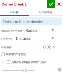
- コーナー切断のタイプとして [フィレット] を選択します。
- グラフィック領域でシートメタルモデルのコーナーエッジまたは頂点を選択します。シートメタルモデルと展開図の展開図のセクションでは、コーナーエッジまたは頂点を選択することもできます。
- 測定タイプを次のいずれかから選択します。
- 半径 - フィレットの半径方向の寸法を指定します。
- 幅 - フィレットの 2 つの端点間の距離 (一定の幅) を指定します。
- 制御タイプを選択します。
- 距離 - フィレットには半径の値が入力された円形エッジがあります。Onshape は、新しいフィレットを作成するときにこの値を記憶します。
- 円錐 - フィレットには、半径の値を入力した円錐のエッジと、必要に応じてフィレットのスタイルを定義する Rho 値があります。

Rho 値: 0.25 (左; 楕円曲線): 0.5 (中央; 放物線曲線); 0.999 (右; 双曲線曲線 - 拡大表示)
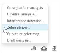
- 曲率 - フィレットは、周囲のエッジの曲率と、入力した半径の値および必要に応じて 0 ~ .999 の間のマグニチュード値を一致させ、接線を微調整します。ゼブラストライプを ([分析ツールを表示] メニューで) オンにして、接線をより明確に確認します。
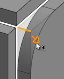
半径値を入力するときは、次の図に示す矢印で示されているドラッグマニピュレータを使用して、フィレットを視覚化し、推定値に近づけることもできます。
Onshape は測定タイプと値の選択を記憶するので、最後に使ったオプションが選択された状態でダイアログが開きます。
- [非対称] をオンにし、2 番目の半径を入力すると、フィレットしたエッジの一方の端のフィレットエッジの半径の値が変わります。[非対称] 矢印をクリックすると、フィレットのもう一方の端が 2 番目の (非対称) フィレットエッジとして使用されます。
- 既定では、[エッジオーバーフローを許可] は無効ですが、必要に応じて有効にすると、接線エッジをフィレットサーフェスから削除できます。既定で生成されるエッジは、フィレットエッジに沿ってフィレットの方向を厳密に拘束します。[エッジオーバーフローを許可] を有効にすると、フィレットによって作成された面のエッジを修正して、滑らかで連続したサーフェスを作成できます。このオプションをオフにすると、フィレット面のエッジが保持され、より自由に流れるパーツになります。
[エッジオーバーフローを許可] ドロップダウンをクリックすると、保持するエッジを選択できるフィールドが開きます。
- チェックマーク (
 ) をクリックして、新しいコーナー切断のフィーチャーを確定します。
シートメタルモデルに面取り付きコーナー切断を作成するには、次の操作を実行します。
- 既存のシートメタルモデルがある Part Studio で [コーナー切断] (
 ) をクリックします。
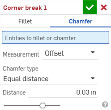
- コーナー切断のタイプとして [面取り] を選択します。
- グラフィック領域でシートメタルモデルのコーナーエッジまたは頂点を選択します。シートメタルモデルと展開図の展開図のセクションでは、コーナーエッジまたは頂点を選択することもできます。
- 測定タイプを次のいずれかから選択します。
- オフセット - 距離フィールドに入力された開始エッジから面取りまでの距離を設定します。このオプションはエッジに依存し、計算は最初の選択から始まり、チェーン全体に進んでいきます。
- 接線 - 距離フィールドに入力された隣接する 2 つの面の接線の交点から面取りまでの距離を設定します。このオプションはエッジに依存しません。
- 面取りのタイプを選択します。
- 等距離 - 面取りはエッジから両方向に等しい距離まで延長します。
- 2 つの距離 - 面取りは各方向に異なる距離まで延長します。
- 距離と角度 - 面取りは、一方向に指定された距離まで延長され、もう一方向は指定した角度だけ延長されます。
Onshape は面取りタイプの選択を記憶するので、最後に選択していたダイアログとそのオプションが後続の操作で開きます。
- 面取りの距離を入力します。Onshape の既定の角度は 45 度ですが、[等距離] および [距離と角度の面取り] に最後に入力された距離の値は記憶されます。
- [2 つの距離] または [距離と角度] を選択した場合は、矢印ボタンをクリックしてすべてのエッジの方向を反転するか、[方向のオーバーライド] フィールドで個々のエッジを指定して反転させます。
- チェックマーク (
 ) をクリックして、新しいコーナー切断のフィーチャーを確定します。
-
コーナー切断のフィーチャー適用すると、すべてのモデルジョイントのタイプ (リッピングまたは曲げ) とスタイル (エッジジョイントまたは開先溶接) はシートメタルテーブルと展開図で編集できなくなります。シートメタルモデルのフランジとジョイント編集をすべて完了した後に、コーナー切断のフィーチャーを追加することをお勧めします。
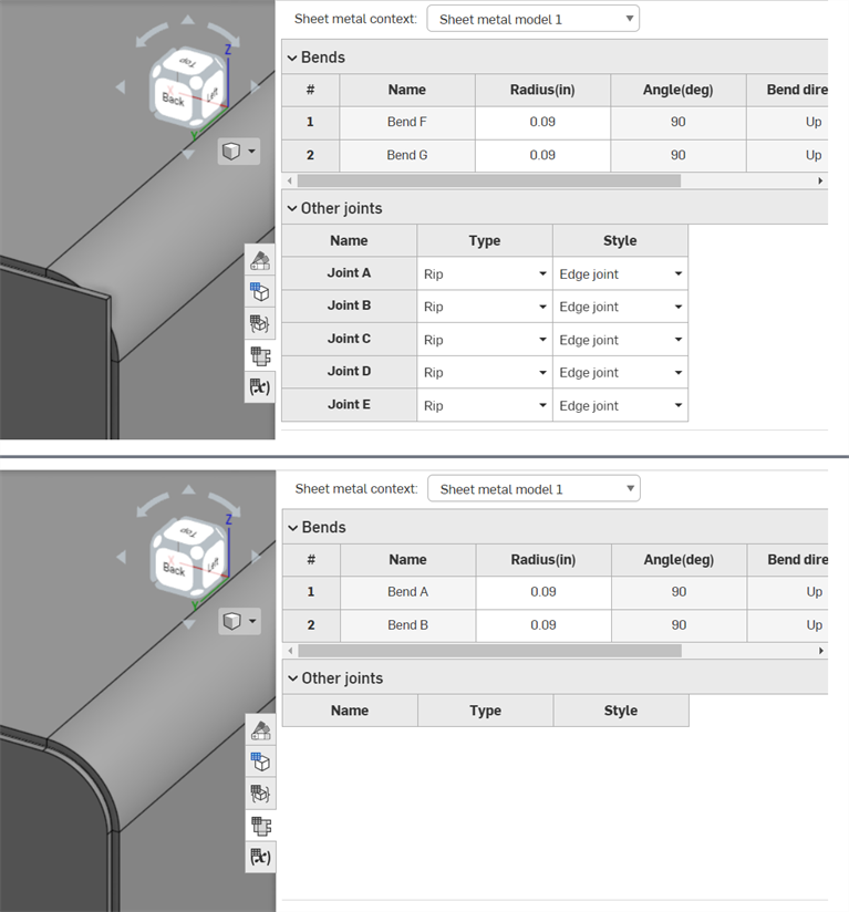
コーナー切断のフィーチャーを適用する前 (上)、コーナー切断のフィーチャーを適用した後 (下)
-
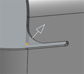
コーナー切断を使用すると、コーナーだけでなく、曲げリリーフのエッジや頂点にもフィレットや面取りを適用できます。
-
コーナー切断のフィーチャーを 1 つ使用して、複数のフィレット、面取り、または両方の組み合わせをコーナーに追加することはできません。コーナー切断のフィーチャーを追加して、既存のコーナー切断のフィーチャーの任意の頂点またはエッジにフィレットまたは面取りを追加します。
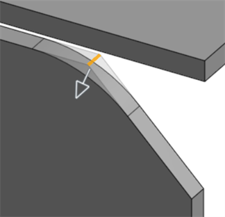
2 つ目のコーナー切断のフィーチャーを使用して面取りしたエッジにフィレットを適用
シートメタルモデルがアクティブの場合 (作成または編集中) は、次のツールを使用できます。
-
 フランジ - 選択したエッジごとに壁を作成し、選択したエッジに曲げを用いて接続します。
 -
 ヘム - 既存のシートメタルパーツ上に、選択したエッジまたは面ごとにヘムを作成します。
 -
 タブ - シートメタルフランジにタブを追加します。
 -
 曲げ - 追加の曲げ制御オプションを使用して、シートメタルモデルを基準線に沿って曲げます。
 -
 フォーム - 既存のシートメタルモデルにフォームフィーチャーを作成します。フォームは、現在のドキュメント、他のドキュメント、またはシートメタルフォームの事前定義済みライブラリから選択できます。
 -
 ジョイントを作成 - 2 つの壁の交差を、曲げ (円筒状のジオメトリで結合された壁) またはリップ (2 つの壁の間の小さなギャップ) のジョイントフィーチャーに変換します。
 -
 コーナー - コーナータイプとリリーフスケールを修正します。
 -
 曲げリリーフ - 曲げリリーフ (曲げの端がフリーエッジに接する部分に作られた小さなカット)、深度、およびリリーフ幅を修正します。
 -
 ジョイントを変更 - 曲げをリップに変換するなど、既存のジョイントを変更します。現在は、展開図テーブルで利用できます。
 -
 コーナー切断 - フィレットまたは面取りを適用して、既存のシートメタルパーツのコーナーを切断します。コーナーのエッジまたは頂点を選択し、コーナー切断のタイプと距離を指定します。このフィーチャーは、シートメタルモデルすべてのフランジとジョイントが完成してから使用することをお勧めします。
 -
 シートメタルテーブルと展開図 - リップ/曲げテーブルを開閉し、シートメタルモデルのフラットパターンを表示します。このテーブルを使用して、リップを曲げに、または曲げをリップに変換します。
 -
 シートメタルモデル仕上げ - シートメタルモデルを閉じ (非アクティブにする)、フィーチャーリストにフィーチャーを作成します。
シートメタルモデルにフィレット付きコーナー切断を作成するには、次の操作を実行します。
- 既存のシートメタルモデルがある Part Studio で [コーナー切断] (
 ) をタップします。
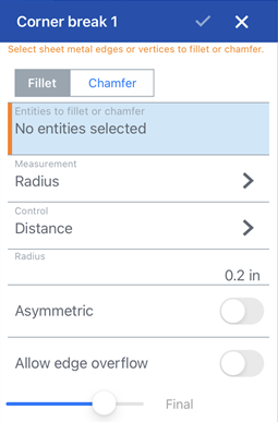
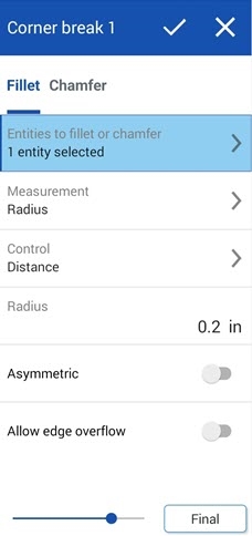
コーナー切断: iOS (上の最初の画像) と Android (上の2番目の画像) のフィレットダイアログ
- コーナー切断のタイプとして [フィレット] をタップします。
- グラフィック領域でシートメタルモデルのコーナー、エッジ、または頂点を選択します。
- 測定タイプを次のいずれかから選択します。
- 半径 - フィレットの半径方向の寸法を指定します。
- 幅 - フィレットの 2 つの端点間の距離 (一定の幅) を指定します。
- 制御タイプを選択します。
- 距離 - フィレットには半径の値が入力された円形エッジがあります。Onshape は、新しいフィレットを作成するときにこの値を記憶します。
- 円錐 - フィレットには、半径の値を入力した円錐のエッジと、必要に応じてフィレットのスタイルを定義する Rho 値があります。

Rho values: 0.25 (left; elliptical curve); 0.5 (middle; parabolic curve); 0.999 (right; hyperbolic curve - zoomed in)
- [曲率] - フィレットは、周囲のエッジの曲率を、入力した半径の値および必要に応じて 0 ~ .999 の間のマグニチュード値を一致させ、接線を調整します。
半径値を入力するときは、次の図に示す矢印で示されているドラッグマニピュレータを使用して、フィレットを視覚化し、推定値に近づけることもできます。
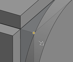
- [非対称] をオンにし、[2 つ目の半径] を入力すると、フィレットしたエッジの一方の端のフィレットエッジの半径の値が変わります。[非対称に反転] 矢印をクリックすると、フィレットのもう一方の端が 2 つ目の (非対称) フィレットエッジとして使用されます。
- 既定では、[エッジオーバーフローを許可] は、必要に応じて接線エッジをフィレットサーフェスから「削除」できるように設定されています。既定で生成されるエッジは、フィレットエッジに沿ってフィレットの方向を厳密に拘束します。[エッジオーバーフローを許可] を有効にすると、フィレットによって作成された面のエッジを修正して、滑らかで連続したサーフェスを作成できます。このオプションを無効にすると、フィレット面のエッジが保持され、より自由に流れるパーツになります。
[維持するエッジ] フィールドをタップし、グラフィック領域で維持するエッジを選択します。
- チェックマークをタップして、新しいコーナー切断のフィーチャーを確定します。
シートメタルモデルに面取り付きコーナー切断を作成するには、次の操作を実行します。
- 既存のシートメタルモデルがある Part Studio で [コーナー切断] (
 ) をタップします。
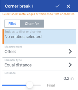
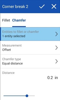
コーナー切断: iOS (上の最初の画像) と Android (上の2番目の画像) の面取りダイアログ
- コーナー切断のタイプとして [面取り] をタップします。
- グラフィック領域でシートメタルモデルのコーナー、エッジ、または頂点を選択します。
- 測定タイプを次のいずれかから選択します。
- オフセット - 距離フィールドに入力された開始エッジから面取りまでの距離を設定します。このオプションはエッジに依存し、計算は最初の選択から始まり、チェーン全体に進んでいきます。
- 接線 - 距離フィールドに入力された隣接する 2 つの面の接線の交点から面取りまでの距離を設定します。このオプションはエッジに依存しません。
- 面取りのタイプを選択します。
- 等距離 - 面取りはエッジから両方向に等しい距離まで延長します。
- 2 つの距離 - 面取りは各方向に異なる距離まで延長します。
- 距離と角度 - 面取りは、一方向に指定された距離まで延長され、もう一方向は指定した角度だけ延長されます。
- 面取りの距離を入力します。Onshape の既定の角度は 45 度ですが、[等距離] および [距離と角度の面取り] に最後に入力された距離の値は記憶されます。
- [2 つの距離] または [距離と角度] を選択した場合は、矢印ボタンをタップしてすべてのエッジの方向を反転するか、[方向のオーバーライド] フィールドで個々のエッジを指定して反転させます。
- チェックマークをタップして、新しいコーナー切断のフィーチャーを確定します。
-
コーナー切断のフィーチャー適用すると、すべてのモデルジョイントのタイプ (リッピングまたは曲げ) とスタイル (エッジジョイントまたは開先溶接) はシートメタルテーブルと展開図で編集できなくなります。シートメタルモデルのフランジとジョイント編集をすべて完了した後に、コーナー切断のフィーチャーを追加することをお勧めします。
-
コーナー切断を使用すると、コーナーだけでなく、曲げリリーフのエッジや頂点にもフィレットや面取りを適用できます。

-
コーナー切断のフィーチャーを 1 つ使用して、複数のフィレット、面取り、または両方の組み合わせをコーナーに追加することはできません。コーナー切断のフィーチャーを追加して、既存のコーナー切断のフィーチャーの任意の頂点またはエッジにフィレットまたは面取りを追加します。

2 つ目のコーナー切断のフィーチャーを使用して面取りしたエッジにフィレットを適用
シートメタルモデルがアクティブの場合 (作成または編集中) は、次のツールを使用できます。
-
 フランジ - 選択したエッジごとに壁を作成し、選択したエッジに曲げを用いて接続します。
 -
 タブ - シートメタルフランジにタブを追加します。
 -
 ジョイントを作成 - 2 つの壁の交差を、曲げ (円筒状のジオメトリで結合された壁) またはリップ (2 つの壁の間の小さなギャップ) のジョイントフィーチャーに変換します。
 -
 コーナー - コーナータイプとリリーフスケールを修正します。
 -
 曲げリリーフ - 曲げリリーフ (曲げの端がフリーエッジに接する部分に作られた小さなカット)、深度、およびリリーフ幅を修正します。
 -
 コーナー切断 - フィレットまたは面取りを適用して、既存のシートメタルパーツのコーナーを切断します。コーナーのエッジまたは頂点を選択し、コーナー切断のタイプと距離を指定します。このフィーチャーは、シートメタルモデルすべてのフランジとジョイントが完成してから使用することをお勧めします。
 -
 シートメタルモデル仕上げ - シートメタルモデルを閉じ (非アクティブにする)、フィーチャーリストにフィーチャーを作成します。