Render Studio Interface - Scene List
![]()
Only available for
Located on the left side of the page, the Scene list provides part, Part Studio and Assembly information for the current Render Studio scene.
When an option in the Scene list is selected, the Scene, Appearance, and Environment panels to the right display related submenus and their editable parameters. See the Scene, Appearance , and Environment panel sections for a comprehensive list of parameter options.
The Appearance panel only shows available parameters if a single Scene list item is selected. Press the spacebar to deselect all items and then select one item in the Scene list.
Any entities in the scene list except Transforms and Projectors can be multi-selected (selected together in a grouped selection). Transforms and Projectors are single selections only.
The Scene list is split into two scrollable sections:
-
Scene list geometry (upper section) - Contains all the geometry in the scene, as well as any Transforms, Projectors, and Volumes (Render Studio Advanced only).
-
Appearances (lower section) - Contains all the Appearances used by the geometry in the scene.
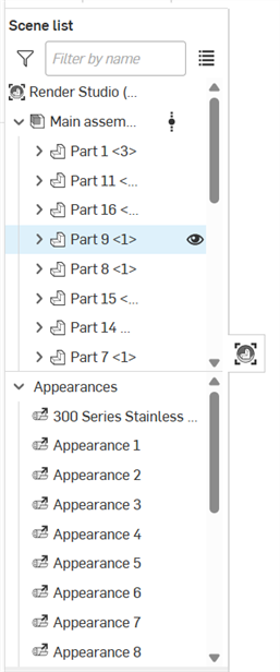
To adjust the Scene list width, hover the cursor over its right edge. When the cursor turns into a double-sided arrow, click and drag to resize.
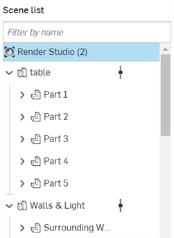
The Scene list has a hierarchical approach to the scene, and can be thought of in terms of levels. For example, in the image below, Render Studio is the top level, Table is one level below Render Studio, and Part 1 is a part one level below the table parts.
This concept of levels is important when it comes to setting precedence. A property on a level at the top takes priority over all levels below. If no property is set at the top level, but is set at the next level below, that property takes priority, and its property is applied to all lower levels. The exception to this rule is if a property at a higher level has an override set. If an override is set, then all levels below are overridden and will instead use this top level property.
For example, in the image below, if the table Part Studio has a property set, then all entities below (Part 1 to Part 5) use this property. If, on the other hand, the table does not have its property set, but Part 1 does, then the property set at Part 1 is used for all levels below. If an override exists in a level further up (for instance, on the table), then this property setting takes priority over anything set below its level (table and all parts below for example), even if any of them have their property set.
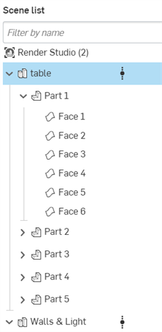
Entities in a Scene list cannot move from one layer to another (i.e.: up or down in the Scene list). The transform matrix, which determines where in space an item is located, is stored with the entity (as an entity instance). These transforms accumulate as they are added to each entity. Transform the top level entity, and all lower level entities transform accordingly; they are moved together as a group.
For example, select the top level Render Studio in the Scene list, and scale the y axis from 1 to 0.1 using the Transform tool. All parts in the scene are scaled down together (shown in the second image below):
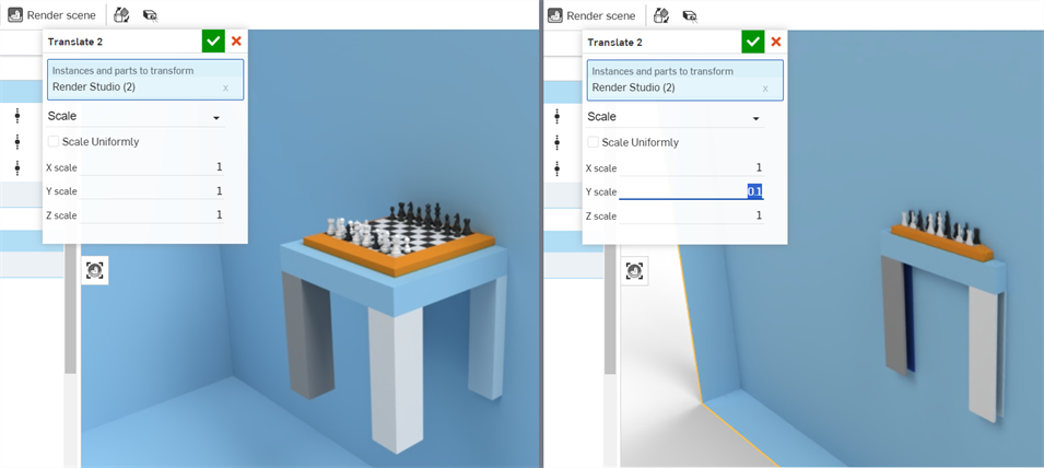
See Transform a Scene list entity for more information on part, Part Studio, and Assembly transforms.
Hover over the Scene list entity and the hovered entity's background turns light blue. A yellow outline surrounds the entity in the graphics area (see the first image below).
Click on the Scene list entity and the clicked entity's background turns a darker blue. A yellow fill is placed over the entity in the graphics area (see the second image below).
Both the outline and fill are visible even if the entity is behind another entity, as is the case in the images below, where the back face of the train's container is selected:
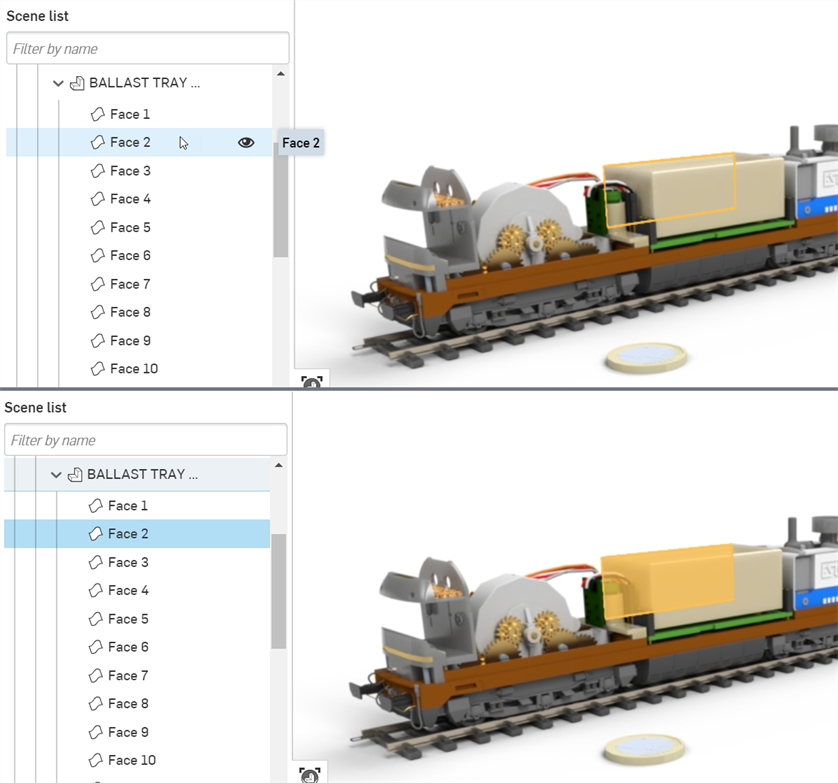
Alternatively, select entities directly in the graphics area.
Selections work like a toggle. Click to select, click again to deselect. You are also able to click to additively select and deselect (the same behavior you would expect from Ctrl+click).
See Selection for more information.
Use the Filter by name field to search the Scene list by the name of Scene list entities. Click the Filter toggle button (![]() ) to filter the Scene list contents by special filter commands (prefixed by a colon):
) to filter the Scene list contents by special filter commands (prefixed by a colon):
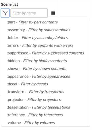
-
:part - Filter by parts, and optionally by name
-
:assembly - Filter by subassemblies, and optionally by name
-
:folder - Filter by assembly folders
-
:errors - Filter by contents with errors
-
:suppressed - Filter suppressed contents
-
:hidden - Filter hidden contents
-
:shown - Filter shown contents
-
:appearance - Filter by appearances.
-
:decal - Filter by decals
-
:transform - Filter by transforms (translate, rotate, scale)
-
:projector - Filter by projectors
-
:tessellation - Filter by tessellations
-
:reference - Filter by references
-
:volume - Filter by volumes
You can combine filters to get more detailed results, such as:
-
:assembly :errors to find all assemblies with errors, optionally include an assembly name
-
:part :hidden to find all parts that are hidden, optionally refined by including a part name
When a filter or name is entered into the filter field, the Filter icon (![]() ) turns blue to indicate a filter is being used. Use the Clear icon (
) turns blue to indicate a filter is being used. Use the Clear icon (![]() ) to the right in the Filter field to clear the filter:
) to the right in the Filter field to clear the filter:
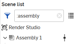
Selecting a filter command from the list removes/replaces any existing filters in the filter field.
Typing the filter (for example :errors) into the filter field produces the same result as selecting it from the list.
| Icon | Description |
|
|
Top level Render Studio scene |
|
|
Part Studio |
|
|
Configured Part Studio |
|
|
Assembly or subassembly |
|
|
Configured Assembly or subassembly |
|
|
Part |
|
|
Configured part |
|
|
Surface or face (mesh) |
|
|
Assembly folder |
|
|
Projector |


|
Indicates reference updates. See Updating references for a complete list of reference update icons and their meanings. |
|
|
Denotes a tessellation value other than Auto is applied. |
|
|
Show/hide a scene list entity. |
|
|
Transform (translate) |
|
|
Transform (rotate) |
|
|
Transform (scale) |
|
|
Appearance |
|
|
Linked appearance |
|
|
Decal |
|
|
Linked decal |
|
|
Volume (Render Studio Advanced only). See Creating a Volume. |
Components in the Scene list:
-
Filter button and field - Filter items within the Scene list. This is useful for scenes that contain many parts, Part Studios, or Assemblies. Faces cannot be filtered. For advanced filtering options see Filtering the Scene list.
-
Show search results as list (
 ) - Shows the search results as a flat list instead of a hierarchy:
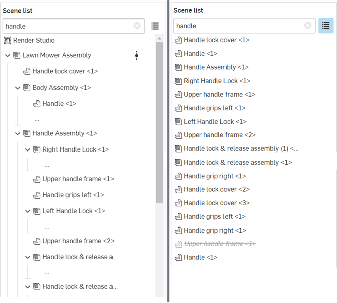
Scene list results with the default hierarchy view (left) and list view (right)
-
Render Studio - Root directory for the current scene. All other scene nodes are listed under the Render Studio: inserted parts, Part Studios, Assemblies, and Projectors.
-
Part Studio/Assembly parent groups - When a scene is created, parts, Part Studios, or Assemblies are inserted into the scene. These are the top level groupings for any parts or faces contained within these parts, Part Studios or Assemblies.
Entities found below the Part Studio or Assembly parent groups are:
-
Subassembly - An assembly within a parent Assembly. Subassemblies contain parts. surfaces, and faces.
-
Part - A single closed solid body with multiple faces. parts are the first level below the Part Studio/Assembly parent group or below subassemblies.
-
Surface - Entities that may have one or many faces but no volume, and are independent of parts. Surfaces are the first level below the Part Studio/Assembly parent group.
-
Face (mesh) - A portion of a part or surface region having area and bounded by edges. For example, a rectangular part has six faces. Faces do not necessarily need to be bounded by edges, such as a sphere. When the arrow to the left of the part name is clicked, the faces are expanded beneath.
-
Folder - When inserting an assembly into Render Studio, any folders and the folder structure are maintained. Like any other scene list component, folders can be shown, hidden, isolated, or suppressed.
Folders cannot be reordered or moved in Render Studio. You can, however, reorder them in the Assembly, create a new version, and update the reference in Render Studio. See Updating a Render Studio Scene entity for more information.
-
-
Transforms - Displays a list of all transforms (Translate, Rotate, Scale) performed in the Scene using the Transform tool on the Toolbar. See Transform a Scene list entity.
-
Appearances - Displays a list of all imported (linked) and applied part/face appearances in the scene. If one appearance is selected, its parameters are editable in the Appearance panel. If multiple Appearances are selected, they are displayed as a list in the Appearance panel. See Selecting multiple Appearances for more information.
-
Projectors - Displays a list of all Projectors in the scene. Projectors can have influence over any entity in the scene, and even the entire scene. Projection determines how the appearance texture mapping transforms, rotates, and scales when projected onto scene faces and/or parts.
-
Volumes (Render Studio Advanced only) - Displays a list of all Volumes in the scene. Volumes are cubic regions in which the volumetric portion of an appearance exists and is rendered. The volume can optionally be an OpenVDB 3D texture. Non-advanced users can open a scene that contains Volumes, but their properties are non-editable.
You can drag an Appearance from the Appearances list and drop it directly on an entity in the scene list (Render Studio, Part Studio, Assembly, Part, or face). This is a quick way to assign appearances directly from inside the Scene list. See Adding an Appearance to a Scene list entity.
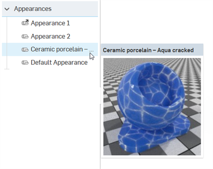
Hovering over an appearance displays its thumbnail to the right. This allows you to preview the appearance directly from the Appearances list:
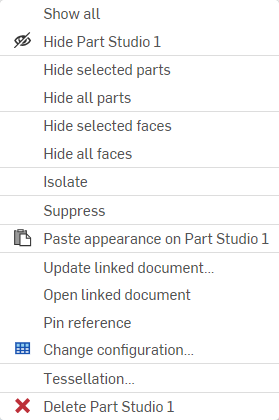
Right-clicking on a Scene list entity (Render Studio, Part Studio, Assembly, Assembly folder, part, or face) provides the following context menu options:
Not all options are available for all scene list entities. The options depend on what scene list entity is right-clicked.
-
Show all - Shows all items in the Scene list.
-
Hide (
 ) / Show (
 )
- Available from any Scene list item except Transforms, Appearances, and Projectors, this option toggles the visibility of a part or instance off or on in the scene. For example, when a part is selected, an eye icon is displayed to the right of its name. Clicking this icon hides the part's visibility in the scene. Clicking the icon again shows the part.
-
Hide all parts - Hides all parts from the current selection and below.
-
Hide all faces - Hides all faces from the current selection and below.
-
Isolate - Available only when one or more Parts, Part Studios, or Assemblies are selected from the Scene list's right-click context menu (not available for the Render Studio or face entities). When Isolate is selected, all selected entities are viewable and all other entities are hidden in the graphics area.
A banner is displayed at the top middle of the graphics area to indicate your are in isolate mode. Click Done to exit this mode.
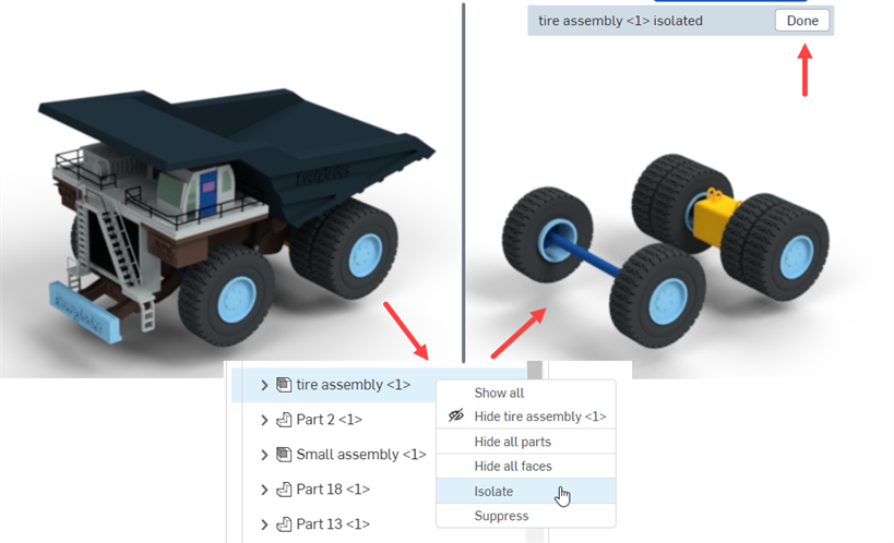
Isolate can also be applied to Transforms and Projectors from their respective context menus. See Transforms context menu and Projectors context menu for more information.
-
Suppress/Unsuppress - Hides one or more entities from the scene. When suppressed, the entity is not visible in the graphics area. Any entity except faces can be suppressed. Suppressing an entity that has children suppresses all children.
When an entity is suppressed, its name is italicized, font dimmed, and text contains a strikethrough. Right-click and select Unsuppress to toggle the entity back to an active state:
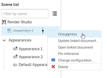
When suppressed, any associated scene list appearances, transforms, and projections are not removed from the Scene list. However, they are not visible in the graphics area.
-
Paste appearance - If you have copied an Appearance from the Appearances Library, Appearances list, or graphics area, use this option to paste it to the currently selected Scene list entity. See Copying and pasting Appearances.
-
Unassign appearance - Removes the appearance from the selected entities.
-
Link to Part Studio appearance - If a part is inserted in the scene that has Part Studio material/appearance assigned to it, and this appearance is unassigned, this option re-links the original Part Studio appearance to it.
Both parts and/or faces can be selected (individually or via multiple selection) and relinked to the original Part Studio appearance.
A part must be fully unassigned for the option to show up in the part's context menu. If a part has a mix of assigned and unassigned faces, the face(s) must be selected for the option to show up in the part's context menu.
There are two scenarios when using this option on faces. In this example, a Render Studio appearance is assigned to the part, and a different Render Studio appearance is assigned to the face.
-
If the part's face did not have a Part Studio appearance assigned to it, right-clicking on the face and selecting Link to Part Studio appearance causes it to be linked to the Part's Render Studio appearance, not the Part Studio appearance.
-
If the part's face had a Part Studio appearance assigned to it, right-clicking on the face and selecting Link to Part Studio appearance causes it to be linked to the Part Studio's (face) appearance.
See Part Studio Material to Render Studio Appearance mapping for more information.
-
-
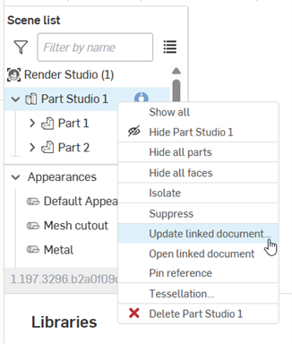
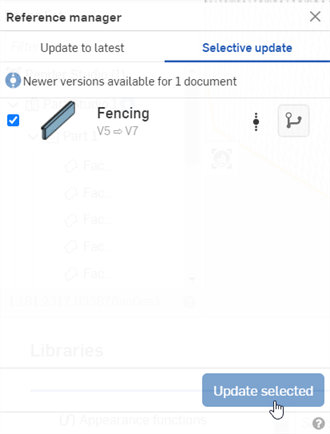
Update linked document - Opens the Reference manager dialog where you can update to the latest version or selectively update the document version. See Updating a linked Scene entity for more information.
-
Open linked document - Opens the linked document (Part Studio or Assembly) in a new browser tab.
-
Pin / Unpin reference - When pinned, the instance is linked to the latest version on its branch and is pinned.
-
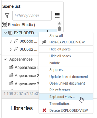
Exploded view - If an imported Assembly has one or more exploded views, use this option to open a dialog where you can select an Exploded view associated with the Assembly. The selected exploded view is now visible in the graphics area. See Accessing an Assembly's Exploded view.
-
Change configuration - Opens the Select configuration dialog, where you can choose a different Configuration for the Part Studio or the Assembly. See Inserting Part Studios or Assemblies with configurations.
-
Reset all tessellation - Available only from the top-level Render Studio entity's right-click context menu, this opens a message prompt to reset custom tessellation settings for all entities below to Auto. Click the Reset button to reset all tessellation, or Cancel to close the message prompt without making any changes:

-
Select matching instances - Available only from a part or subassembly beneath an inserted Assembly, this selects all matching instances of the part or subassembly. One use is for parts that are patterned, where this option selects all patterned part instances.
-
Tessellation - Opens the Tessellation dialog where you can select a different tessellation value for the currently selected Scene list entity (Render Studio, Part Studio, Assembly, or part). Options are: Auto, Coarse, Medium, Fine, Very fine, or Custom. If Custom is selected, additional options are available:

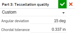
Tessellation settings apply to all entities below that do not have an explicit setting. For example, applying a Tessellation setting of Fine to an Assembly applies this same setting to all entities underneath the Assembly that do not have an explicit setting.
If a tessellation value other than Auto is applied, the tessellation icon is displayed next to the element in the Scene list:
-
Angular deviation - Controls how many segments curved surfaces are divided into during tessellation. For example, a value of 10 degrees will result in a cylinder with 36 planar faces.
-
Chordal tolerance - Maximum distance the tessellated geometry is permitted to vary from the underlying surface.
-
-
Delete - Deletes one or more selected top level parts, Part Studios, or Assemblies. You cannot delete faces or parts underneath a Part Studio/Assembly.
Hiding entities in the scene list does not persist after reloading the page or logging out. Any hidden entities are visible when the page is reloaded or after logging back in.
Transforms context menu
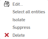
Right-click on a transform thumbnail in the Scene list Transforms to display a context menu with the following options:
-
Edit - Open the Transform dialog where you can make additional edits to the current transform.
-
Select all entities - Select all parts that were part of the transform operation.
-
Isolate - When selected, all entities with the selected transforms are viewable and all other entities are hidden in the graphics area.
A banner is displayed at the top middle of the graphics area to indicate your are in isolate mode. Click Done to exit this mode.
-
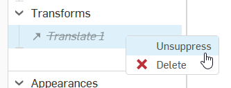
Suppress/Unsuppress - Suppress removes the effect the currently selected transform has on the scene.
When a transform is suppressed, its name is italicized, font dimmed, and text contains a strikethrough. Right-click and select Unsuppress to reapply the transform to the scene:
-
Delete - Restore the state of the part to its original placement prior to the transform and removes the current transform from the Scene list.
You can use the undo (![]() ) option on the toolbar to restore the transform, in the event you accidentally deleted it.
) option on the toolbar to restore the transform, in the event you accidentally deleted it.
Appearances context menu
Right-click on an appearance thumbnail in the Scene list Appearances to display a context menu with the following options:
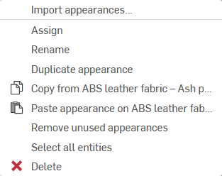
-
Use appearance from... - Allows you to select a Render Studio tab from the current or other document from which to bring applied appearances into the current Render Studio tab. See Using Appearances from another Render Studio tab for more information.
-
Assign - Assign the Appearance to the part(s) and clear any attribute lower down in the Scene list.
-
Rename - Rename the current appearance.
-
Unlink appearance - Unlink the Material that was originally assigned to the part in the Part Studio and then mapped to a Render Studio Appearance when the part is brought into a new scene. See Part Studio material to Render Studio Appearance mapping.
-
Duplicate appearance - Duplicates the current appearance and all its parameters. The copy is placed in the Appearances list directly under the currently-selected appearance.
-
Copy from [Appearance] (
 ) - Copies the currently selected Appearance in the Scene list to the clipboard.
 -
Paste Appearance on [Appearance] (
 ) - Pastes the Appearance from the clipboard (source Appearance) to the currently selected Appearance (target Appearance) in the Scene list. The source Appearance replaces the target Appearance.
 If the target Appearance was not previously renamed, the source Appearance name is used. If the target appearance was previously renamed, this name is retained when the source Appearance replaces the target Appearance.
-
Remove unused Appearances - If there are any Appearances in the list that are not being used in the scene, this option removes all of them from the Appearances list. This is helpful to de-clutter a lengthy list with many unused Appearances. If no Appearances are unused, a blue information message alerts you that nothing was removed.
-
Select all entities - Selects all parts/faces where this Appearance is applied in the scene.
-
Delete - Deletes one or more selected appearances from the Appearances list if they are unused. Used appearances cannot be deleted.
Linked appearances cannot be renamed.
Projectors context menu
Right-click on a Projector thumbnail in the Scene list Projectors to display a context menu with the following options:
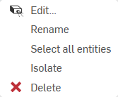
-
Edit - Open the Projector dialog where you can make additional edits to the current projector.
-
Rename - Rename the current projector.
-
Select all entities - Selects all entities and parts where this projector is applied in the scene.
-
Isolate - When selected, all entities with the selected projectors are viewable and all other entities are hidden in the graphics area.
A banner is displayed at the top middle of the graphics area to indicate your are in isolate mode. Click Done to exit this mode.
-
Delete - Deletes the projector and removes its influence on the associated entities and parts in the scene.
You can use the undo (![]() ) option on the toolbar to restore the projector, in the event you accidentally deleted it.
) option on the toolbar to restore the projector, in the event you accidentally deleted it.
Volume context menu (Render Studio Advanced only)
Right-click on a Volume thumbnail in the Scene list to display a context menu with the following options:
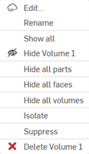
-
Edit - Open the Volume dialog where you can make additional edits to the current volume.
-
Rename - Rename the current volume.
-
Show all - Shows all items in the Scene list.
-
Hide (
 ) / Show (
 )
- Toggles the visibility of a volume off or on in the scene.
 -
Hide all parts - Hides all parts from the current selection and below.
-
Hide all faces - Hides all faces from the current selection and below.
-
Hide all volumes - Hides all volumes from the current selection and below.
-
Isolate - When selected, the current volume is viewable and all other entities are hidden in the graphics area.
A banner is displayed at the top middle of the graphics area to indicate your are in isolate mode. Click Done to exit this mode.
-
Suppress/Unsuppress - Suppress removes the effect the currently selected volume has on the scene.
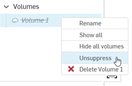
When a volume is suppressed, its name is italicized, font dimmed, and text contains a strikethrough. Right-click and select Unsuppress to reapply the volume to the scene:
-
Delete - Deletes the volume and removes its influence on the associated entities and parts in the scene.
-
To insert a part, Part Studio, or Assembly into a Render Studio scene:
-
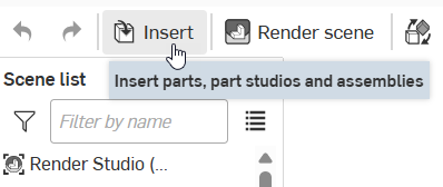
Click the Insert button (
 ) on the Toolbar:
-
The Select part, Part Studio, or Assembly dialog opens:
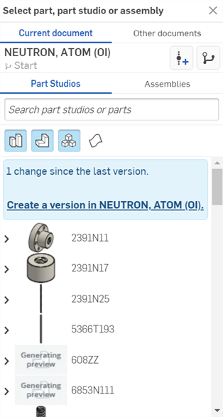
Render Studio scenes can be thought of as a snapshot (version) of the Document at the time an entity is first imported into the scene. For this reason, a version is required before an entity is imported. Click the "Create a version in [Document]" link, fill out the information in the Create version dialog, and click the Create button. Once this is done, all Document assets become available, and you can import any parts, Part Studios, or Assemblies from the Select dialog.
Once an entity is imported into the Render Studio tab, anything created in (or imported into) the document outside this Render Studio tab is not accessible to this Render Studio scene unless a new version is created.You can also click the Create version button (
 ) on the Document panel to open the Create version dialog and create a document version at any time. See Versions and history for more information.
 -
Select the entity you want to insert into the Scene by clicking on it. This can be a part, composite part, surface, Part Studio, or Assembly from the Current document or Other documents.
Only one entity can be inserted into the scene each time you access the Select part, Part Studio, or Assembly dialog; however, you can insert as many entities as you like into the same scene.
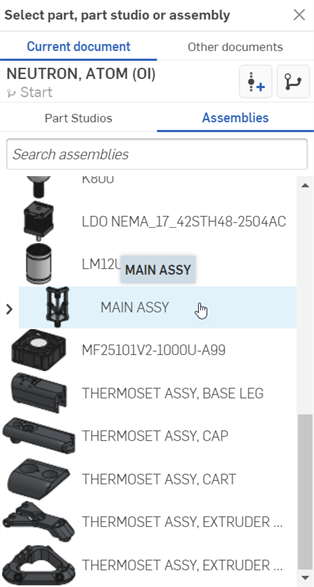
See Insert Parts and Assemblies for more information about the Insert (Select part, Part Studio, or Assembly) dialog.
A cosmetic thread is a visual representation of a thread that does not affect geometry. Onshape displays cosmetic threads for External threads and tapped Holes in a Part Studio. This allows for faster iteration and regeneration, since the thread geometry does not need to be recalculated. See Hole and External threads for more information.
When holes with cosmetic threads or parts with external threads are inserted into a scene, they are displayed in the same way as in a Part Studio.
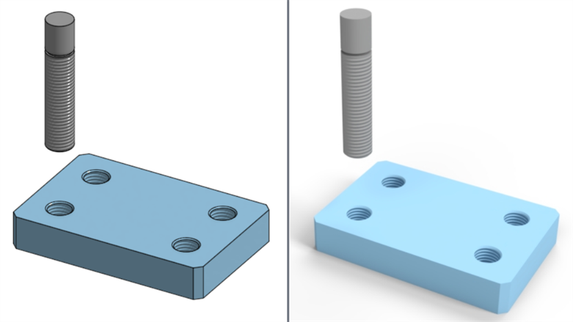
Cosmetic threads displayed in a Part Studio (left) and in a Render Studio (right)
After applying some appearances to the parts, they can be rendered with these cosmetic threads in place:
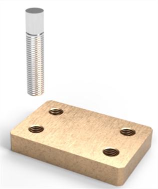
Cosmetic threads cannot be removed in the Render Studio scene. They can only be adjusted in the Part Studio.
If an entity used in a Render Studio scene is updated outside the Render Studio tab, the entity displays an update linked icon (![]() ) next to the scene entity. This indicates the referenced entity requires an update.
) next to the scene entity. This indicates the referenced entity requires an update.
If the updated entity is in the current workspace, a new version/update is not required, and the new entity is immediately available. A new version/update is only required for entities updated outside the current workspace.
To update a scene entity:
-
If there is a newer version of the document, the update reference icon displays next to the entity in the Scene list:

-
Right-click on the entity and select Update linked document from the context menu:
-
The Reference manager dialog opens. Check the entities to update, and then click the Update selected button:
-
The Render Studio tab reloads in the browser with the updated version applied.
-
Click the x in the upper right corner to close the dialog.
If your Assembly has one or more an exploded views, once inserted into the Scene, you can access any of these Exploded views to view them in the graphics area.
-
Right click on the Assembly in the Scene list and select Exploded view:
-
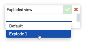
The Exploded view dialog opens:

-
Click the Default dropdown to select the desired Exploded view. Note that this list can contain several Exploded views:
-
Click the checkmark (
 ) to accept the new view.
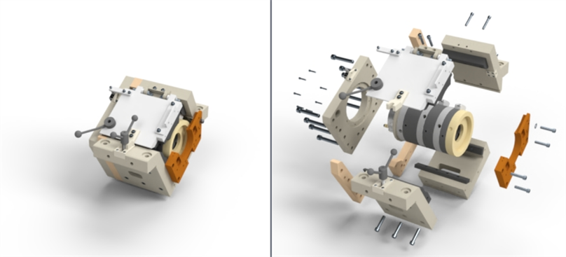
Default (non-exploded) view (left), and Exploded view (right)
You can switch between other Exploded views or back to the default (non-exploded view) at any time by accessing the dialog again and selecting Default from the dropdown and clicking the checkmark (![]() ) again.
) again.
-
Click the Insert button (
 ) on the Toolbar:
-
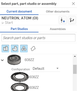
The Select part, Part Studio, or Assembly dialog opens:

-
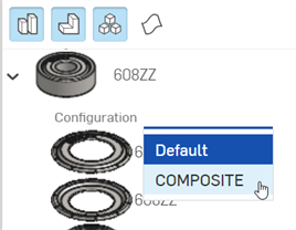
Locate the Part Studio or Assembly with additional configurations (shown in the first image below). Click the dropdown and select the desired configuration (shown in the second image below):
-
Click the configured Part Studio or Assembly to insert it into the Scene.
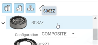
-
To select a different configuration for the Part Studio or Assembly after it is inserted into the scene, right-click on the Part Studio or Assembly in the Scene list and select Change configuration from the context menu:
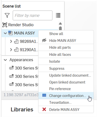
-
The Select configuration dialog opens:
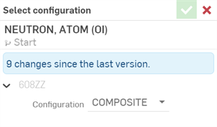
-
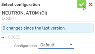
Click the dropdown to select a new configuration, then press the checkmark (
 ) to accept the new configuration and update the Part Studio or Assembly in the scene:
To transform one or more Scene list entities:
-
Click the Transform button (
 ) on the toolbar.
 -
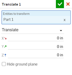
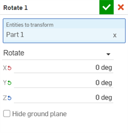
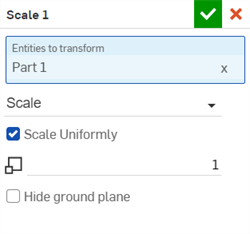
This opens the following dialog, where you can alter the Translation, Rotation, and Scale of the entities:
-
Entities to transform - Select all entities you would like transformed. This includes the top level Render Studio, Part Studios, Assemblies, parts, and volumes (Render Studio Advanced only). Faces cannot be transformed.
The origin point used for any transformations is the center of all entities to transform. For instance, if one part is selected, the center of that part is used as the origin point. If 2 parts are used, then the center of both parts combined is used as the origin point.
A bounding box is visible to show the origin and all entities included in the transform selection.
-
Transform dropdown - Select Translate, Rotate, or Scale. Only one transform operation can be performed per Transform dialog, but you can have multiple transforms in the same scene. All transforms are located in the Scene list. Transform options are:
-
Translate - Moves the selection along the x, y, and z axis, according to the origin point of the scene. Measurement units are in meters, and are negative or positive numbers.
-
Rotate - Rotates the selection along the x, y, and z axis, according to the origin point of the scene. Measurement units are in degrees, and range from -360 to +360 degrees.
-
Scale - Scales the selection up (larger) or down (smaller), along the x, y, and z axis, according to the center point of the selection. Measurements are based on the selection's original size. For example, a Scale of 1.000 x by 1.000 y means that the scale is 100% of the part's original size. Fractional numbers from 0.001 to 1 reduce the size of what is selected. Scale axes cannot be set to 0.
-
Scale uniformly - If the Scale transform is selected, keep this checkbox enabled to scale the entities and parts uniformly by the entered value. Uncheck to scale separately along the X, Y, and Z axes.
-
-
-
Hide ground plane - Hides the Environment's virtual ground plane. See Environment panel for more information on Ground settings.
Alternatively, you can pre-select the entities from the Scene list or graphics area before entering the Transform dialog. When you click the Transform button (
 ) on the toolbar, the Entities to transform field automatically populates with the selected entities.
 -
-
When using the Transform tool, adjust the manipulators in the graphics area if Translate or Rotate is selected in the dialog:

Translational manipulators (left); rotational manipulators (right).
Scale transforms are entered numerically in the dialog and do not have an associated manipulator in the graphics area.
-
When finished click the checkmark (
 ) to accept the new transform.
Multiple transforms are applied in the order they were created and listed in the scene list.
If entities in an Assembly are transformed, and then that Assembly is updated in the Render Studio, the Render Studio transforms are re-applied on top of the new Assembly transforms. In this way, Render Studio transforms are non-destructive.
For each transform, you can edit, select all transform entities, isolate, suppress, and delete it. See the Transforms context menu for more information.
Any Scene list entity or group of entities (the entire Render Studio, Part Studios, Assemblies, parts, and faces) can have their own associated Projector. The projector affects the Appearance/texture applied to the entity, but not the entity itself.
To associate a Projector to an entity:
-
Click the Projector icon (
 ) on the Toolbar:

-
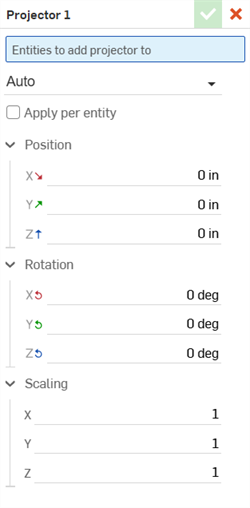
The Projector dialog opens. Enter the following information into the dialog:
-
Name [Projector 1] - Provide a name for the projector
-
Entities to add projector to - All entities affected by this projector. While the dialog is open, select any Scene list entities from the Scene list or graphics area. This includes the entire Render Studio, Part Studios, Assemblies, parts, and faces. They are added to the projector's influence.
-
Projection type - Select a projection type: Auto, Planar, Cubic, Cylindrical, Spherical, or Surface.
-
Normalized (Available only for Cylindrical or Spherical Projection types) - Check to have 1 rotation around the horizontal axis of projection cover 2 repeats of the texture, regardless of the size of the cylinder or sphere.
-
Capped (Available only for the Cylindrical Projection type) - Check to add a planar projection to the top and bottom of the cylindrical projection.
-
Apply per entity - Check to take into account the transform of the selected entities so that it moves with the entities.
-
Position (X/Y/Z) - Enter the positional transformations in length measurements along the X, Y, and Z axes.
-
Rotation (X/Y/Z) - Enter the rotational transformations in degrees along the X, Y, and Z axes.
-
Scaling (X/Y/Z) - Enter the scalar transformations in ratio values, with 1 being the original scale, along the X, Y, and Z axes.
Alternatively, you can pre-select the entities from the Scene list or graphics area before entering the Projector dialog. When you click the Projector button (
 ) on the toolbar, the Entities to add projector to field automatically populates with the selected entities.
 -
-
Use the projector transform tool to adjust the projector's Position, Rotation, and Scaling. Alternatively, transform the projector numerically in the dialog:
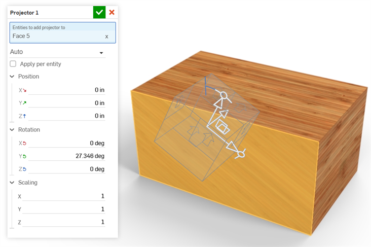
Transforming the projector applied to Face 5 on the model.
-
The projector's transform tool changes, depending on the selected Projection type:
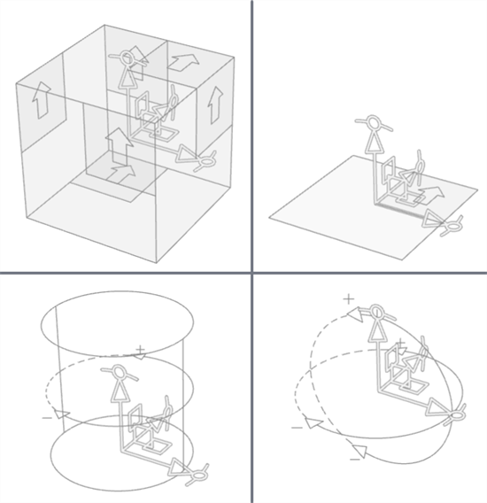
Clockwise from top left: Auto/Cubic, Planar, Spherical, and Cylindrical transform tools
-
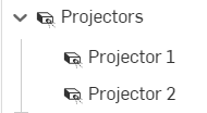
The projector is associated to the selected entities and parts and is located at the bottom of the Scene list under the Projectors dropdown:
Use appearances that are applied to entities from the current or other document's Render Studio tab in the current Render Studio tab:
From the Render Studio tab you want the appearances brought into:
-
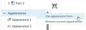
Right-click on the Appearances list or an appearance in the Appearances list and select Use appearance from... from the context menu:
-
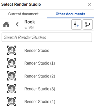
The Select Render Studio dialog opens. Select a Render Studio tab from either the Current document or Other documents:
-
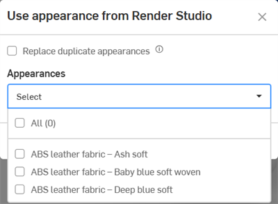
The Use appearance from dialog opens. Select from the following options:
-
Replace duplicate appearances - When checked, if the current Render Studio tab has appearances with the exact same name as those in the selected Render Studio tab, the appearance in the current Render Studio tab is overwritten with the appearance from the selected Render Studio tab. All parts/instances that had the previous appearance assigned are now assigned the appearance from the selected Render Studio tab.
If this option is unchecked, appearances with the same name brought in from the selected Render Studio tab have a sequential number added as a suffix to their name to make them unique.
- Appearances (Select dropdown) - Check All if you would like to bring all Appearances into the current Render Studio. Alternatively, check individual Appearances to bring them into the current Render Studio.
-
-
After making your selections in this dialog, click Apply to bring the appearances into the current Render Studio appearances list. Alternately, click Cancel to exit the dialog without any changes.
The appearances are brought into the current Render Studio tab's Appearances list in alphabetical order.
Tips
-
Unlike appearances in favorite folders, custom appearance parameter settings from the selected Render Studio tab are preserved.
-
If any appearance uses resources the user does not have permission to access, the appearance checkbox appears gray and cannot be selected.
-
You can create an empty Render Studio tab to act as an appearance container that houses all your frequently-used appearances from current and/or other documents' Render Studio tabs.
-
In the Use appearance from dialog, if All is checked and then unchecked, all appearances remain selected.
Decals created in a Part Studio are imported into a Render Studio when that Part, Part Studio or Assembly that uses them is inserted into the Render Studio. See Decal for information on how to create a decal feature in a Part Studio.
Once the Part, Part Studio or Assembly is inserted into the Render Studio, the decal is converted to an appearance located in the Scene list's Appearances list:
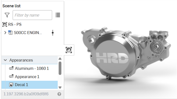
The Decal is linked to the Part Studio feature, as indicated by an arrow on the Decal icon (![]() ). Any edits to the Decal in the Part Studio updates to the Render Studio after a document version is created and the reference is updated in the Render Studio.
). Any edits to the Decal in the Part Studio updates to the Render Studio after a document version is created and the reference is updated in the Render Studio.
If any of the decal's parameters are edited in the Appearance panel, the link icon displays an unlinked decal (![]() ). However, unlike other Appearances, the decal appearance continues to track the decal projection and UV placement if modified in the source Part Studio.
). However, unlike other Appearances, the decal appearance continues to track the decal projection and UV placement if modified in the source Part Studio.
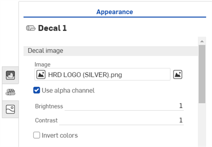
The Decal's editable parameters in the Appearance panel are outlined below:
-
Decal image
-
Image - The decal image file. Click the image field to open the Select image dialog, where an image can be selected from the current document, other documents, or imported from your computer to replace the current image.
-
Use alpha channel - When checked, if the image has a transparent alpha channel, it is used to trim the decal.
-
Brightness - Specifies the image brightness on a scale from 0-1.
-
Contrast - Specifies the image contrast on a scale from 0-1.
-
Invert colors - Reverses the colors of the image.
-
-
Decal appearance
-
Diffuse roughness - Roughness value of the decal appearance. Higher roughness values lead to a more powdery look.
-
Metallic appearance - The metallic value of the decal. With a value of 1.0, reflection is colored and independent of view direction. With a value of 0.0, reflection is white and direction-dependent. Directional dependence is in this case based on the IOR (Fresnel effect).
-
Reflection roughness - Reflection roughness value of the decal appearance. Higher roughness valued lead to more blurry reflections.
-
Reflection weight - Controls the amount of reflection.
-
Reflection anisotropy - Reflection anisotropy value of the decal appearance. Higher values stretch the highlight.
-
Anisotropy rotation - Changes the orientation of the anisotropy. A value of 1 rotates the orientation 360 degrees.
-
IOR - Determines refraction in the volume. It also influences the reflectivity for decals that are not metallic.
-
Bumps - Attach a bump or normal map to the decal via one of the Bump functions in the Appearances library.
-
-
Decal transmission
-
Transmission color - Color effect for transmission independent of thickness of the decal, similar to stained glass.
-
Transmission weight - Weighs how much light passes through the decal, compared to its diffuse reflectivity.
-
Transmission roughness - The roughness value of the transmission. Higher values lead to decals seen through the Appearance to appear blurry.
-
Tips
-
Unlike other Appearances, decals cannot be selected from the Appearances library. Therefore, they cannot be assigned to any entity within a Render Studio. They can only be inserted as an external reference from a source Part Studio.
-
Decals cannot be duplicated or removed.
-
Decals cannot be hidden. To work around this issue, you can set the decal's Transmission weight to 1. The decal becomes transparent; However, this is only valid if the Transmission color is set to white, and the decal is matte (without any appearance parameter making it shiny). Otherwise, the face may not look accurate.
-
You cannot have more than 3 overlapping decals applied on a planar face, or more than 3 decals applied to a cylindrical face. Additional decals are still imported into Render Studio, but will not be visible on the face.
-
The order in which decals were created in the source Part Studio determines the order in which they are applied in the Render Studio at the time of import.
See Render Studio Examples and Resources for more information.