Render Studio Interface - Appearances Library
![]()
Only available for
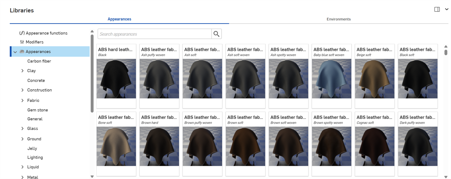
Located at the bottom of the page, the Appearances library contains all the standard attribute combinations that are applied to parts, part faces, or surfaces, to provide a material texture, as well as functions that are applied to appearance parameters:
Search
Use the Search appearances field to narrow the appearance results in the library. The Search appearances field only locates appearances within the selected folder. For example, in the image above, if the Ceramic folder is selected, typing a keyword into the Search appearances field and pressing the Enter key shows only results within the Ceramic folder.
Use "and", "+", and "or" operators between words to further refine the search.
Once narrowed by the search, results appear as a thumbnail list on the right side of the Appearances panel. To clear the search, delete the keyword(s) in the Search appearances field and press the Enter key or press the clear field icon (![]() ).
).
Switching between the horizontal and vertical library views
Click the Show library in the right panel icon at the top right corner of the panel to show the library in the right panel:

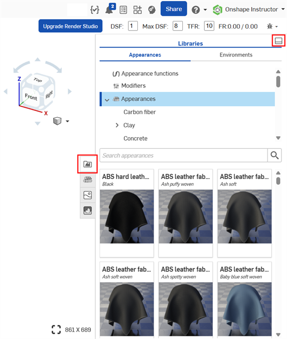
Click on the library panel icon (![]() ) to close the panel. Click it again to open it.
) to close the panel. Click it again to open it.
To place the library back in its default horizontal position, click the Show library in the bottom panel button located at the top right corner of the panel (highlighted in red in the above image).
To apply an Appearance function to an Appearance parameter while the Appearances library is in the right panel, drag the Appearance function on top of the Appearance panel icon and hold until it opens. Then drop the Appearance function on the parameter in the panel. See Using appearance functions for more information.
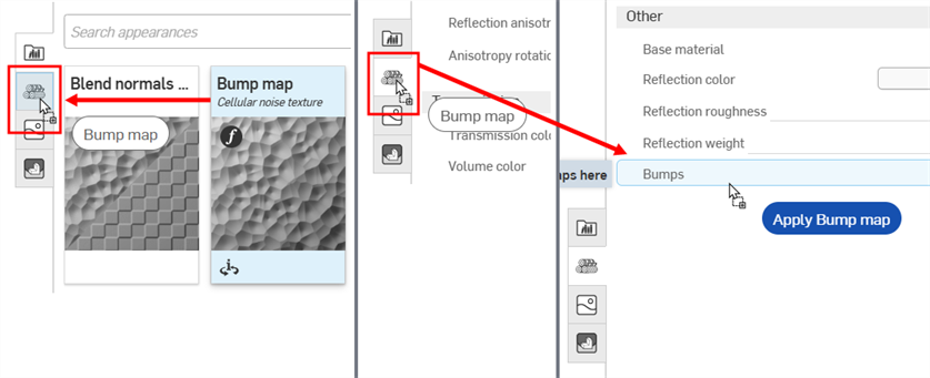
Dragging the Bump map Appearance function over the Appearance panel icon (left). The Appearance panel opens (middle). While still holding, drag the Bump map Appearance function on top of the Bumps parameter in the Appearance panel (right).
Hide/Show library
To hide/show the Libraries panel, click the expand/collapse toggle (![]() ) at the top right corner of the panel.
) at the top right corner of the panel.
View Appearance name
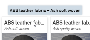
If the entire name of the Appearance is not visible, hover over the name and a tooltip reveals the complete name:
View Appearance description
Click the View description toggle (![]() ) at the bottom of the Appearance card (top left image below) to flip it and reveal a short description of the Appearance on the back of the card (top right image below). If the description is too long for the card container, hover your cursor over the text for a moment and the card expands to reveal the full description (bottom image below). Click the View description toggle again to flip the card to the thumbnail on the card front.
) at the bottom of the Appearance card (top left image below) to flip it and reveal a short description of the Appearance on the back of the card (top right image below). If the description is too long for the card container, hover your cursor over the text for a moment and the card expands to reveal the full description (bottom image below). Click the View description toggle again to flip the card to the thumbnail on the card front.
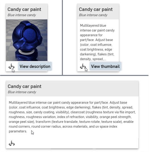
Only one Appearance card can be flipped to the back description at a time. Clicking a second Appearance's View description toggle simultaneously flips the first Appearance's description view to the front (thumbnail) and flips the second Appearance's view to the back (description).
See Render Studio Libraries for a complete list of all appearances and appearance functions.
See Appearance panel for an explanation of the default Appearance parameters.
Tips
-
If an appearance cannot be assigned to a part (the context menu options are not available or do not display when using drag and drop to apply an appearance to a part), it probably means the appearance is a function. Functions must be applied to appearance parameters in the Appearance panel (via drag and drop). See Using Appearance functions for more information.
-
Once an Appearance is applied to a part, Part Studio, or Assembly, check the Appearance panel and browse through the appearance's submenus. This panel contains all editable parameter options for the current Appearance.
-
If the Appearance panel is empty, most likely there are multiple items selected in the Scene list or graphics area. Deselect all but one item, and the Appearance panel should populate with applicable parameters.
-
If the appearance is a light source (Add emission, Diffuse light, Photometric light, Spot light), ensure some walls or other parts are modeled so the light has something tangible against which to reflect. If the light is black, increase the Intensity and/or Unit scale parameter in the Appearance panel. See Light emission for more information.
-
If the appearance contains a pattern or texture that does not appear on the part, it might be too small or too large. In the Appearance panel, increase or decrease the Scale parameter. In addition, try increasing the Intensity parameter, if it exists.
-
To adjust the Appearances/Environments Libraries panel height, hover the cursor over a panel edge. When the cursor turns into a double-sided arrow, click and drag to resize the panel.
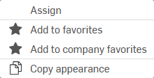
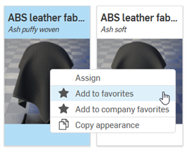
Right-click on an appearance thumbnail in the Appearance library to display a context menu with the following options:
-
Assign - Assign the Appearance to the part(s) and clear any attribute lower down in the Scene list.
-
Add to favorites - Add the selected Appearance to the My favorites folder. See Working with favorites for more information.
-
Add to company favorites - Available only in a company (for Pro plans) or enterprise (for Enterprise plans) and the user has the required permissions to edit the company favorites. Add the selected Appearance to the Company favorites folder. See Working with favorites for more information.
-
Copy Appearance (
 )
- Copy the current Appearance to the clipboard.
When an Appearance is assigned to an entity, all entities below in the Scene list that do not have an explicit Appearance assigned to them will have this Appearance assigned to them as well. For example, applying a metal Appearance to an Assembly in the Scene list applies this same metal Appearance to all entities underneath the Assembly that do not have an explicit Appearance assigned.
When assigning an Appearance to a part that has Appearances already assigned to faces below it, the following dialog is displayed:

Clicking the Clear face appearances link removes all of the part's underlying face appearances' assignments and applies the newly assigned Appearance to the entire part.
This procedure counts as 2 distinct undo steps:
-
Clearance (removal) of Appearances from all the part's faces
-
Assignment of the new Appearance to the part (and all the part's faces).
If you instead press the x to dismiss the message, any of the part's faces that have assigned Appearances retain those Appearances, and the Part Appearance is applied only to the Part and all the part's faces without assigned Appearances.
In the example below, a brushed metal Appearance is assigned to the outer crown face of the Rook model. A blue ceramic Appearance is then assigned to the entire Rook part. Pressing x to dismiss the Clear face appearances message results in the blue ceramic Appearance applied to all part faces except the outer crown face that preserved the brushed metal Appearance (shown below left). Alternatively, pressing the Clear face Appearances link results in the brushed metal Appearance cleared (removed) from the outer crown face, and the part (and all underlying part faces) having the blue ceramic Appearance applied (shown below right):
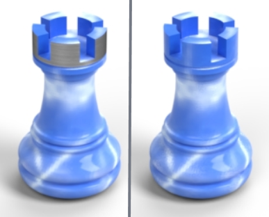
Without face appearances cleared (left), and with face Appearances cleared (right)
There are 6 ways to assign an Appearance to a Scene entity (Render Studio, Part Studio, Assembly, part, or face). Do one of the following:
To apply an Appearance to multiple Scene list entities, pre-select the entities in the Scene list or graphics area. Assigning or dragging and dropping the Appearance on one of the selected entities assigns the Appearance to all entities.
If dragging an Appearance, it can only be dropped on a part, not a face. To assign an Appearance to one or more faces. select the face(s) first, then right-click on the Appearance in the Appearances library and select Assign from the context menu. Alternatively, drag and drop the Appearance on one or more faces in the Scene list.
Some appearances are functions, and some of those functions cannot be added using the methods outlined below. See Using Appearance functions for more information.
-
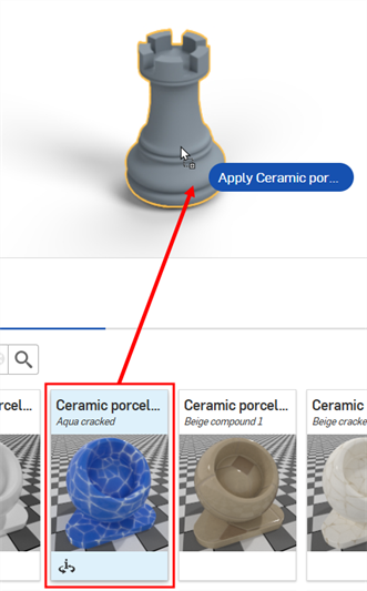
Drag and drop the Appearance from the Appearances library to the selected part in the graphics area. You can only apply appearances to parts using this method, not faces.
-
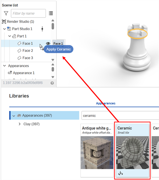
Drag and drop the Appearance from the Appearances library to the selected entity in the Scene list. Using this method, you can apply the Appearance to the Render Studio, Part Studio, Assembly, part, or face:
-
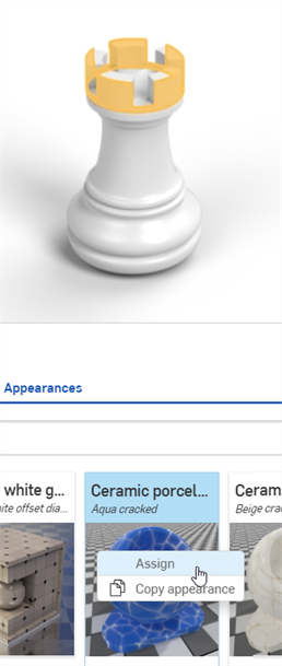
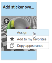
Select the entity in the Scene list or graphics area, then right-click on the Appearance in the Appearances library and select Assign from the context menu:
-
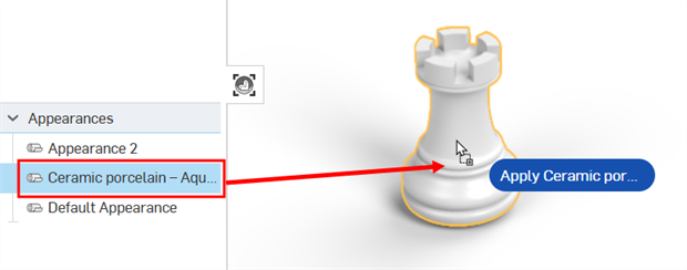
If the Appearance you want to assign already exists in the Scene list (under the Appearances list), drag and drop it directly on a part in the graphics area. You can only apply appearances to parts using this method, not faces.
-
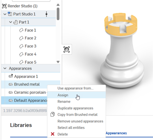
If the Appearance you want to assign already exists in the Scene list (under the Appearances list), select the entity in the Scene list or graphics area, then right-click on the Appearance and click Assign from the context menu:
-
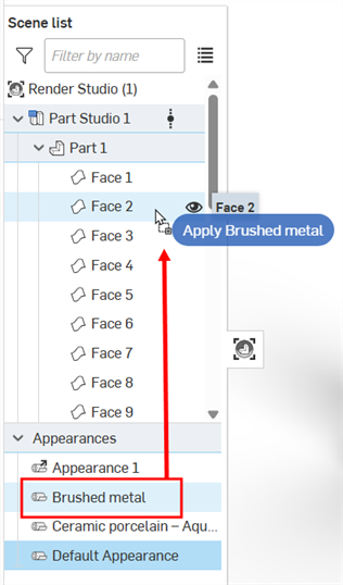
If the Appearance you want to assign already exists in the Scene list (under the Appearances list), select the entity in the Scene list or graphics area, then drag and drop the Appearance from the Appearances list directly to one of the selected entities in the scene list:
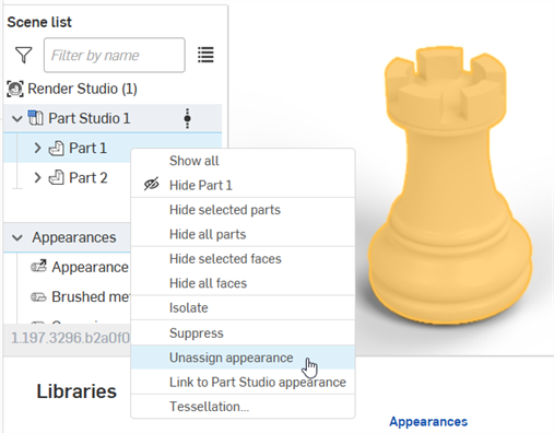
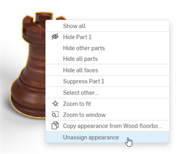
To remove an appearance from a part or face, do one of the following:
-
Select one or more parts or faces in the Scene list, then right-click and select Unassign appearance from the Scene list context menu:
-
Right-click on the part or part face in the graphics area and select Unassign appearance from the context menu. Only one part or face appearance can be removed at a time using this method:
Appearances can be copied from the following locations. In all cases right-click and select Copy Appearance from the context menu:
-
An Appearance in the Appearances library
-
An Appearance in the Appearances list (under the Scene list).
-
The part or face in the Graphics area
Once the Appearance is in the clipboard it can be pasted into:
-
One or more parts or faces in the graphics area. Right click over any highlighted entity (part or face) and select Paste Appearance on entity. If multiple entities are selected, you can paste the appearance to multiple entities using the same context menu option.
-
An entity in the Scene list. The appearance can only be pasted to one entity. Pasting to multiple entities in the Scene list is not supported. However, you can paste to the top level Render Studio, which assigns the Appearance to all entities in the scene.
-
An Appearance in the Appearances list (under the Scene list). Right click over an Appearance and select Paste Appearance on [Appearance]
Alternatively, instead of using the context menu to copy/paste, you can drag and drop an Appearance in the following ways:
-
From the Appearances library to one or more parts in the graphics area. You can only apply appearances to parts using this method, not faces.
-
From the Appearance library to an entity on the Scene list (Render Studio, Part Studio, Assembly, Part, or Face).
-
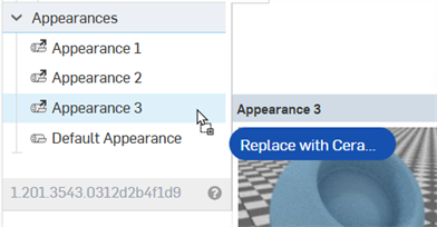
From the Appearance library to an Appearance on the Appearances list. When doing this, the Appearance in the Appearances list is replaced by the Appearance being dragged over it. Any element in the Scene list that was using the replaced Appearance now uses the new Appearance.
-
From the Appearance in the Appearances list to an entity on the Scene list (Render Studio, Part Studio, Assembly, Part, or Face).
-
From one Appearance in the Appearances list to another Appearance in the Appearances list. When doing this, the Appearance in the Appearances list is replaced by the Appearance being dragged over it. Any element in the Scene list that was using the replaced Appearance now uses the new Appearance.
-
From the Appearances list to one or more parts in the graphics area. You can only apply appearances to parts using this method, not faces.
You can also use ctrl/cmd+c to copy and ctrl/cmd+v to paste Appearances, provided your cursor is in the right location to allow it. For example, copy when hovering over an Appearance in the Appearances library and paste when hovering over a selected face or part in the graphics area.
Things to keep in mind:
-
Copying and pasting Appearances follows the same logic used when adding an Appearance. See Adding an Appearance to a Scene list entity.
-
If the target Appearance was not previously renamed, the source Appearance name is used. If the target Appearance was previously renamed, this name is retained when the source Appearance replaces the target Appearance.
-
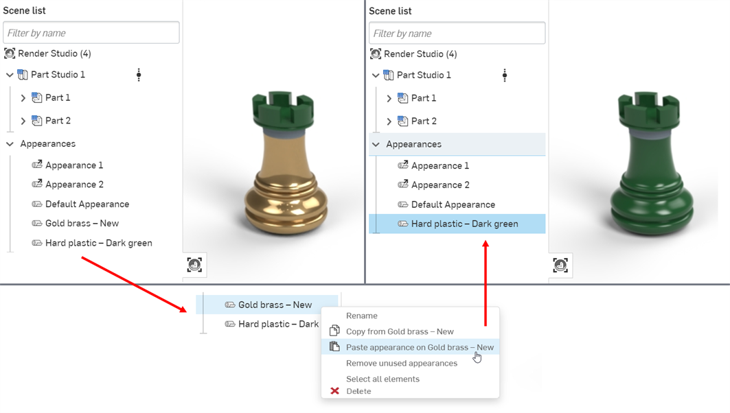
Copying an Appearance from the Appearances list (source) and pasting it to another Appearance on the Appearances list (target) replaces the target Appearance and removes it from the Appearances list. All entities that were previously assigned the target Appearance are now assigned the source Appearance.
For example, in the image below the Hard plastic — Dark green Appearance is copied and pasted into the Gold brass — New Appearance. This removes the Gold brass — New Appearance from the Appearances list, and any previous entities which were assigned the Gold brass — New Appearance are now assigned the Hard plastic — Dark green Appearance.
-
If pasting to a linked Appearance, the link is broken and the new Appearance replaces the linked Appearance.
Any user can add any Appearance to the My favorites folder. If you are in a company (for Pro plans) or enterprise (for Enterprise plans) and have the required permissions to edit the company favorites, you can add any Appearance to the Company favorites folder. Both these folders help you catalog and have quick access to frequently-used Appearances.
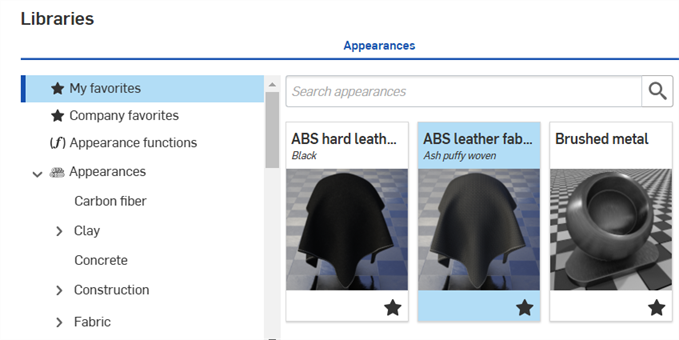
These folders are not visible if they do not contain any Appearances. By default, you do not see them listed in the Appearances library's folders list.
An appearance can be placed in both folders.
To add an Appearance to the My favorites or Company favorites folder:
-
Locate an Appearance you would like to add to the My favorites or Company favorites folder.
-
Right-click on the Appearance and select Add to favorites or Add to company favorites:
-
The Appearance is now located in the My favorites or Company favorites folder at the top of the Appearances library's folders list. Favorite Appearances display a star icon (
 ) at the lower right corner of their thumbnail.
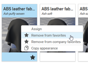
To remove an Appearance from a favorites folder, right-click on it and select Remove from favorites or Remove from company favorites:
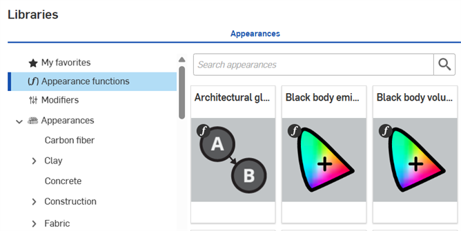
Functions are a special type of appearance that perform a specific action on a part's appearance parameter. When a scene is created, every part has a default set of appearance parameters, viewable in the Appearance panel on the right.
All functions are located in the top-level Appearance functions folder. Additionally, functions are indicated by a function icon (![]() ) at the top left corner of the Appearance thumbnail:
) at the top left corner of the Appearance thumbnail:
Tips
-
Some functions cannot be assigned to parts directly. If the right-click context menu options are unavailable from the appearance thumbnail, or the context menu does not open when the appearance thumbnail is dragged and dropped on the part in the scene, this indicates the appearance is a function.
-
See Appearance library - Functions for a complete list of all functions and a short description of each.
-
Some functions can only be applied to parameters in the Selection panel, and depend on what is selected in the Scene list.
-
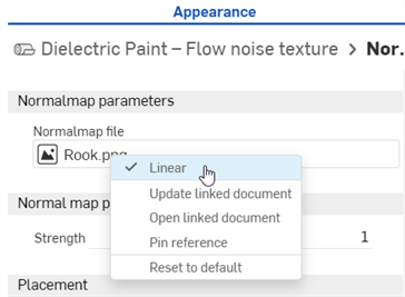
For the Normal map — texture function, texture resources can optionally be treated as containing linear color data. When the texture represents something other than a color (for example a tangent space normal map or scalar data such as roughness) then it should be treated as linear to ensure the color data is correctly processed.
For normal map textures specifically, the Linear option is automatically selected to ensure valid results. For other parameters you can choose how you want to interpret the colors using the Linear options on the context menu for the texture resource (see below):
-
To apply an Appearance function to an Appearance parameter while the Appearances library is in the right panel, drag the Appearance function on top of the Appearance panel icon and hold until it opens. Then drop the Appearance function on the parameter in the panel.

Dragging the Bump map Appearance function over the Appearance panel icon (left). The Appearance panel opens (middle). While still holding, drag the Bump map Appearance function on top of the Bumps parameter in the Appearance panel (right).
To apply a function to the part's Appearance parameter:
-
Select the part in the Scene list or graphics area. The Appearance panel displays the part's default Appearance parameters.
-
Select the Appearance functions folder In the Appearances library
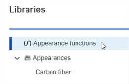
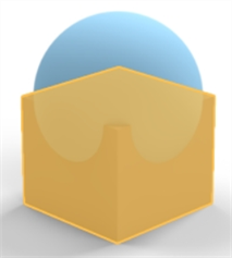
Locate the Checker pattern — 3D texture and Checker texture bump map functions. They are both used in this example. The lower box part in the following model is used for reference:
-
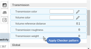
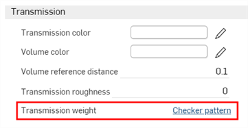
Drag the Checker pattern — 3D texture function over the Appearances panel. Before dropping, notice that many of the Appearance parameters are highlighted in blue. This indicates this function can be applied to any of these parameters. The function is applied to the parameter beneath the mouse cursor. Drop the parameter on the Transmission weight parameter in the Transmission submenu:
-
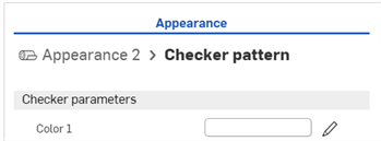
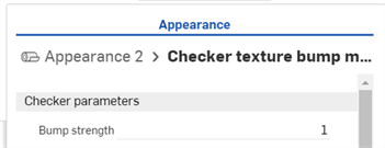
The texture function is applied and automatically opens in the Appearances panel. This is verified by viewing the hierarchical breadcrumb trail at the top of the Appearances panel (shown in the first image below). Click on the Appearance 2 link in this breadcrumb trail, and the Appearance for the part opens, where the link to the texture function next to the Transmission weight parameter is displayed (shown in the second image below).
-
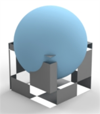
The texture function acts as a mask for light transmission through the part (the checker texture is the function applied to the Transmission weight parameter of the part's Appearance). Anywhere the checker pattern is white, light shows through. Anywhere the checker pattern is black, the base part color shows through. The checker pattern is the part's light transmission mask:
-
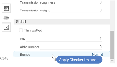
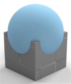
Alternatively, drop the Checker texture bump map function on the Bumps parameter in the Appearance panel's Global submenu. The Bumps parameter is the only one to turn blue, indicating this parameter is the only one that accepts the Checker texture bump map function:
-
The Checker texture bump map function is applied to the Bumps parameter, shown below:
See Add a bump texture and Add a custom bump texture for more information.
The next example applies an Invert color function to the Part's base color. Apply this method to any appearance color parameter, and use it to invert the color.
-
Select the part. In this example, the sphere is selected.
-
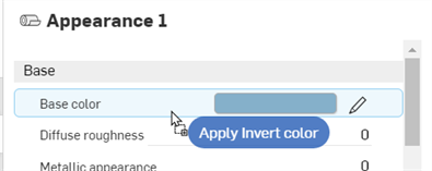
Drag and drop the Invert color function on the Base color in the part's Base submenu on the Appearance panel:
-
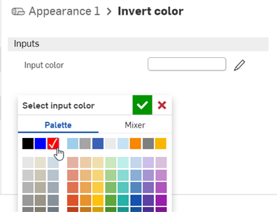
The Invert color function opens under the Appearance panel. Click the Input color swatch and select a color. The inverse of that color is used for the Part's base color. In the following example, selecting red creates a cyan base color, since cyan is the inverse of red:
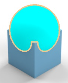
This example uses the Surface blender function to blend between two surface appearances. Once completed, an additional function (Gradient3-color/position texture) is applied to the first function's parameter (the Surface blender's Blend weight). This shows how to build one function on top of another function.
-
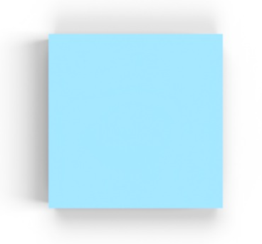
Select the part in the Scene list. In this example a square box is selected and viewed from the top plane. For reference, the box dimensions are .5 m length x .5 m width x .5 m height:
-
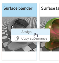
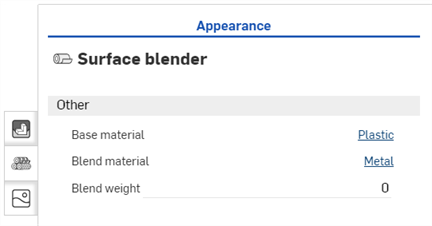
In the Appearance library, search for Surface. Right-click on the Surface blender thumbnail and click Assign (shown in the first image below). The Global submenu in the Appearance panel displays the Surface blender function parameters (second image below):
-
Base material - The appearance on which the blend is based.
-
Blend material - Blend appearance surface properties.
-
Blend weight - Blend weight or mask texture.
-
-
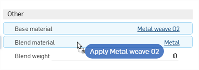
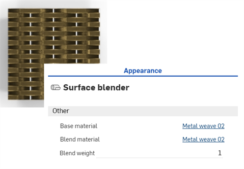
Search for the Metal weave 02 - brass steel Appearance and drag and drop the thumbnail on the Base material parameter (shown in the first image below). Then search for the Metal weave 02 - copper pure Appearance and drag and drop the thumbnail on the Blend material parameter (shown in the second image below). Adjust the Blend weight to 1. This blends the colors between the two appearances (the Base material and the Blend material). The result is shown in the third image below:

-
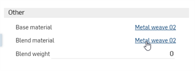
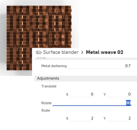
Click on the blend material link to open its parameters in the Appearance panel (shown in the first image below). Rotate the material 90 degrees in the Adjustments submenu. The horizontal pattern is now combined with the newly rotated vertical pattern (shown in the second image below). This better visualizes the blend between the two:
-
To return to the parent Surface blender layer, click the Surface blender link in the breadcrumb trail at the top of the Appearance panel:
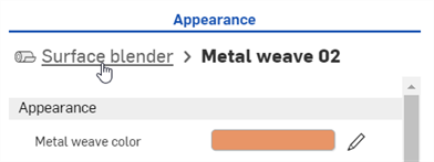
The above procedure works to blend any two surface appearances together. Building on the above procedure, a gradient function is applied to the Surface blender function's Blend weight parameter to blend between the two appearances.
-
Open the 2 Appearances and change their Weave and bar colors to the following: red and green for the Base material, and blue and yellow for the Blend material. This better visualizes the blends in subsequent steps. The result is shown in the second image below:
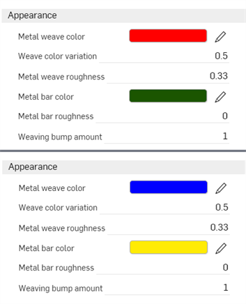
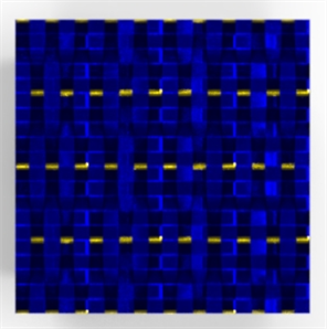
-
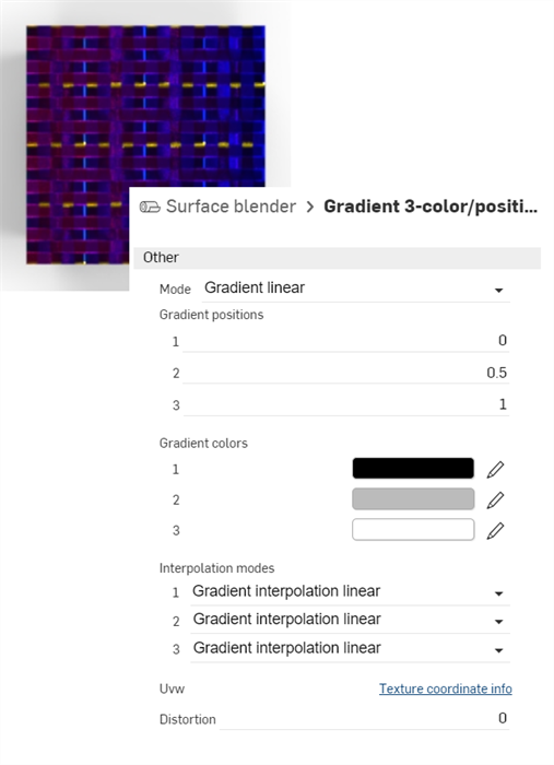
Return to the parent Surface blender layer. Search for the Gradient 3-color/position texture function in the Appearance library, and then drag and drop the thumbnail on the Blend weight parameter.
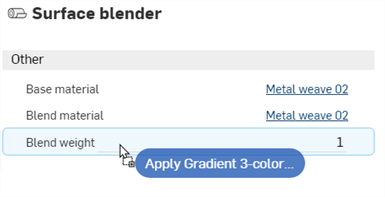
-
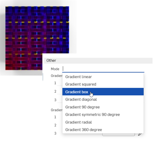
The Gradient 3-color/position texture function is now applied to the Blend weight of the Surface blender function's parameter. The gradient is used as a mask between the Base material red and green colors (starting on the left) and the Blend material's blue and yellow colors (ending on the right). Where the gradient is black, the Base material shows through. Where the gradient is white, the Blend material shows through.
Altering the Gradient parameters produces a variety of gradient results that blend between the two appearances. For example, the image below displays the Mode: Gradient box option (shown in the second image below):
Tips
-
To blend between two colors, use the Blend colors function and apply it wherever a color parameter is available in the Appearance or Selection panel. Using the blend colors function opens access to layer blending modes that are found in applications like Adobe Photoshop and GIMP (darken, screen, multiply, overlay, and others).
-
To blend between two bump textures, use the Blend normals function and apply it wherever the Bumps parameter is available in the Appearance or Selection panel.
-
Instead of the Gradient 3-color/position texture function, use any other texture functions, such as the Checker pattern or Bump map — Perlin noise texture to blend between the two appearances.
-
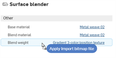
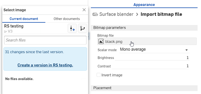
Add a custom texture to blend between the two appearances. Drag and drop the Import bitmap file function on the Blend weight parameter (shown in the first image below), and then Click the Bitmap file to open the Select image dialog, where you can load the custom texture (shown in the second image below):
For a tech tip on blends, see Using textures and blends in Render Studio.
This procedure explains how to add a specific volume and the Volume coefficient function to a part in the scene. Volume is added as an appearance to the part, while the volume coefficient is a function added to the Absorption coefficient parameter of the appearance.
For this example, a light-emitting ship object is placed in an underwater scene where the water acts as the volume.
-
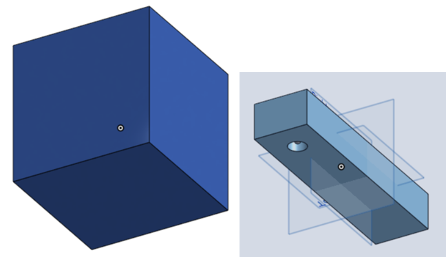
To add volume, the scene must be encompassed by the volume itself. Model a part that surrounds the ship object on all sides, and is large enough to provide sufficient space.
For reference, the surrounding box in this example is 5 m cubed. The rectangular "ship" is 0.6 m length by 0.075 m wide by 0.05 m height. A hole is placed at the front bottom of the rectangle with a diameter of 0.025 and is 0.03 m deep so it does not protrude all the way through the rectangle. Finally, a sphere with a radius of 0.004 m is created inside the hole, which is used as a light source. Each entity (part) is referenced as volume, ship, and light source below.
-
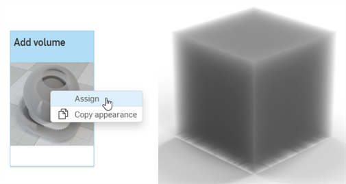
In the Scene list, select the volume part. Search for volume in the Appearances library, right-click on the Add volume thumbnail and select Assign from the context menu. This results in a thick volumetric appearance applied to the surrounding part:
-
Base material - The material onto which the volume is applied. Default is transparent.
-
Absorption coefficient - The probability density (per meter in world space) of light being absorbed by the participating medium. Default is white (R: 255; G: 255; B: 255). A higher absorption value makes the medium darker, due to more of the light being absorbed as it passes through the medium.
-
Scattering coefficient - The probability density (per meter in world space) of light being scattered from its current direction. The default is white (R: 255; G: 255; B: 255). A higher scattering value distributes more of the light throughout the medium.
-
Directional bias - Influence of light direction on scattering. A value of 0 specifies isotropic scattering, 1 forward scattering, and −1 back scattering. The default is 0.
-
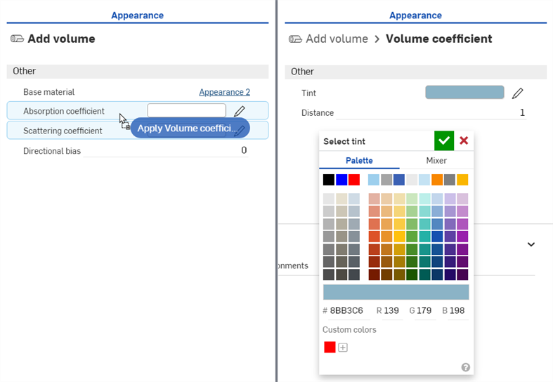
In the Appearances Library > Appearance functions folder, locate, and then drag and drop the Volume coefficient function on top of the Absorption coefficient parameter in the Appearance panel (shown below left). Then adjust the Tint parameter to R: 139; G: 179; B: 198 (shown below right). This creates a volume of water that contains the ship.
-
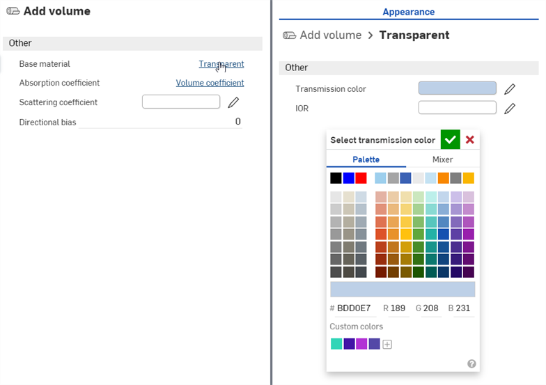
Click the Transparent link next to the Base Material parameter, and adjust the Transmission color to R: 189; G: 208; B: 231, as shown below:
-
At the top of the Appearance panel, click the Add volume link to return to the volume parameters. Set the Directional bias to 0.7. This lightens the scene, so the ship is visible inside the water:

-
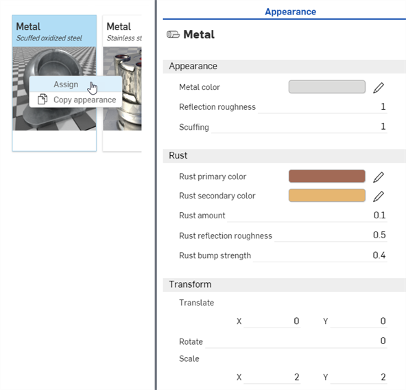
In the Scene list, deselect the volume part and select the ship part. Locate the Metal — Scuffed oxidized steel Appearance in the Appearance library, right-click on the thumbnail and select Assign from the context menu (shown below left). In the Appearance panel, adjust the following parameters: Scale: X: 2 by Y: 2; Rust bump strength: 0.4; Rust amount: 0.1; Rust reflection roughness: 0.5; Reflection roughness: 1:
-
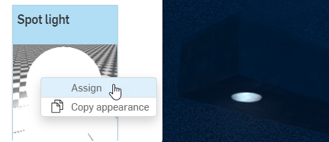
In the Scene list, deselect the ship part and select the light part. Locate the Spot light Appearance in the Appearance library, right-click on the thumbnail and select Assign from the context menu (shown below left). Zoom into the ship to view it from the bottom up. The light is illuminated but is very faint (shown below right):
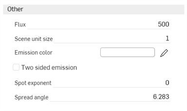
Spot light parameters are:
-
Emission color - Light color. This is rescaled such that it does not influence the luminous flux. The default is white (R: 255; G: 255; B: 255).
-
Flux - The total luminous flux (in lumen) the light emits. The default value is 500. It is generally required to increase this value, depending on the scene.
-
Scene unit size - Convert m to scene unit. For example, if 1 in the scene is one foot (US customary units), then the scene unit size is 0.30481. The default value is 1.
-
Spot exponent - The higher the exponent, the more focused the emission. The default value is 0.
-
Spread angle - Spread angle in RAD. Hard limit for the spot spread. The default value is 6.283.
-
Two sided emission - If enabled, emission occurs on the front and backside of the geometry. The default is disabled.
-
-
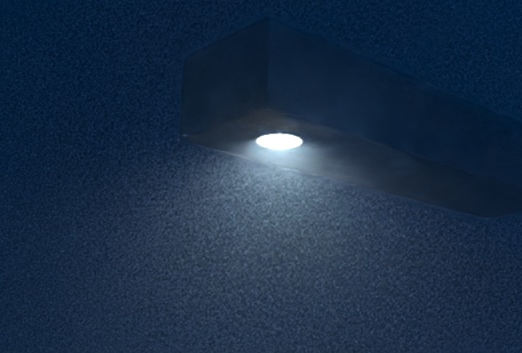
Set the Flux to 20000 and Scene unit size to 0.8. The light now emits a higher intensity light, and is diffuse and unfocused:
-
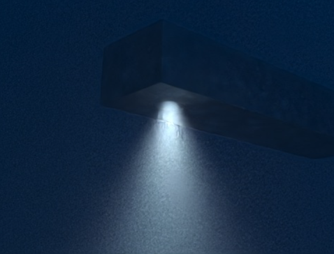
To focus the light to a narrower beam, set the Spot exponent to 15 and Spread angle to 2.5:
-
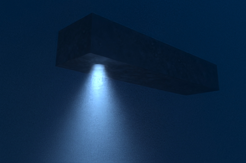
To have the light color blend in with the water, alter the Emission color to R: 157; G: 189; B: 226. Bear in mind that any of these parameters can be adjusted to different specifications. This is one variation on the scene render:
The following outlines the Add volume Appearance panel parameters:
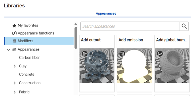
Modifiers are a special type of appearance that are used to modify other appearances. Drag and drop a modifier appearance on the part or face in the scene, or drag and drop it on the Appearance parameter in the panel. These modifiers do not overwrite the prior appearance. Instead, the modifier is associated to the Base material parameter of the new modifier appearance.
To instead overwrite the prior appearance with the new modifier appearance, select the part or part face in the Scene list or graphics area, right-click on the modifier appearance thumbnail in the Appearance library and select Assign from the context menu.
All modifiers are located in the top-level Modifiers folder. Additionally, modifiers are indicated by a modifier icon (![]() ) at the top left corner of the Appearance thumbnail:
) at the top left corner of the Appearance thumbnail:
Transforming an Appearance is similar to transforming a part, however, only the Appearance is transformed. The part remains static. This example uses a wood table. The wood appearance is transformed to make the table look more realistic.
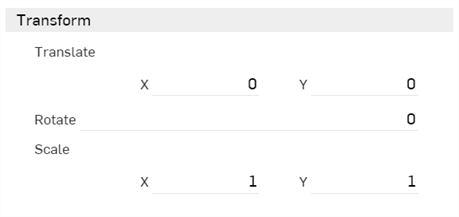
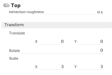
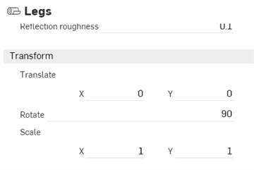
Appearances generally have a transform submenu in the Appearance panel, with x and y axis values for Scale and Translate, and a degree value for Rotation, as shown below:
-
Translation - Moves the selection along the x and y axis, according to the origin point of the selection. Measurement units are in meters, and are negative or positive numbers.
-
Rotation - Rotates the angle of the texture about the center point of the selection's z axis, from -360 to +360 degrees.
-
Scale - Scales the selection up (larger) or down (smaller), along the x and y axis, according to the center point of the selection. Measurements are based on the selection's original size. For example, a Scale of 1.000 x by 1.000 y means that the scale is 100% of the part's original size. Fractional numbers from 0.001 to 1 reduce the size of what is selected.
-
Create an Assembly of a table top and four legs, so there are five assembled parts.
-
Create a Render Studio scene and insert the table Assembly.
-
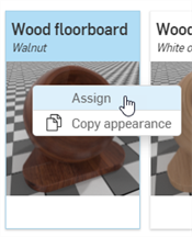
Select the table top in the Scene list. Search Floorboards in the Appearance library. Right click on the Wood floorboard — Walnut Appearance and select Assign from the context menu. The Appearance is applied to the table top:
-
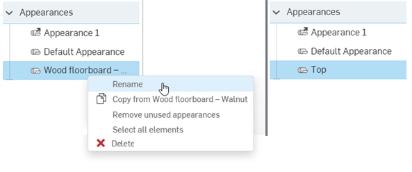
In the Scene list, under Appearances right-click on the Wood floorboard Appearance and select Rename from the context menu. Rename the Appearance "Top". This also renames the Appearance in the Appearances panel on the right.
-
In the Scene list, deselect the table top, and multi-select (Ctrl/Cmd+Select) the table legs. Right click on the Floorboards - Walnut and select Assign from the context menu. The appearance is applied to all four table legs.
-
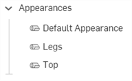
In the Scene list, under Appearances right-click on the Wood floorboard Appearance and select Rename from the context menu. Rename the Appearance "Legs".
-
Click on the Top appearance thumbnail to select it. In the Appearance panel's Transform submenu on the right, enter a scale of 3 x 3. This removes the floorboard grooves by translating the appearance pattern larger than the table:
-
Click the Legs Appearance thumbnail in the Appearance library. Enter a Rotation measurement of 90 degrees in the Appearance panel's Transform submenu. This creates vertical planks of wood along the table leg appearance. Since the Legs appearance in the Scene appearances folder is associated with all four legs, they are all transformed simultaneously as a group:
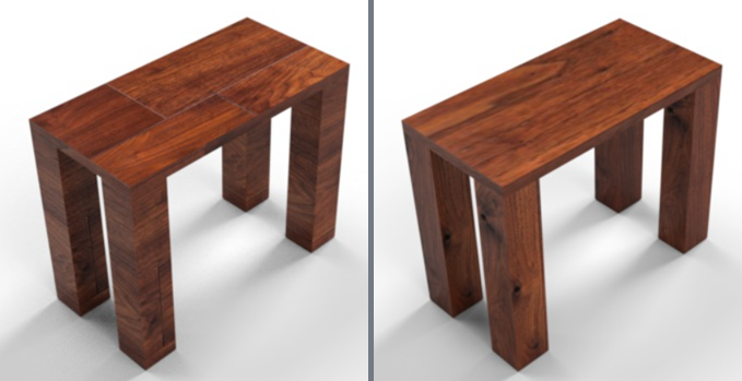
The Table model with default Walnut - Floorboards appearance (left), and after transforming the appearances (right).
Adjustments may not always yield the same results shown in the sample image here, especially with Transform options, which depend largely on model size. The Appearance may require a scale larger or smaller than X: 3 by Y: 3.
Optionally, for more granular control of Appearance transformations, apply the same or different appearances to each part face and then transform each face appearance separately. To do this, click on the arrow to the left of the part name in the Scene list to expand all the part's faces.
When an appearance is applied to a part or face in a scene, it is placed in the Appearances section at the bottom of the Scene list. This helps keep track of appearances used in the scene. Apply the same appearance to multiple parts. When any part or face that uses the appearance is selected, and its appearance edited in the Appearances panel, all other parts and faces using the appearance are updated simultaneously. There is no need to individually update each part or face appearance.
-
Add an appearance to a part or face. In the image below, a blue cloth material appearance is added to one of the shoes.
-
Rename the appearance. This helps to locate the appearance in the Scene list later, especially if the scene is complex, with many appearances.
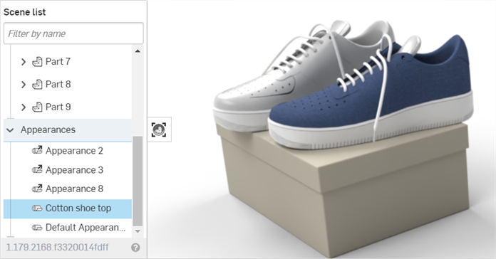
-
Locate the Appearance in the Scene appearances folder in the Appearances library, and assign the appearance to as many other parts or faces in the scene:
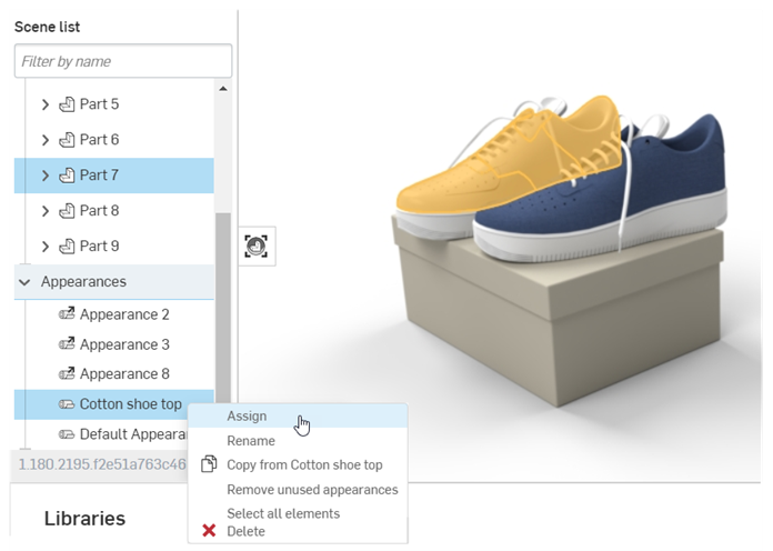
-
Edit the Appearance using the Appearances panel. For example, in the image below, the color of the shoe fabric is changed to gray. Notice that both shoes are updated with the new color attribute, even though only one shoe is selected:
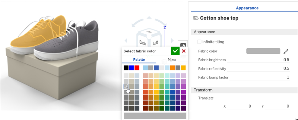
Apply a texture to one of the part's appearance parameters. This procedure explains how to apply a texture to the part's Diffuse roughness parameter.
-
In the Scene list or graphics area, select the part.
-
Expand the Base submenu in the Appearance panel, if it is not already expanded.
-
In the Appearances library, select the Appearance functions folder.
-
Locate the Checker pattern function, then click and drag it from the Appearances library and drop it on top of the Base submenu's Diffuse roughness parameter in the Appearance panel on the right.
-
The texture is applied and automatically opens in the Appearances panel. This is verified by the hierarchical breadcrumb trail at the top of the Appearance panel. Adjust the Checker pattern's parameters to different specifications using the submenus in the Appearance panel:
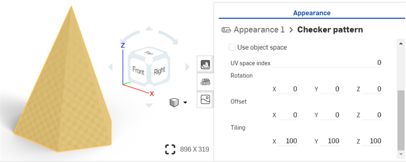
-
Click the Appearance 1 breadcrumb link at the top of the Appearances panel (shown in the first image below) to return to the part's Appearance panel. To edit the texture again, click its link next to the Diffuse roughness parameter (shown in the second image below):
Before dropping the texture, notice that many of the Appearance parameters are highlighted in blue. This indicates the texture can be applied to any of these parameters. Drop the thumbnail on the parameter of choice. See Using Appearance functions for more information.
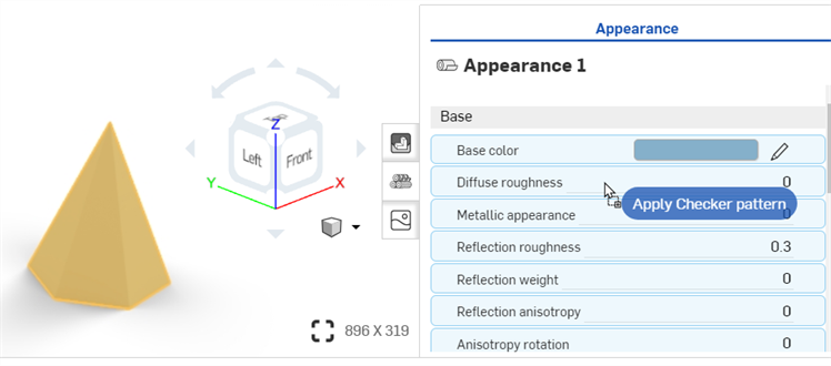

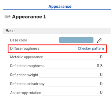
This procedure explains how to apply a custom image (PNG or JPG, for example) as a texture to a face or part appearance's Base color parameter. You can, however, modify this procedure to apply the texture to a number of other appearance parameters, as required.
An alternative way to apply a custom image as a texture is to use the appearance parameter's context menu in the Appearance panel. See Applying a texture to a parameter.
-
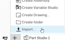
If your texture image is not already imported into your document, click the Insert new tab icon (
 ) and select Import:
-
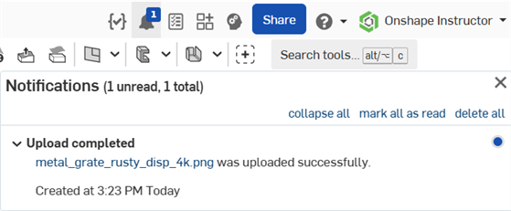
You will receive a notification when the file is imported:
-
In the Scene list or graphics area, select the faces and/or part.
-
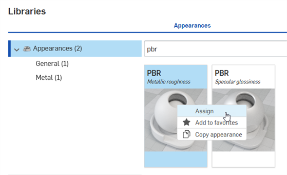
Locate the PBR - Metallic roughness appearance in the library. Right-click on it and select Assign from the context menu:
-
From the Appearance panel, set some basic parameters on the appearance, such as Metallic, Brightness, Opacity, and more, to your requirements.
-
Locate, then drag and drop the Import bitmap file - Bitmap texture function on the Base color parameter of the PBR - Metallic roughness appearance in the Appearance panel:
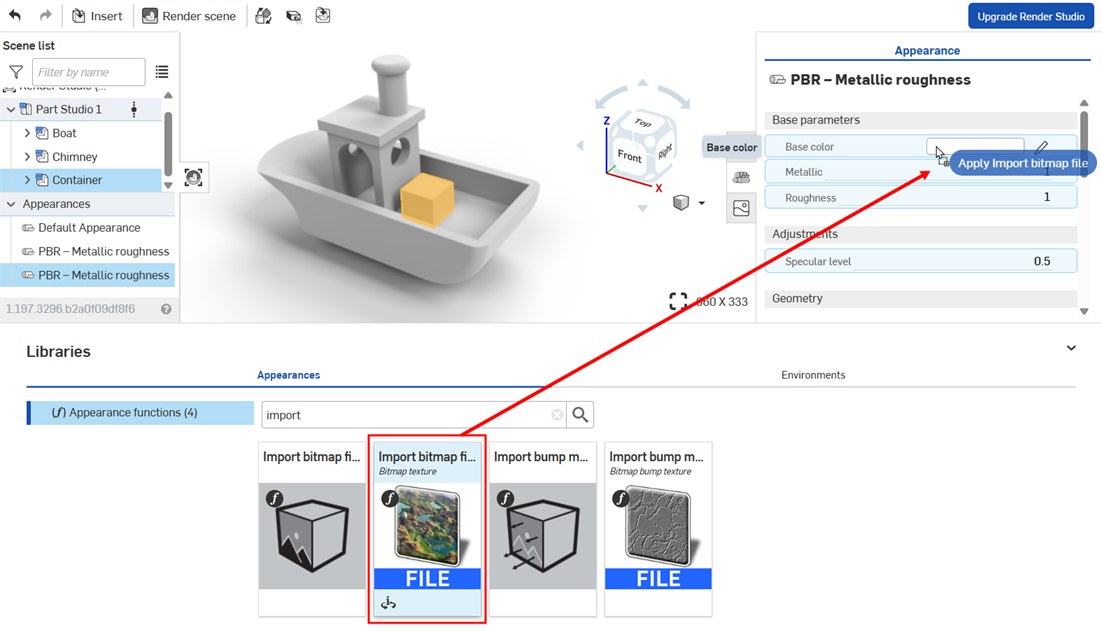
Before dropping the texture, notice that many of the Appearance parameters are highlighted in blue. This indicates the texture can be applied to any of these parameters. Drop the thumbnail on the parameter of choice. See Using Appearance functions for more information.
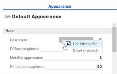
Alternatively, right-click on the parameter and select Use bitmap file, then select the file you imported to apply it to the parameter:
-
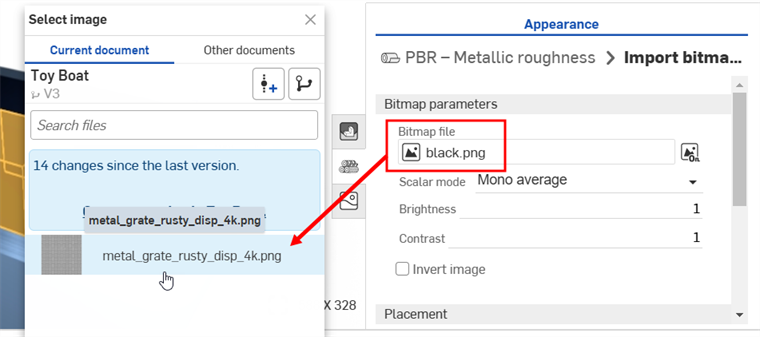
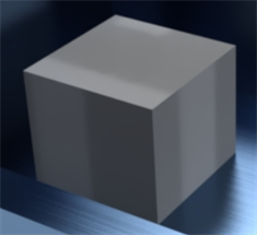
Click the default black.png Bitmap file and select the texture image you imported into your document earlier (shown in the first image below). The texture is applied to the selected faces and/or part (shown in the second image below):
If you import the texture after you have already created the Render Studio tab, you will need to create a version of your document in order to access the Texture from the Select image dialog.
-
Modify the Rotation, Offset, and Tiling of the texture on the image to your specifications.
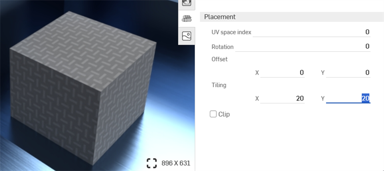
Setting the Tiling to x: 20; Y: 20
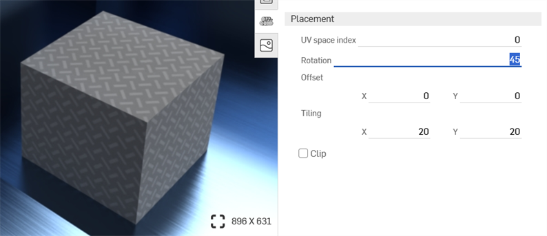
Setting the Rotation to 45 degrees
-
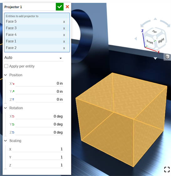
Click the Projector icon (
 ) on the toolbar to open the Projector dialog.
 -
In the Entities to add projector to, select the faces and/or part to which you applied the texture.
-
Select the Position, Rotation, and Scaling options to your specifications.
A bump texture (or bump map) simulates a part's surface texture. Normal maps are a specific type of texture where bump details (wrinkles, grooves, patterned divots, and the like) are added to the model. When light is reflected off the surface, real geometry is simulated.
A bump texture is not applied directly to the part. It is applied to the part appearance's Bumps parameter.
-
Select the part in the Scene list or graphics area.
-
Expand the Global submenu in the Appearance panel, if it is not already expanded.
-
In the Appearances library, select the Appearance functions folder.
-
Locate the Checker texture bump map function, then click and drag it from the Appearances library and drop it on top of the Bumps parameter in the Appearance panel on the right.
-
Once applied, adjust the bump texture parameters using the Appearance 1 > Checker texture bump map panel submenus:
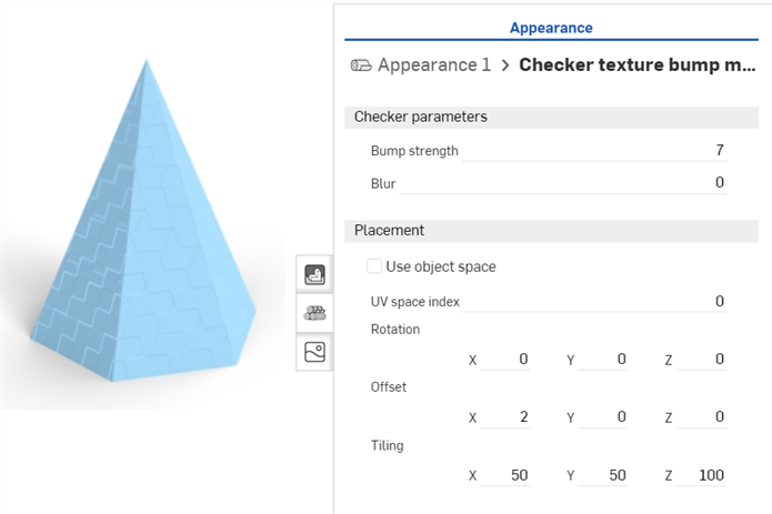
-
Click the Appearance breadcrumb link at the top of the Appearance panel (shown in the first image below) to return to the part's Appearance panel. To edit the bump texture again, locate it in the Global submenu and click on its link (shown in the second image below):

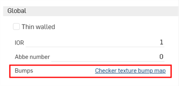
Before dropping the bump texture, notice that only the Bumps parameter is highlighted in blue. This indicates the bump texture can only be applied to this parameter. See Using Appearance functions for more information.
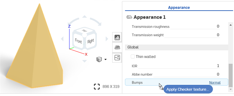
A bump texture (or bump map) simulates a part's surface texture. Normal maps are a specific type of texture where bump details (wrinkles, grooves, patterned divots, and the like) are added to the model. When light is reflected off the surface, real geometry is simulated.
A bump texture is not applied directly to the part. It is applied to the part appearance's Bumps parameter.
-
Select the part in the Scene list or graphics area.
-
Expand the Global submenu in the Appearance panel, if it is not already expanded.
-
In the Appearances library, select the Appearance functions folder.
-
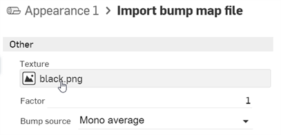
Locate the Import bump map file function, then drag and drop it on top of the Bumps attribute on the Global submenu.
-
In the Appearance panel, click the Bitmap file (black.png). This opens the Select image dialog:
-
Do one of the following:
-
Select a bump map file from the Current document
-
Click Other documents to locate a file in another Onshape document
-
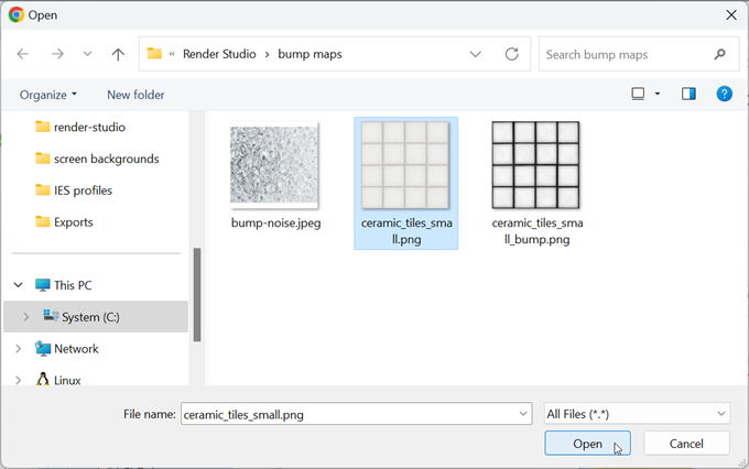
Click the Import link at the bottom of the dialog to locate a bump map file (.jpg or .png) from your computer. When selected, click the Open button:
Once the notification indicates the upload is complete, you will not yet see the image in the Select image dialog. This is because the Render Studio scene is a snapshot of the part, Part Studio, or Assembly at the time of import, and this image is brought into the Onshape document post-import. A new version is now required, in order to update the scene. Click the Create a version in [Document name] link in the Select image dialog:
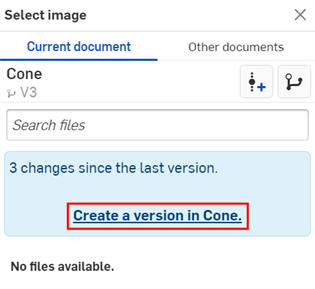
The Create version dialog opens. Enter the version information and click the Create button.
-
-
Once the new version is created, the .ies file is located in the Select light profile. Click it to select it:
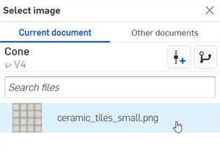
-
Once selected, the file is loaded into the Bitmap file field. Use the Bitmap and Placement submenus to edit the bump texture parameters:
-
Tiling - Control the scale of the texture on the part. Larger numbers reduce the texture size (more tiles), while lower numbers increase the size of the texture (fewer tiles).
-
Clip - If enabled, the texture does not repeat and anything outside the texture shows as flat.
-
Offset - Control the position of the texture on the part
-
Rotation - Control the rotation of the texture on the part, in degrees.
-
Bump mode - Define how the texture is evaluated to create the bumps.
-
Bump strength - Control the intensity of the Bump map tiling.
Alternatively, use the Import bitmap file function (shown in the red box below) for more complex texture editing capabilities. Complex graphs of texture placement functions are connected to file_texture maps.
Before dropping the bump texture, notice that only the Bumps parameter is highlighted in blue. This indicates the bump texture can only be applied to this parameter. See Using Appearance functions for more information.
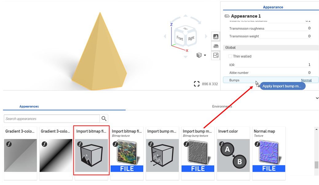
If you don't see the Create version link in the Select image dialog, click the Create version button (![]() ) on the Document panel to open the Create version dialog. Create the new version. Close and reopen the Select image dialog. The imported image should now be available.
) on the Document panel to open the Create version dialog. Create the new version. Close and reopen the Select image dialog. The imported image should now be available.
See Importing files for more information about uploading files.
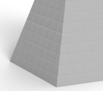
There are several appearances devoted to adding and emitting light from a part, surface, or face in a scene. Which light appearance is used depends on the light source and how the scene in question should be lighted. Light emission appearances are outlined below:
| Light Appearance Name | Description |
| Add emission | Adds emission to a material. See Add a light using the Add emission Appearance for more information. |
|
Add thermal emission |
Adds emission to a material, Color is based on a "color temperature". See Add a thermal emission Appearance for more information. |
| Light source emitter — 1900k candle | AEC - Lights - Candle 1900k Emitter. See Additional light examples for more information. |
| Light source emitter — 7000k cool white emitter | AEC - Lights - Cool White 7000k Emitter. See Additional light examples for more information. |
| Diffuse area light | Material for an area light with a diffuse emission everywhere. See Additional light examples for more information. |
| Display screen | Design - Lights - Display Screen (Illuminated screen for displays). See Display screen for more information. |
| Light source emitter — 5000k fluorescent | AEC - Lights - Fluorescent 5000k Emitter. See Additional light examples for more information. |
| Light source emitter — 3000k halogen | AEC - Lights - Halogen 3000k Emitter. See Additional light examples for more information. |
| IES light | 2 Appearances: (1) Material for a light with Ies defined distribution characteristics and (2) IES profile driven light material, scaling the original data to yield the specified flux. See Add a custom IES light profile for more information. |
| Light source emitter — 4000k natural white | AEC - Lights - Natural White 4000k Emitter. See Additional light examples for more information. |
| Photometric light | Material for a light source driven by IES photometric profile. Note that for profiles using absolute measurements (e.g., those for LED) the multiplier argument should be set to 1.0. See Additional light examples for more information. |
| Spot light | 3 Appearances: (1) Material for a light with a shaped emission characteristic, (2) Spot light material with global (object orientation aligned) distribution, and (3) glTF 2.0 spot light source. See Add a spot light and reflective surface and Add Volume and Volume coefficient for two spot light examples. |
| Light source emitter — 2700k warm white | AEC - Lights - Warm White 2700k Emitter. See Additional light examples for more information. |
In addition to the above light appearances, add a bloom filter via the Scene panel.
This is a simple way to add a light emission to any part in the scene:
-
In a Part Studio or Assembly, create a part used as a light source and add some walls around the part. In this example, a light bulb is modeled, with some side walls and a floor:
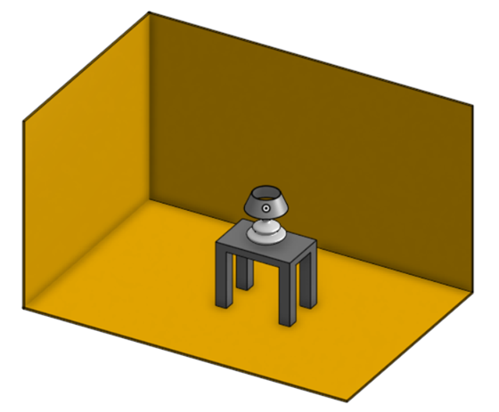
-
Select the walls in the Scene list.
-
In the Appearance library, search for apply. Right-click on the Apply clear coat Appearance and click Assign from the context menu. This adds reflective surfaces off which the light emission reflects:
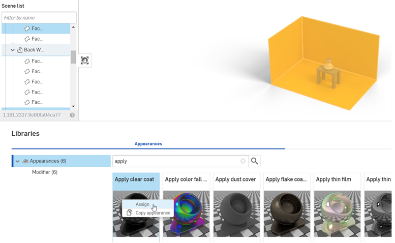
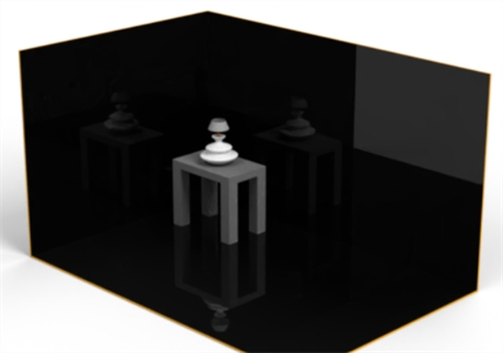
-
In the Scene list or graphics area, select the bulb's glass cover.
-
In the Appearance library, locate the Thin glass Appearance. Right-click on its thumbnail and click Assign from the context menu.
In the example below, a metal Appearance is assigned to the screw base, and a copper Appearance to the bottom bulb connector. Finally, the lamp, lamp shade, and table are removed, to better showcase the bulb's emission.
-
In the Scene list, select the part used for the filament inside the bulb (shown in the left image below).
-
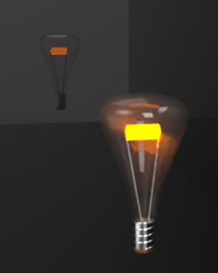
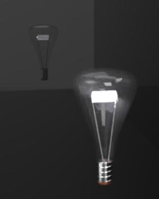
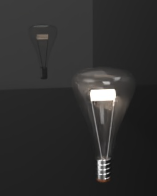
In the Appearances library, locate the Add emission Appearance. Right-click on its thumbnail and click Assign from the context menu (shown in the middle image below). The filament appears dark at first (shown in the right image below):
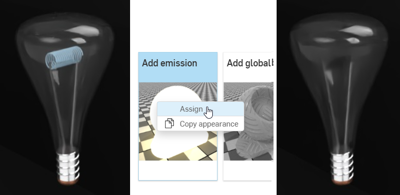
Appearance options are:
-
Base material - The material to which the emission is added. The default is diffuse.
-
Intensity - The brightness of the light source. The default value is 1000.
-
Color - The light emission color. The default is white (R: 255; G: 255; B: 255).
-
Unit for emission - The physical unit of "Intensity". The default is Lumen m2. Other options are Lumen, Candela, and Nit.
-
Unit scale - The modeling unit to meter conversion factor. The default value is 100.
-
-
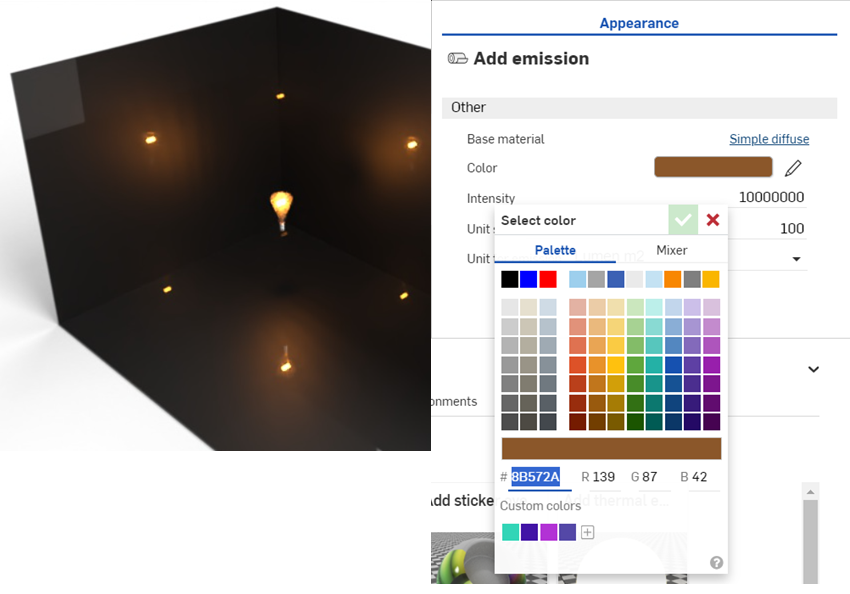
In the Appearance panel, adjust the emission Intensity upward. Keep in mind this value depends largely on the scene dimensions. For reference, the dimensions of the room created below are 2.43 m length by .97 m wide by .84 m height. The Intensity value is set to 10000000. This creates an emissive white light:
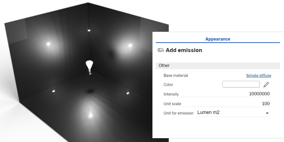
-
Adjust the color to control the warmth or coolness of the light emission. The following example displays how the light emission changes when a new color is selected:
-
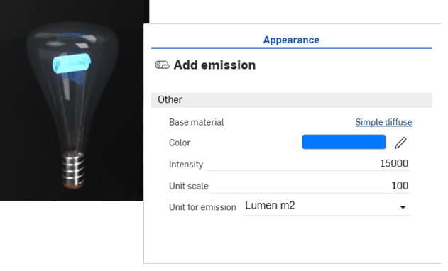
Zoom into the bulb, decrease the intensity, and change the color to blue to create the emission shown below:
-
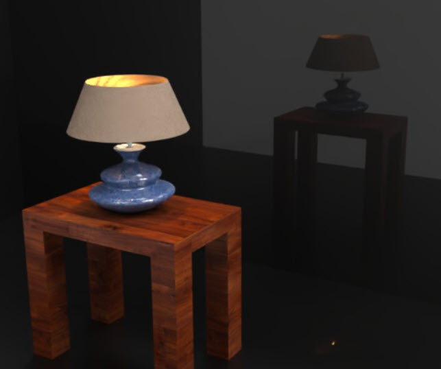
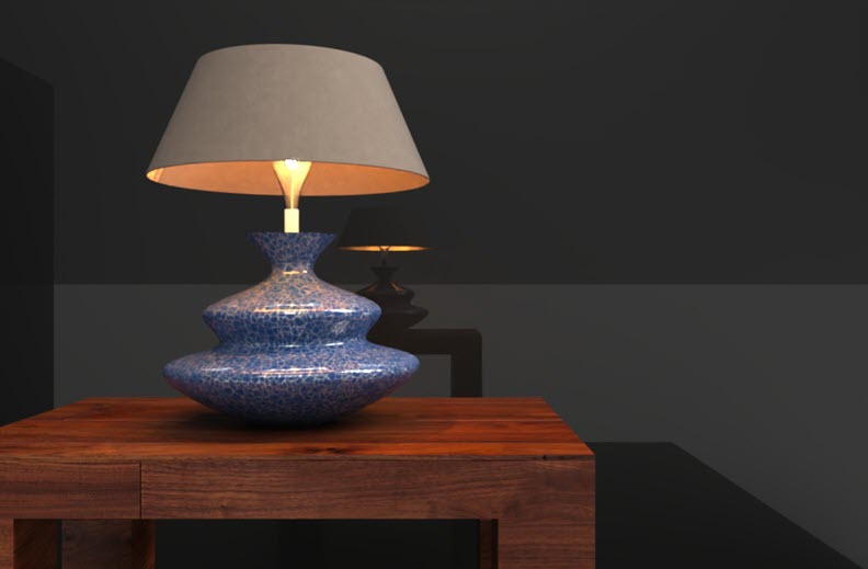
The final example shows how the light bulb is used in a completed scene, with the addition of a lamp and table. Note how the shade over the bulb redirects the light emission upward and downward, and dulls the emissions where the shade is set between the light source and the walls:
Similar to the Add emission appearance, the Add thermal emission appearance adds light to a modeled part, surface, or face. However, the light source is meant to act as a source of thermal heat. The Color parameter is replaced by a Temperature parameter, which is adjusted to define the type of heat source.
-
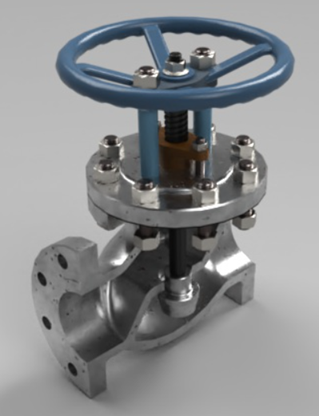
Once the part is modeled, create a scene from the Part Studio or Assembly. The example used here is a Valve assembly:
-
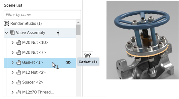
Select the part in the Scene list or graphics area. This is the part used as the thermal emission origin. In the example below, the gasket is used as the emission source:
-
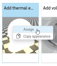
In the Appearances library, locate the Add thermal emission Appearance. Right-click on its thumbnail and click Assign from the context menu:
-
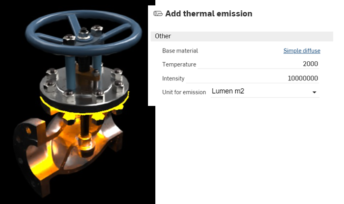
In the Appearance panel, adjust the Intensity upward. For this scene, the Intensity is set to 10000000. Then set the Temperature to 2000. This creates an orange-colored thermal emission:
-
Setting the Temperature value to 65000 changes the emission color to blue, which is used, for example, to indicate heat from a hydrocarbon source, such as butane or propane gas:
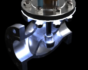
As a general guideline, values from 0 to 3500 are in the red-orange-yellow range, while numbers from 10000 upward are in the blue range. The default value of 6500 emits a white color.
IES light profiles describe the distribution of light from a lamp. This data is provided by many manufacturers so that designers can realistically render light within a room.
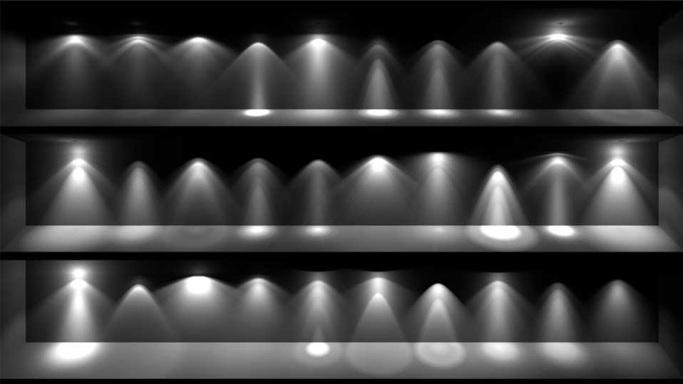
An example of several IES profiles.
Render Studio provides the ability to add an IES light profile to a light source.
-
Select the part or face in the Scene list or graphics area.
-
Search the Appearances library for Photometric. Right-click on the Photometric light thumbnail, and click Assign from the context menu. The example below is a living room with a very dark environment:
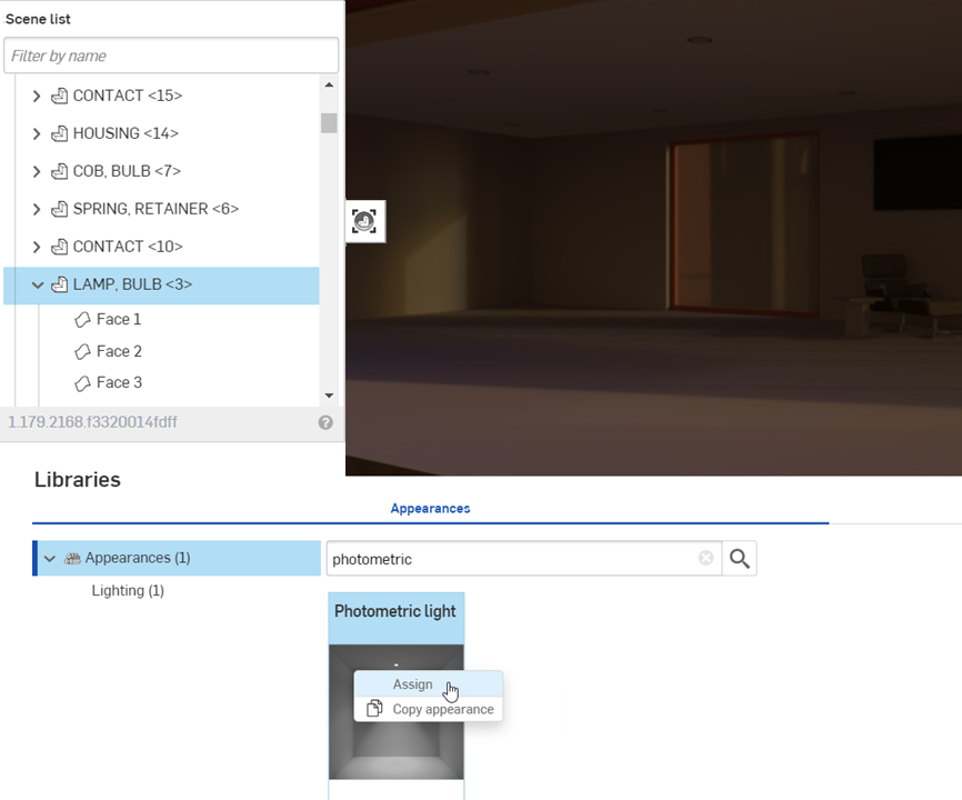
-
In the Appearance panel > Distribution submenu, click the IES file (downlight.ies). This opens the Select light profile dialog.
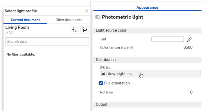
-
Do one of the following:
-
Select an IES file from the Current document
-
Click Other documents to locate an IES file in another Onshape document
-
Click the Import link at the bottom of the dialog to locate an IES file from your computer. When selected, click the Open button:
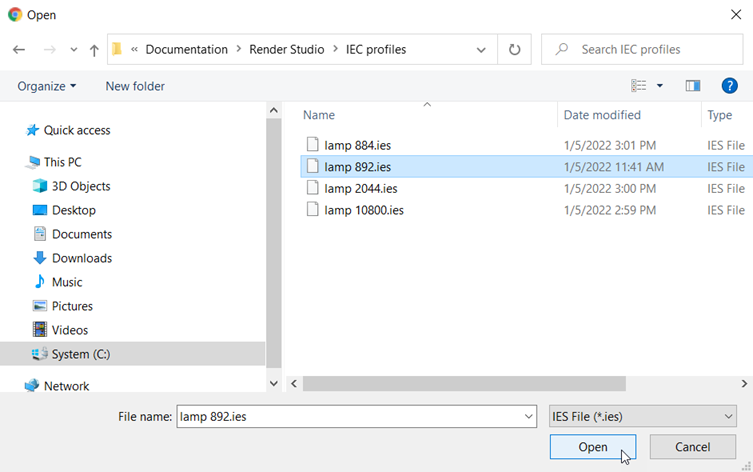
Once the notification indicates the upload is complete, you will not yet see the image in the Select image dialog. This is because the Render Studio scene is a snapshot of the part, Part Studio, or Assembly at the time of import, and this image is brought into the Onshape document post-import. A new version is now required, in order to update the scene. Click the Create a version in [Document name] link in the Select image dialog:
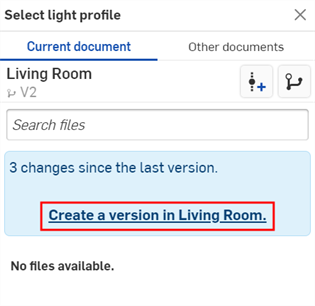
The Create version dialog opens. Enter the version information and click the Create button.
-
-
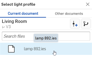
Once the new version is created, the IES file is located in the Select light profile. Click it to select it:
-
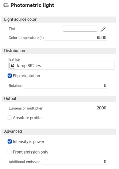
Once selected, the file is loaded into the IES file field:
-
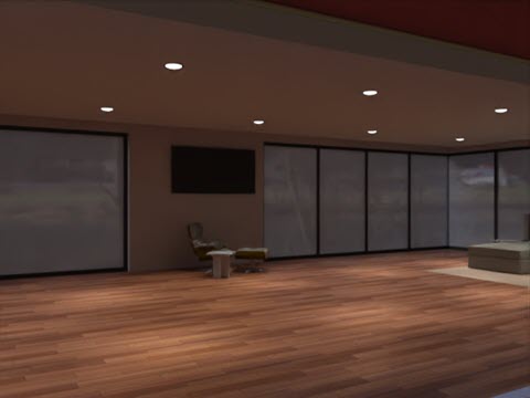
Edit the parameters in the Appearance panel submenus. For example, alter the Tint to change the light color, and increase the intensity of the light by adjusting the Lumens or multiplier. In the examples below, the IES profiles are applied to the recessed lights in the living room ceiling:
If you don't see the Create version link in the Select light profile dialog, click the Create version button (![]() ) on the Document panel to open the Create version dialog. Create the new version. Close and reopen the Select light profile dialog. The imported image should now be available.
) on the Document panel to open the Create version dialog. Create the new version. Close and reopen the Select light profile dialog. The imported image should now be available.
See Importing files for more information about uploading files.
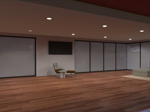
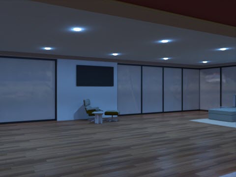
Below are two variations on the lighting. The first image uses an IES profile with a wider emission spread than the example above, while the second image uses an IES profile that emits a halo surrounding the bulbs. The Emission color is set to blue:
For a collection of free IES profiles, visit https://ieslibrary.com/en/home
The Display screen is a very specific type of appearance used to replicate an image on a television, computer, or other digital screen. Options are:
-
Image - Opens the Select image dialog, where you can locate an image to be mapped onto the display.
-
Repeat image - If enabled, the image repeats across the UV coordinates. If disabled, a single instance of the image displays across the UV coordinates. The default is enabled.
-
Intensity - The display emission intensity. The default value is 40. Note that when applying this appearance, the light source will most likely be black. Increasing the intensity to a higher value should yield a sufficient intensity to view the emission. This depends on scene size.
-
Screen roughness - Higher roughness values lead to bigger highlights and blurrier reflections. The default value is 0.2.
-
Translate - Controls the position of the image along the x and y axes.
-
Rotate - The Rotation angle of the image in degrees.
-
Scale - Scales the image size along the x and y axes. Larger numbers increase the size. Smaller numbers decrease the size.
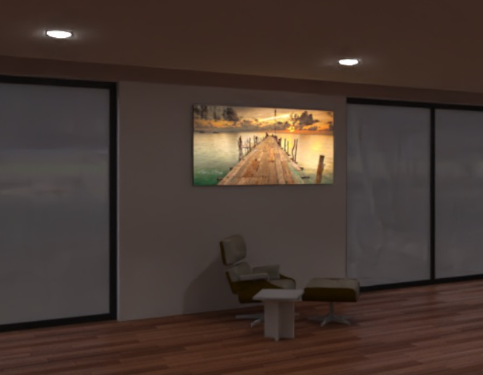
Display screen light example (applied to the front face of the wall screen)
Intensity: 200000
The following lights all use the same base Light source emitter parameters. Only the Color temperature value varies:
-
Color temperature - Color temperature, in Kelvin.
-
Lumens (flux) - The luminous flux, in lumens, the light emits. The default value is 1000.
-
Two-sided emission - If true, emission happens on the front and back sides of the geometry. The default is disabled.
|
1900k candle
|
7000k cool white
|
5000k fluorescent
|
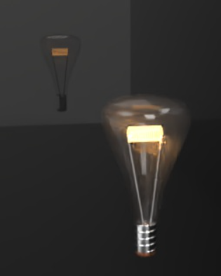
3000k halogen
|
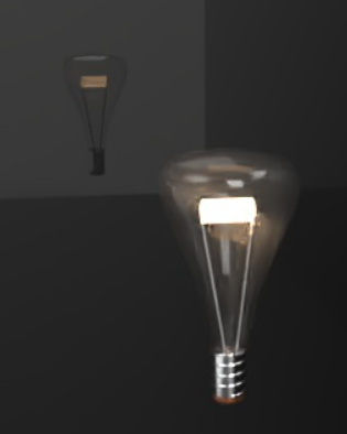
4000k natural white
|
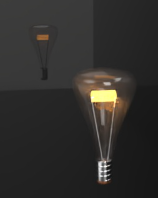
2700k warm white
|
The following are Diffuse area light options:
Diffuse area light:
-
Flux - The luminous flux (in lumen) the light emits in total. The default value is 500.
-
Scene unit size - Convert meter to scene unit. Examples: 1 in the scene is one foot: Scene unit size = 0.30481.0 in the scene is a centimeter: Scene unit size = 0.01.
-
Emission color - The color of the light. This is rescaled such that it does not influence the luminous flux. The default value is white (R: 255; G: 255; B: 255).
-
Two-sided emission - If true, emission happens on the front and back sides of the geometry. The default is disabled.
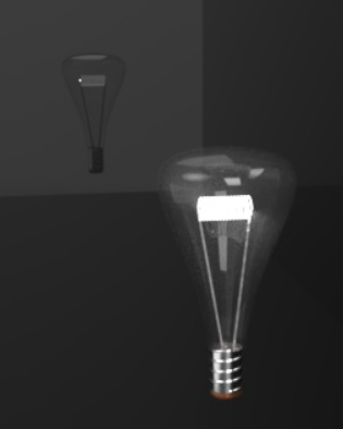
The following are Photometric light options:
Photometric light:
-
Tint - Additional tint color for emitted light (for example, for simulating gels). The default value is white (R: 255; G: 255; B: 255).
-
Color temperature - Color temperature, in Kelvin. The default value is 6500.
-
IES file - The IES light profile used to specify the light distribution. See Add a custom IES light profile for more information.
-
Flip orientation - Reorients the light profiles up vector, which is oriented towards the y direction by default, towards the z direction. The default is enabled.
-
Rotation - Rotates the distribution around the light profiles up vector. The default is disabled.
-
Lumens or multiplier - Light intensity. If Absolute Profile is disabled, then this is the lumen output of the light. If enabled, then this is a multiplier applied to the native light profile intensity. The default value is 2000.
-
Absolute profile - Controls whether the intensity is lumen output of the light (disabled) or multiplies the native light output (enabled). The default is disabled.
-
Intensity is power - If enabled, the intensity is interpreted as power. Consequently, the output is divided by the area of the light source to yield radiance. That means the scene brightness stays about the same if the light source surface area is enlarged. The default is enabled.
-
Front emission only - Disables emission on the backface of an area light. This is required for cylindrical lights to prevent illumination from leaking out the open cylinder caps. Technically, this should also be set for spherical lights, even though these lights will not leak. The default is disabled.
-
Additional emission - Used to add a basic Lambertian emission to the light. Useful for avoiding dark light sources when viewed directly. The default value is 0.
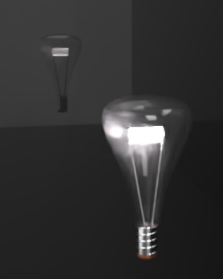
Photometric light example
Lumens or multiplier: 20000; Flip orientation: disabled
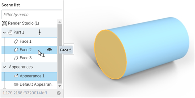
To create a transparency for a part face:
-
Select the part or face in the Scene list or graphics area.
-
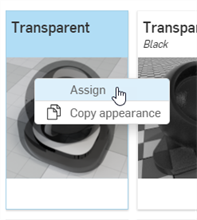
Search the Appearance library for Transparent. Right-click on the transparent thumbnail, and click Assign:
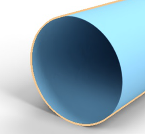
In the example below, the transparency is applied to the cylinder's front face. The face remains. but is now transparent through to the other faces:
A common task is to place a logo or text on a surface or part.
While the approach outlined here is a valid way to add a sticker to a surface or part, Render Studio now automatically imports Decals when a Part Studio that uses Decal features is inserted. This is the recommended approach. See Working with Decals for more information.
-
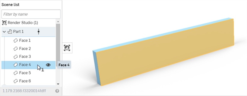
Create a model and bring it into a Render Studio scene.
-
Select the part or face in the Scene list or graphics area:
-
In the Appearances library, search for sticker, then right=click on the Add sticker overlay thumbnail and select Assign from the context menu:
-
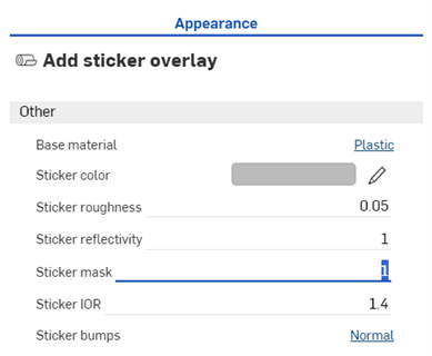
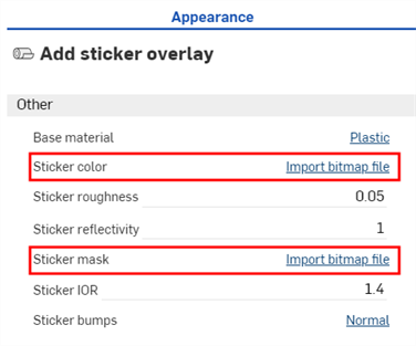
In the Appearance panel, set the Sticker mask to 1:
-
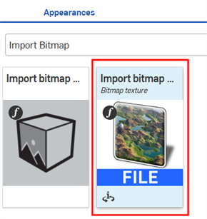
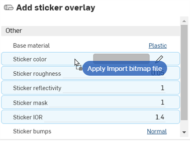
In the Appearances library > Appearance functions folder, Locate the Import bitmap file — Bitmap texture function (first image below), then drag and drop it over the Sticker color parameter in the Appearance panel (second image below). This allows selection of a file to be used for the sticker.
-
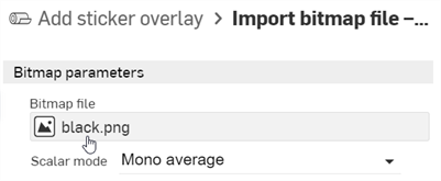
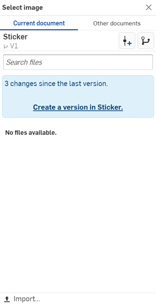
Click on the Bitmap file (black.png) to open the Select image dialog.
-
Do one of the following:
-
Select a bump map file from the Current document
-
Click Other documents to locate a file in another Onshape document
-
Click the Import link at the bottom of the dialog to locate a bump map file (.jpg or .png) from your computer. When selected, click the Open button:
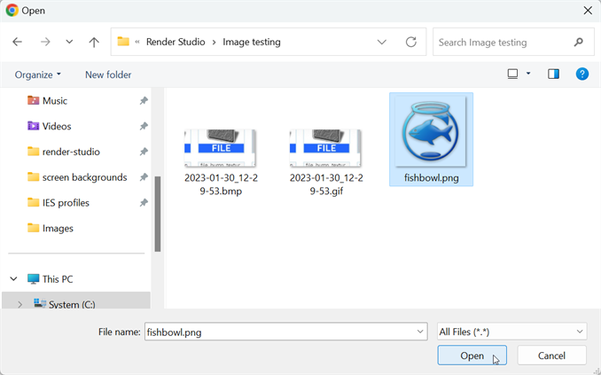
Once the notification indicates the upload is complete, you will not yet see the image in the Select image dialog. This is because the Render Studio scene is a snapshot of the part, Part Studio, or Assembly at the time of import, and this image is brought into the Onshape document post-import. A new version is now required, in order to update the scene. Click the Create a version in [Document name] link in the Select image dialog:
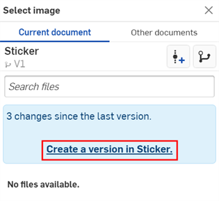
The Create version dialog opens. Enter the version information and click the Create button.
-
-
Once the new version is created, the sticker file is located in the Select image dialog. Click it to select it:
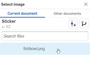
-
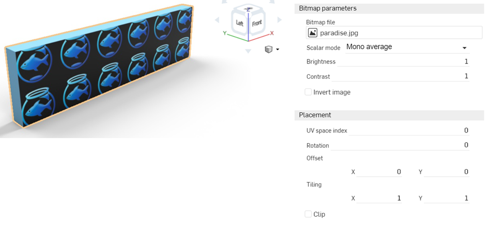
Once selected, the file is loaded into the Bitmap file parameter. Use the Placement options to set up the proper location for the sticker. By default, the Tiling is set to a repeating 1 x by 1 y, and is not offset or rotated:
-
Set Tiling to 6 x by 6 y to increase the image size, and check the Clip option, which forces the sticker not to repeat. Here, the sticker is also offset to show at the far left of the face. Write down these settings, as they are needed later, when applying a mask.

-
At the top of the Appearance panel, click the Add sticker overlay link. This returns the Appearance panel to the parent sticker.

-
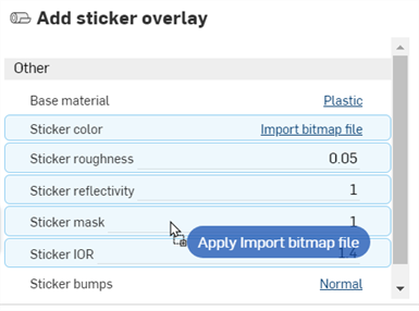
Apply the same bitmap file (and settings) to the mask. Drag the Import bitmap file — Bitmap texture function from the Appearance library > Appearance functions folder, and drop it on the Sticker mask parameter in the Add sticker overlay Appearance in the Appearance panel. In the Placement submenu, enter the exact same settings entered previously for the sticker file: Tiling, Clip, Offset, and Rotation.
-
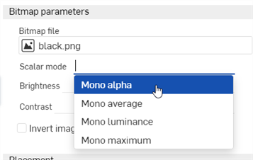
Select Mono alpha in the Scalar mode dropdown in the Bitmap parameters submenu:
-
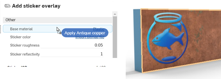
The default Base material parameter is plastic; however, any Appearance can be applied to the face, without affecting the sticker. Locate an Appearance from the Appearance library and drag and drop it on the Base material parameter to add it to the face:
-
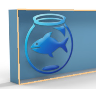
If desired, the face can be made transparent, while keeping the sticker in place, as shown below:
Since even stickers have a small amount of height to them, create a face that is .1 mm in depth above the main face where the sticker is applied when the part is modeled. Then apply the sticker to this face, as outlined below. This creates more realistic sticker edges.
If you don't see the Create version link in the Select image dialog, click the Create version button (![]() ) on the Document panel to open the Create version dialog. Create the new version. Close and reopen the Select image dialog. The imported image should now be available.
) on the Document panel to open the Create version dialog. Create the new version. Close and reopen the Select image dialog. The imported image should now be available.
See Importing files for more information about uploading files.
To alter the sticker and/or mask settings, click the Sticker color or Sticker mask's Import bitmap file link, respectively, then adjust the settings. To keep both sticker and mask in sync, both sets of settings must be updated to match:
See Render Studio Examples and Resources for more information.
