Render Studio Examples and Resources
![]()
Only available for
This topic includes additional examples and resources to get the most out of the Render Studio application.
To add a spot light and reflective surface in an Assembly:
-
Create a part used as a light source in the Assembly. The first image below shows a disk part used as a bulb inside a lamp head. Next, point the lamp head at an object, The second image below shows the lamp pointed at an artist model. Create a surface beneath both objects; a yellow surface table in the example below:
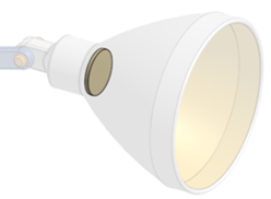
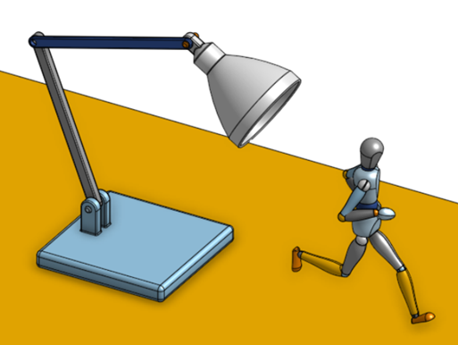
-
Create a Render Studio tab and create a scene from the Assembly.
-
Optionally, click the View tools dropdown (
 )
and select Background. Check Enable background, and then click the Color edit icon (
 ). Select a neutral color from the Select color dialog:
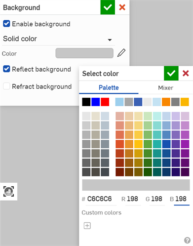
-
Select the bulb part in the Scene list. Filter the Appearance tab for spot light. Right-click on the spot light thumbnail, and select Assign from the context menu:
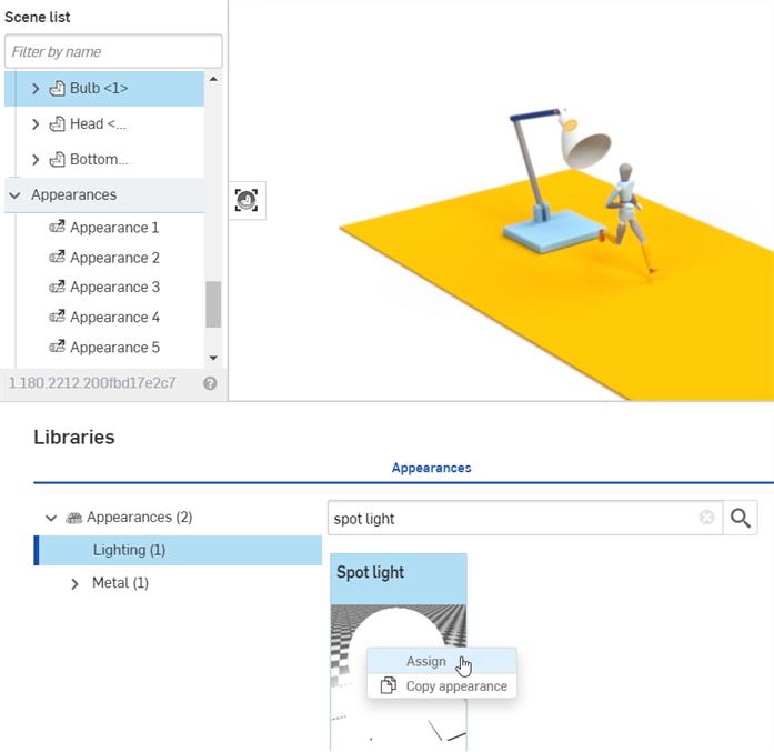
-
Click the Appearance panel icon (
 ) to open the Appearance panel's Spot light parameters. In the Other submenu, change the Flux value to roughly 6000 (first image below). The Flux parameter may require higher or lower values, depending on the size of the scene entities. The light appears on the artist model (second image below):
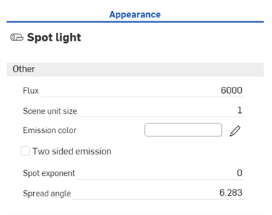
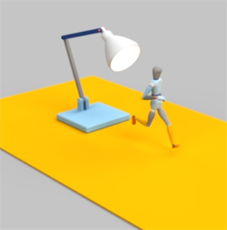
-
Select the table surface in the Scene list (first image below). In the Appearance panel, change the Base color to black (second image below).
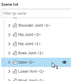
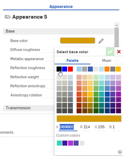
-
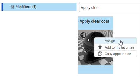
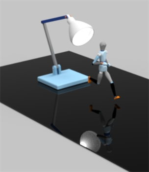
In the Appearances library, locate and assign the Apply clear coat Appearance (first image below). The lamp, light, and artist model are reflected in the clear surface (second image below):
-
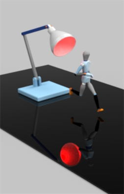
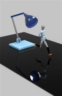
To alter the color of the bulb, alter the bulb's Spot light color in the Appearance panel (first image below), or assign an appearance with a color parameter to the lamp head (second image below). A combination of both is shown in the third image below:
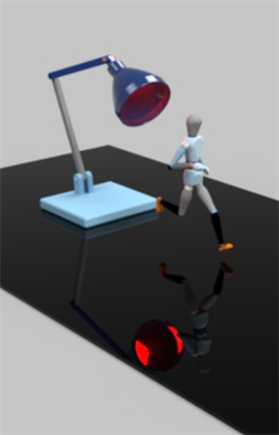
Using this method, the light emanates from all directions of the bulb part (the disk). To emit light from only the front of the disk, zoom into the disk part's front face, then click and drag the spot light appearance and drop it on the disk. When the context menu opens, select Assign to face.
A simple way to change from one metal Appearance material to another is via the color attribute. This example creates a polished metal Appearance and alters the metal's material (steel, brass, copper, and more) by altering its color parameter.
Use this technique on any appearance that has an associated color parameter; metal, or otherwise; for example, wood, stone, ceramic, glass, and cloth, among others.
-
Create the model in Onshape. Then create a scene from the Part Studio or Assembly.
-
Select the part(s) In the Scene list or graphics area.
-
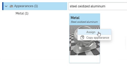
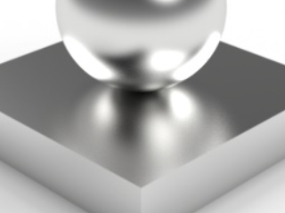
Search for steel oxidized aluminum in the Appearances library. Right-click on the Appearance's thumbnail, and click Assign from the context menu (shown in the first image below). The result is a polished steel appearance (shown in the second image below):
-
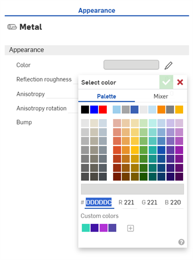
In the Appearance panel, click the Color parameter's edit icon (
 ):
):
-
Select an alternate color from the Select color dialog.
Use the following table as a general guideline to map various metal types to their RGB colors, keeping in mind that every type of metal has a range of colors depending on the age, composition, and other factors of the metal:
Display Name R/G/B color channels Aluminum 230/230/230 Bismuth 208/203/182 Brass 237/216/134 Bronze 165/128/103 Carbon steel 73/73/71 Chrome 253/253/254 Copper 221/151/120 Gold 249/217/153 Cast Iron 195/192/192 Nickel 198/193/180 Pearl 249/248/246 Silver 244/243/240 Stainless steel 198/198/197 Steel 221/221/220 Titanium 191/188/182 Following are some examples that show how color affects the metal type:
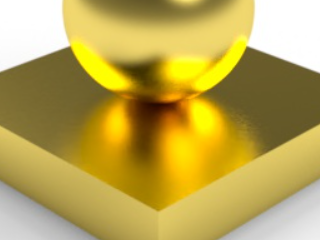
Brass (R: 237; G: 216; B: 134).
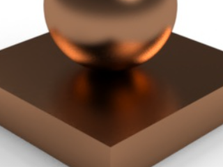
Bronze (R: 165; G: 128; B: 103).
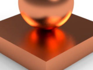
Copper (R: 221; G: 151; B: 120).
-
Non-traditional colors can also be used. For example, use the following R: 149; G: 191; B: 121 color combination to create a metallic emerald:
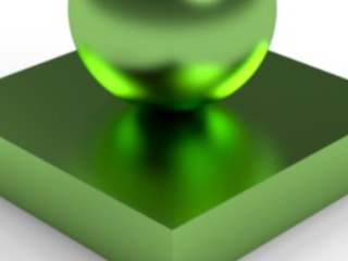
-
(Additional Option) Use the Reflection roughness setting to alter the highlights and blur. Lower values result in brighter highlights and clearer reflections. Higher values result in duller highlights and more blurred reflections. By default, the Reflection Roughness is set to 0.1 (shown in all the previous examples).
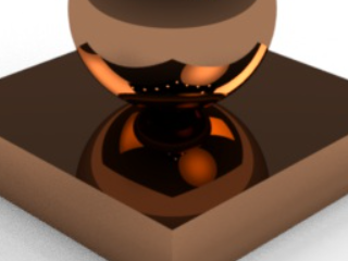
Reflection roughness: 0
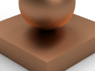
Reflection roughness: 0.25
-
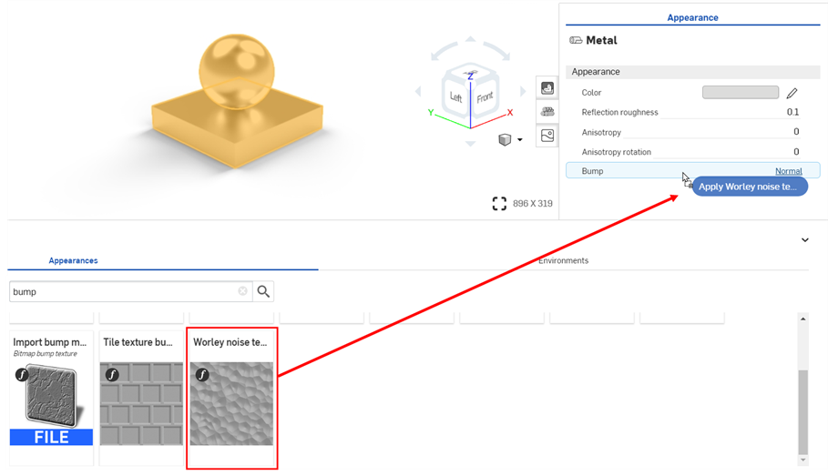
(Additional Option) Add a texture to the Bump option. See Add a bump texture for more information. In the example below, search for Bump in the Appearance functions folder. Drag and drop the Worley noise texture bump map function on the Bump parameter in the Appearance panel:
-
The Worley noise texture bump map parameters automatically open in the Appearance panel. Edit the texture's parameters as required. In the examples below, the Color of the steel was changed to R: 128; G: 128; B: 128 to create a Carbon steel appearance. Additional texture settings are outlined below each example. For reference, the model square is .5 m length x .5 m width x .1 m height. The diameter of the sphere is .3 m.
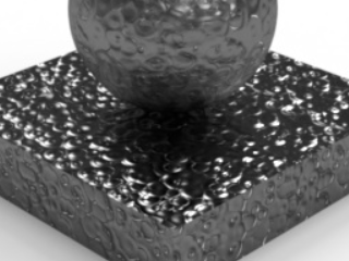
Size: 0.025; Apply_marble: check; Noise_bands: 0.5
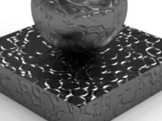
Size: 0.04; Apply_dent: check; Noise_bands: 0.6; Noise_threshold_high: 0.3
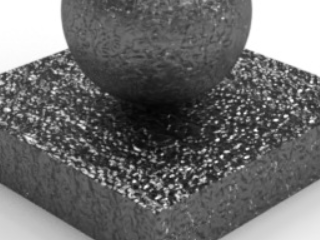
Size: 0.007; Apply_marble: check; Factor: 3; Noise_bands: 10; Noise_threshold_high: 0.1; Noise_threshold_low: 1; Edge: 0.4.
This technique applies a metallic flake coating to an existing Appearance.
-
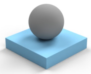
Create the model. Then create a scene from the Part Studio or Assembly. The model here uses two parts: a square .5 m length x .5 m width x .1 m height; and a sphere with a .3 m diameter:
-
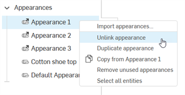
Since both parts have an externally linked Appearance, select each part's Appearance, right-click and select Unlink Appearance. This must be done one Appearance at a time. It ensures the parts have no associated Appearance to start:
-
In the Scene list or graphics area, select one of the parts (Part 2 in the example below):
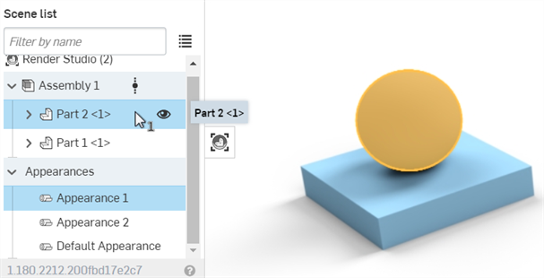
-
In the Appearance library search for Apply clear, Right-click on the Appearance's thumbnail and select Assign from the context menu. The result is a metallic coating applied to the selected part.

-
Deselect the first part (or press the spacebar to clear the selection). In the Scene list, drag and drop the Apply clear coat Appearance on the second part (Part 1 in the example below). This applies the same clear coat Appearance to the other part.
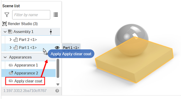
-
Select the Apply clear coat Appearance in the Scene list.
-
Click the Appearance panel icon (
 ) to open the Appearance panel.
 -
In the Appearances library, search for apply flake. Drag and drop the Appearance's thumbnail on the Base parameters > Base material parameter in the Appearance panel:
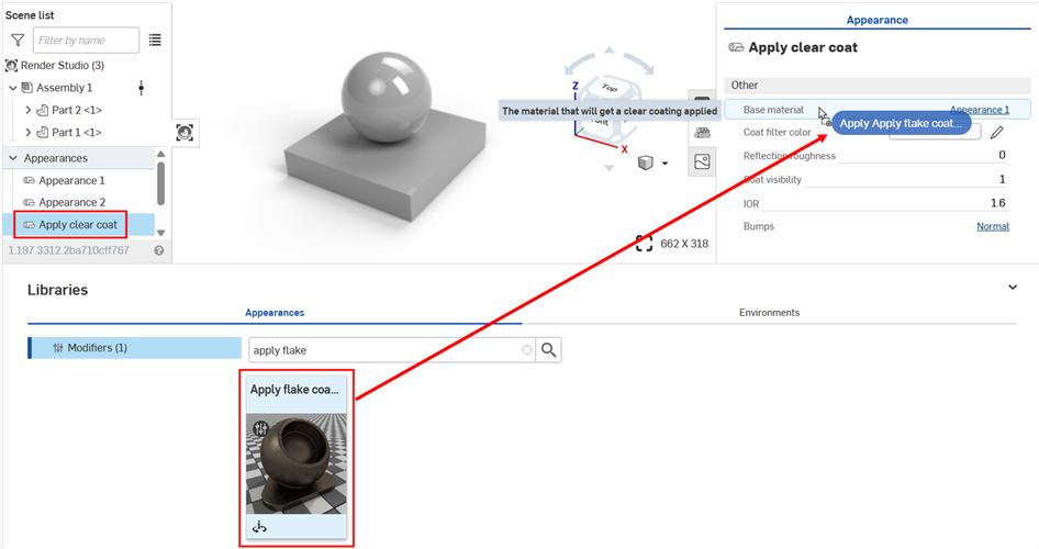
-
Adjust the parameters for the flake coating in the Global submenu as required. Any changes made to the Appearance affects both parts in tandem, since both parts are associated with the same Appearance.
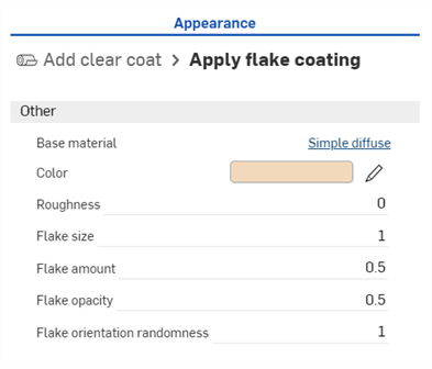
-
Base material - Material on which the flake layer is applied.
-
Color - Flake color.
-
Roughness - Metallic flake roughness.
Flake size - Metallic flake size, in mm.
-
Flake amount - Amount of visible metallic flakes.
-
Flake opacity - Metallic flake visibility.
-
Flake orientation randomness - Larger numbers increase sparkle radius around highlights. Lower numbers decrease or dull the sparkle radius.
Below are some examples. The first example shows the default. The second example shows some alterations to the flake to give the metal a foil appearance. The third example creates a marble appearance, turning metal into stone. Parameter adjustments are noted in the captions below the images:
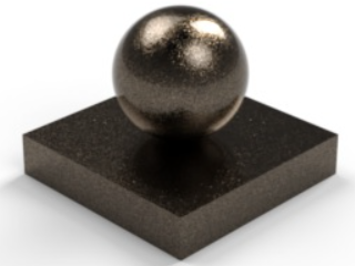
Default settings when applied to a Clearcoat. |
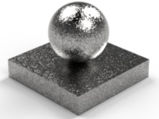
Flake amount: 1.000; Flake orientation randomness: 1.000; Color: R: 223 / G: 222 / B: 220; Flake opacity: 1.000; Roughness: 0; Flake size: 2 |
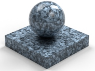
Flake orientation randomness: 0; Color: R: 202 / G: 226 / B: 247; Flake opacity: 1.000; Roughness: 0.5; Flake size: 10 |
Tips
-
Add the Apply flake coating to any material's Base appearance. For example, instead of applying it to the Clear coat Appearance, apply it to the Add sheen Appearance.
-
Many Appearances already have the flake coating parameters built into them; for example, the Metallic paint appearances.
This technique shows how to use the Apply thin metal coating as the start for a powder coated metal Appearance.
-
Create the model in Onshape. Then create a scene from the Part Studio or Assembly. The model here uses two parts: a square .5 m length x .5 m width x .1 m height; and a sphere with a .3 m diameter:

-
Since both parts have an externally linked Appearance, select each part's Appearance, right-click and select Unlink Appearance. This must be done one Appearance at a time. It ensures the parts have no associated Appearance to start:

-
In the Scene list or graphics area, select one of the parts (Part 2 in the example below):

-
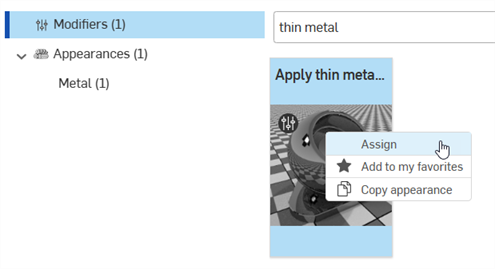
In the Appearance library search for thin metal, Right-click on the Appearance's thumbnail and select Assign from the context menu. The result is a metallic coating applied to the selected part.
-
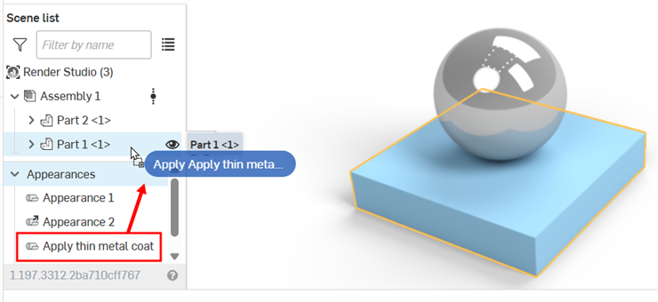
Deselect the first part (or press the spacebar to clear the selection). In the Scene list, drag and drop the Add thin metal coat Appearance on the second part (Part 1 in the example below). This applies the same thin metal coat Appearance to the other part.
-
Select Appearance 1 in the Scene list.
-
Click the Appearance panel icon (
 ) to open the Appearance panel.
 -
Click the Base color parameter's edit icon (
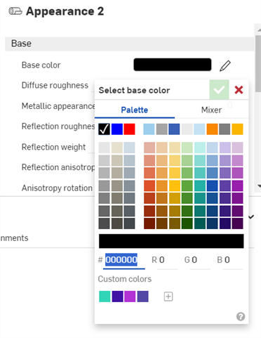
 ) and select Black. You can alter the color as required (see
Change Appearance material type with color).
-
Deselect Appearance 1 and select Appearance 2 in the Scene list. Apply the same black color to its Base color parameter in the Appearance panel.
-
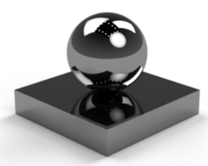
Deselect Appearance 2 and select the Apply thin metal coat Appearance in the Scene list.
-
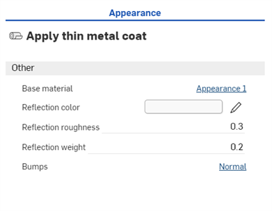
In the Appearance panel > Global submenu, set the Reflection roughness to 0.3 and Reflection weight to 0.2. Any changes made to the Appearance affects both parts in tandem, since both parts are associated with the same Appearance.
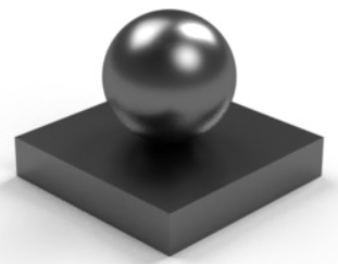
-
Base material - Material on which the metal coat is applied.
-
Reflection color - Metal coat color.
-
Bumps - Normal or bump map applied to the metal coat.
-
Reflection roughness - Metal coat roughness.
-
Reflection weight - Metal coat opacity.
-
-
In the Appearances library, search for Perlin in the Appearance functions folder. Drag and drop the Bump map — Perlin noise texture function thumbnail on the thin metal coat Bumps parameter in the Appearance panel:
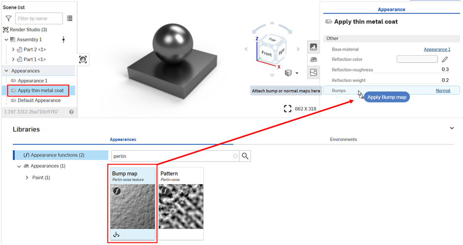
-
The texture is applied and automatically opens in the Appearances panel. This is verified by viewing the hierarchical breadcrumb trail at the top of the Appearance panel:

-
In the Noise parameters submenu, set the Bump strength to 3. In the Placement submenu, set the Tiling to 500 x by 500 y by 500 z. The final result is shown in the second image below:
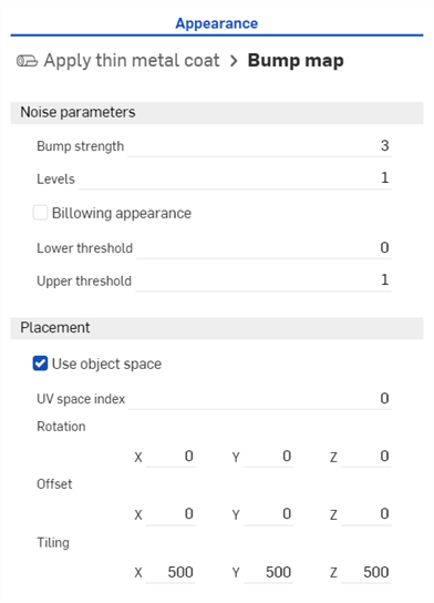
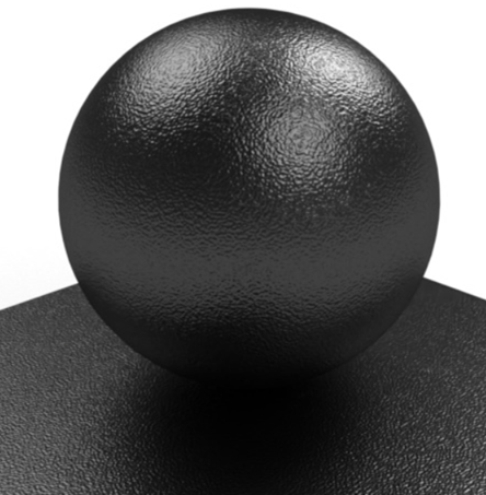
As an alternative to the Bump map — Perlin noise texture, use the Bump map — Flow noise texture, or import a custom texture as a file. See Add a custom bump texture.
The following outlines how to render liquid inside a glass.
-
Create a model of the glass and the liquid.
The following shows a cross section of the two parts: The outer glass and the liquid inside. To create a more realistic render, ensure there is an overlap between the glass and liquid inside the glass. This results in more accurate light transmission and refraction between the two adjacent clear Appearances, glass and water:
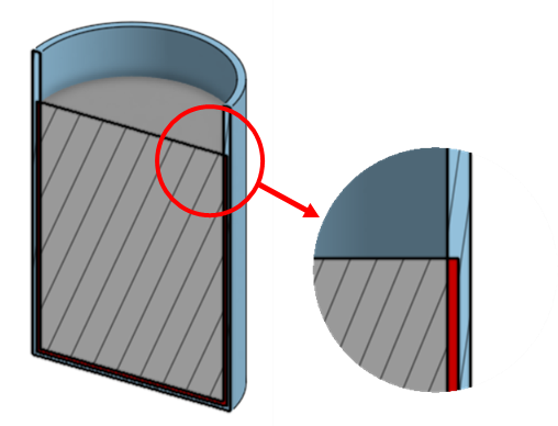
-
Create a scene from the Part Studio or Assembly. In the Scene list, select the glass. In the Appearances library navigate under the Glass folder and look for the Glass— Clear Appearance. Right-click on the Appearance's thumbnail and click Assign from the context menu.
-
In the Scene list, deselect the glass (or press the spacebar), and then select the liquid. In the Appearances library open the Water folder. Right-click on the Pool water — Clear Blue Appearance's thumbnail and click Assign from the context menu.
-
At this point, the liquid has a blue tint applied (shown in the second image below). With the liquid still selected in the Scene list, click the Appearance panel icon (
 ) to open the Appearance panel. Under the Appearance submenu, set Water tint and Water absorption to 0. This produces a glass of colorless water (shown in the third image below).
 -
To remove all waves from the water, set the Wave strength to 0 (also shown in the third image below):
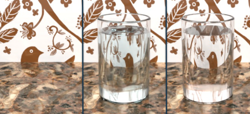
The first image shows the back wall and marble table surface. When the glass and liquid are put in place, the effect of light transmission, reflection, and refraction of the glass and water against those surfaces are seen in the second and third images.
-
The above examples all work with clear liquids, but you can also create a more opaque liquid, such as milk. To do this, select the liquid in the Scene list. Search for wax in the Appearance library. Right click on the Wax — Colored Appearance, and select Assign from the context menu. In the Appearance Panel, set the Color to white, and Distance to somewhere between 0.001 to 0.01:
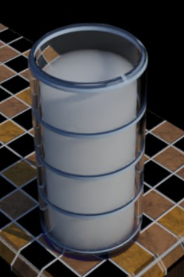
If modeling an object that is fully enclosed within another object; for example, an ice cube part fully submerged in the water part, both parts do not require an overlap. Model them both flush, without an overlap or gap between them.
There are many Clear glass Appearances, and two Glass — Clear Appearances. Either can be used.
See Chapter 15 - Physically plausible scene setup in the NVIDIA Iray - Programmer's Manual for more information.
This technique can be used to create a custom metal grill using the Metal Grill Appearance.
-
Create the model in Onshape. Then create a scene from the Part Studio or Assembly. The example used here is a simple box that is .5 m length x .5 m width x .5m height.
-
Select the part in the Scene list or graphics area.
-
Search grill In the Appearances library. Right-click on the Metal Grill — Circles Appearance's thumbnail and click Assign from the context menu (shown in the first image below). The result is a metal box with circle cutouts (shown in the second image below):
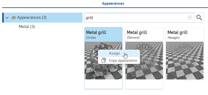
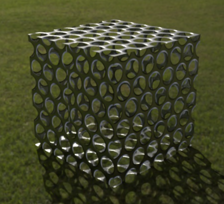
The example in the second image shows the grill with the Green point park Environment applied as a background.
-
In a photo editor (Adobe Photoshop or GIMP is recommended), create two files: a Cutout texture and a Bump map. In this example, a spade cutout was created at 300 x 300 pixels. The Cutout texture is a mask file, which is black and white, with no other colors. The black areas of the image represent the transparent grill pattern. This image is then duplicated, blurred, and a bump map filter is applied. This results in the third image below, used for the Bump file:

The first image (left) is used for the Cutout file. This image is then duplicated and blurred (middle), and then run through a Bump map filter (right). It is this third image above which is used for the Bump file.
-
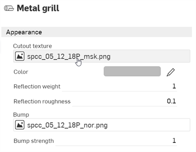
With the part selected, click the Appearance panel icon (
 ) to open the Appearance panel. Click the Cutout texture parameter's file:
-
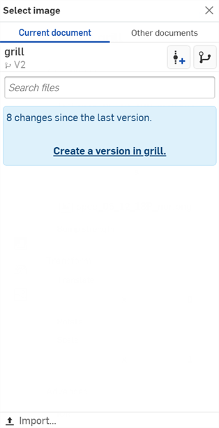
The Select image dialog opens, where you can access the image from a current or other document, or Import an image. In this case, click Import, and select the black and white Cutout texture image from your computer.
-
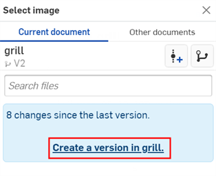
Once the notification indicates the upload is complete, you will not yet see the image in the Select image dialog. This is because the Render Studio scene is a snapshot of the part, Part Studio, or Assembly at the time of import, and this image is brought into the Onshape document post-import. A new version is now required, in order to update the scene. Click the Create a version in [Document name] link in the Select image dialog:
-
The Create version in [Document] dialog opens. Enter the version information and click the Create button:
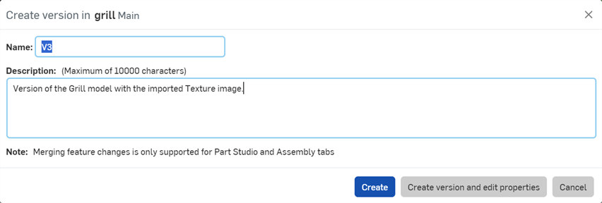
-
The texture image is now located in the Select image dialog. Click it to select it:
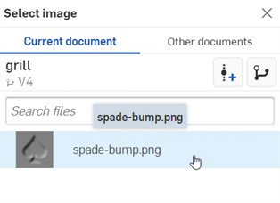
-
The image is now used for the Cutout texture parameter file:

-
In the Appearance submenu, set Reflection weight to 0.7 and Bump strength to 0.2. In the Transform submenu, set Translate to 0.5 x by 0 y and Scale to 0.1 x by 0.1 y (shown in the first image below). The result is a metal box with the custom spade cutouts (shown in the second image below):
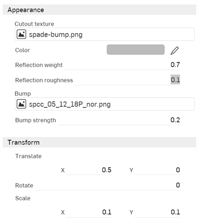
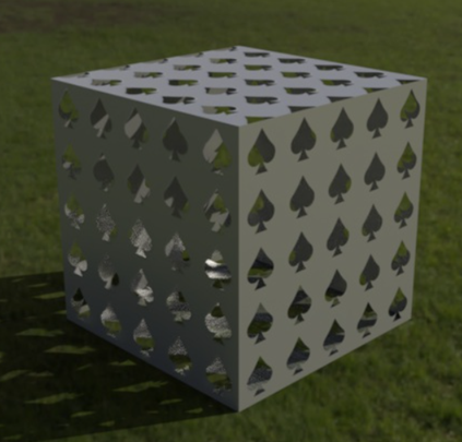
If you don't see the Create version link in the Select image dialog, click the Create version button (![]() ) on the Document panel to open the Create version dialog. Create the new version. Close and reopen the Select image dialog. The imported image should now be available.
) on the Document panel to open the Create version dialog. Create the new version. Close and reopen the Select image dialog. The imported image should now be available.
See Importing files for more information about uploading files.
Tips
-
Adjust the Transform parameters to make the cutouts larger or smaller, move them along the box edges, or even Rotate them from -360 degrees to +360 degrees.
-
To apply the cutouts to only one side of the box, see Add an Appearance to a Scene list entity.
-
For alternate Appearance cutout options, filter the Appearance library for Mesh or apply the Add cutout Appearance. Many of these Appearances use the same techniques outlined here. In the case of some Appearances, the colors in the custom pattern file used for the mask may need to be inverted before they are imported and loaded into the Cutout texture.
Apply a mesh appearance with a custom mesh pattern to create a fence.
-
Model two parts that are parallel to each other: a circular tube and a rectangular box. The circular tube is used for the fence railing, and a face on the box is used for the fence:
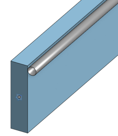
-
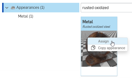
Create a scene with the two parts. In the Scene list, select the railing part. In the Appearances library, search for the Metal — Rusted oxidized steel Appearance. Right-click on the thumbnail and select Assign from the context menu:
-
Click the Appearance panel icon (
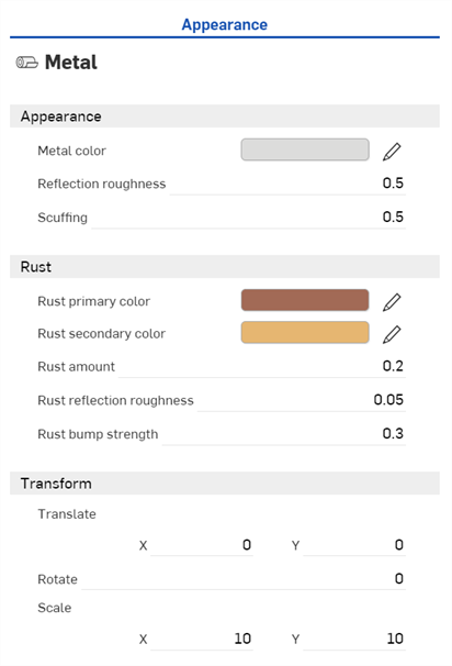
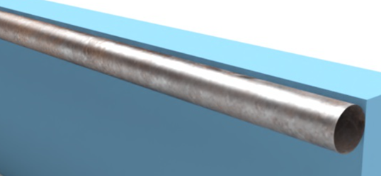
 ) to open the Appearance panel. Alter the settings as required. Here, the following settings were altered from their defaults: Reflection roughness: 0.5; Scuffing: 0.5; Rust amount: 0.2; Rust bump strength: 0.3; Scale: 10 x by 10 y. These settings create a worn metal appearance:
-
Deselect the railing part in the Scene list (or press the spacebar). Click the arrow to the left of the box part to reveal all box part faces (Part 1 in the image below):
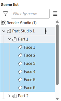
-
Select all sides except the one that is parallel and touching the railing. In the Appearances library, search for Transparent, right-click on its thumbnail and select Assign from the context menu (shown in the first image below). This applies the Appearance to all selected sides (shown in the second image below):
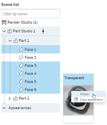
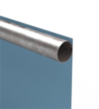
-
In the Scene list, deselect all sides and select only the side that is touching the railing. In the Appearances library, search for the Black base plastic Appearance. Right-click on the thumbnail and select Assign from the context menu:
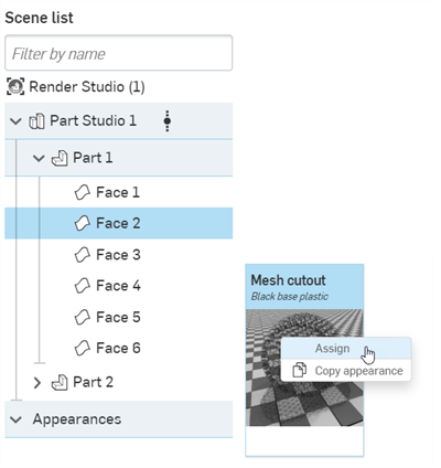
-
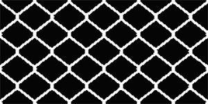
In a photo editor (Adobe Photoshop or GIMP is recommended), create and save a fence pattern file. The pattern should be a high contrast black and white image that is a seamless pattern (it wraps around seamlessly in all directions). White represents the mesh, and black represents the transparency, similar to the image here:
-
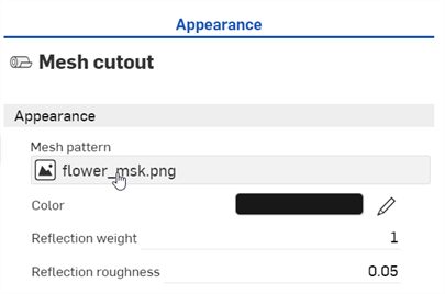
With the Mesh cutiout selected in the Scene list, go to the Appearance panel, and click the Mesh pattern parameter file:
-
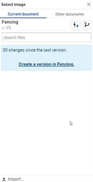
The Select image dialog opens, where you can access the image from a current or other document, or Import an image. In this case, click Import, and select the black and white fence pattern image file from your computer.
-
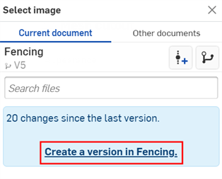
Once the notification indicates the upload is complete, you will not yet see the image in the Select image dialog. This is because the Render Studio scene is a snapshot of the part, Part Studio, or Assembly at the time of import, and this image is brought into the Onshape document post-import. A new version is now required, in order to update the scene. Click the Create a version in [Document name] link in the Select image dialog:
-
The Create version in [Document] dialog opens. Enter the version information and click the Create button:
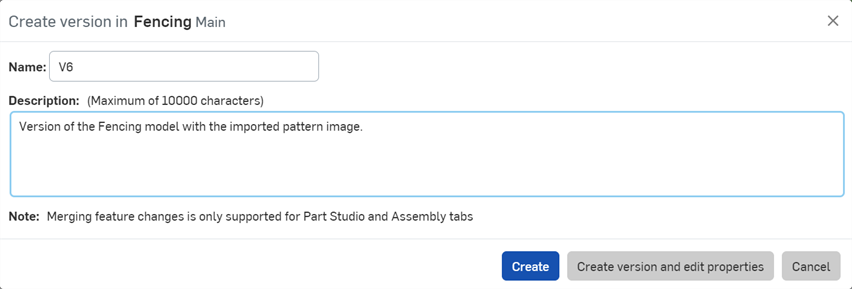
-
The pattern image is now located in the Select image dialog. Click it to select it:
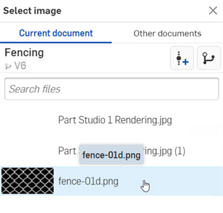
-
Adjust the color and scaling to required specifications, noting that the scaling is dependent on the part dimensions. Higher values create larger fencing (thicker mesh). Smaller values create smaller fencing (thinner mesh). In the image here, the Scale is set to 7 x by 7 y. The Color is adjusted to R: 114; G: 114; B: 114, so it is less black and more silver:
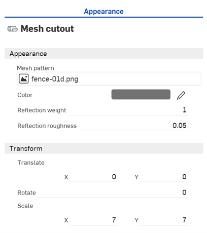
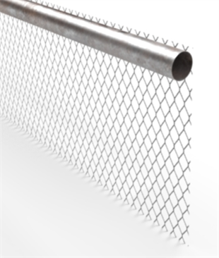
-
Since the railing is slightly too low, in the Scene list deselect the fence (or press the spacebar), select the railing part, click the Transform icon on the toolbar (
 ) and move the Z axis up slightly.
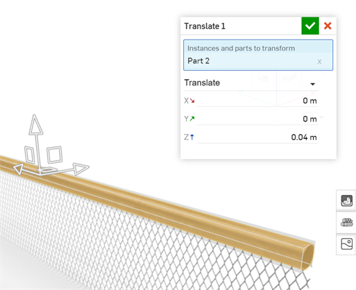
-
In the Environment library, locate and apply an appropriate environment for the fence background (Autumn park in this example):
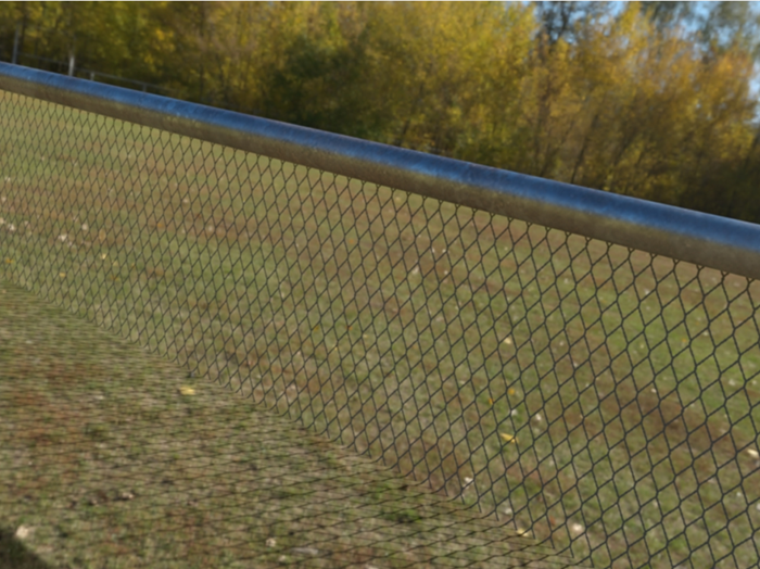
Alternatively, the fence could be modeled as a surface instead of a rectangle. This avoids the process of using the transparency to hide the other rectangle sides. However; depending on how the surface is modeled, Render Studio may see this surface as a 6 sided rectangle, and the pattern may not appear correct.
If you don't see the Create version link in the Select image dialog, click the Create version button (![]() ) on the Document panel to open the Create version dialog. Create the new version. Close and reopen the Select image dialog. The imported image should now be available.
) on the Document panel to open the Create version dialog. Create the new version. Close and reopen the Select image dialog. The imported image should now be available.
See Importing files for more information about uploading files.
This example applies heat treated metal to the model.
-
Create a model to which you want the heat treated metal applied. The following is a model of a valve assembly:
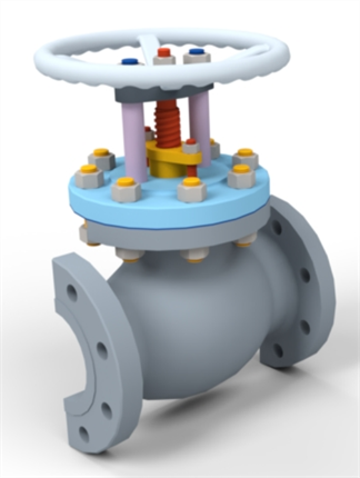
-
Create a scene.
-
Select the part to which you want the steel appearance applied in the Scene list or graphics area. Here, the Valve Body part is selected. Search for Pitted steel in the Appearances library. Right-click on the Pitted steel — Light Appearance's thumbnail and click Assign from the context menu:
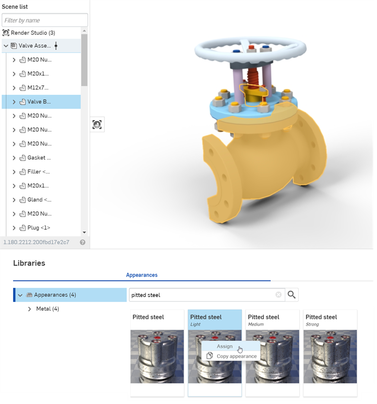
The following shows the Valve Body part with the default Pitted steel - Light appearance:
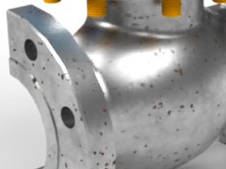
-
To remove the pits in the metal, with the part still selected, click the Appearance panel icon (
 ) to open the Appearance panel. Set the Scale to 0.05 x by 0.05 y, and Rotate to 20:
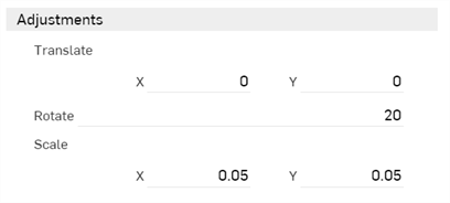
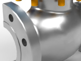
-
Next, the heat treatment options are applied. In the Appearance submenu, set the Heat treatment amount to 2, Rust pits brightness to 1, and the Steel bump strength to 1:
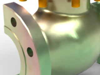
-
In the Appearance submenu, decrease or increase the Steel roughness setting to adjust the amount of metallic shine to specifications:
Adjustments may not always yield the same results shown in the sample images here, especially with Transform options, which will depend largely on model size. The size of the Valve Body part here is approximately 350 mm length by 125 mm width by 250 mm height.
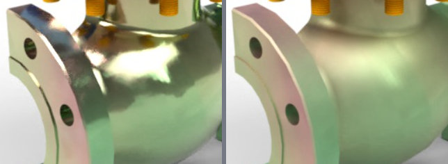
Two different Steel roughness settings; -0.5 on the left, and 0.75 on the right.
This example applies a FFF (Fused Filament Fabrication) appearance to your Part Studio or Assembly. This appearance can simulate the look of a 3D thermoplastic print.
-
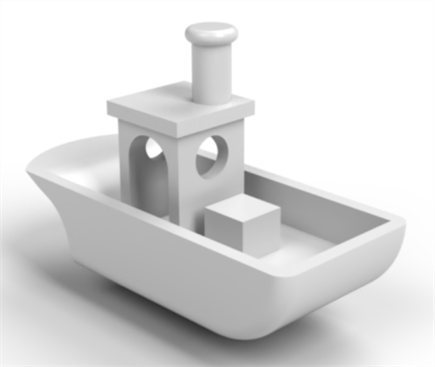
Create a model to which you want the appearance applied. The following is a simple model of a boat:
-
Create a scene.
-
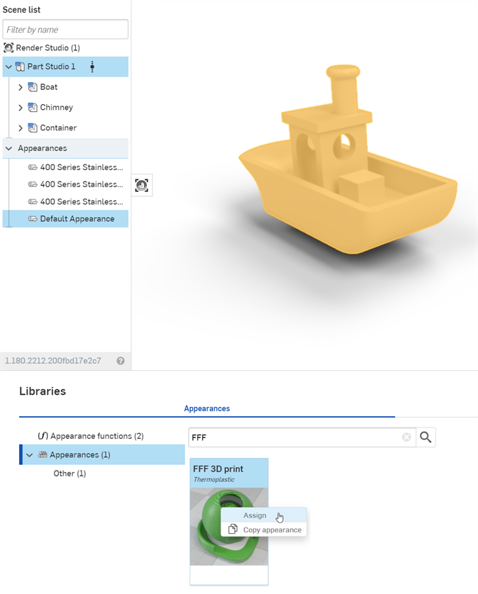
Select the part to which you want the FFF 3D print thermoplastic Appearance applied in the Scene list or graphics area. Here, the entire Part Studio is selected. Search for FFF in the Appearance library. Right-click on the FFF 3D print — Thermoplastic Appearance's thumbnail and click Assign from the context menu:
-
Click the Appearance panel icon (
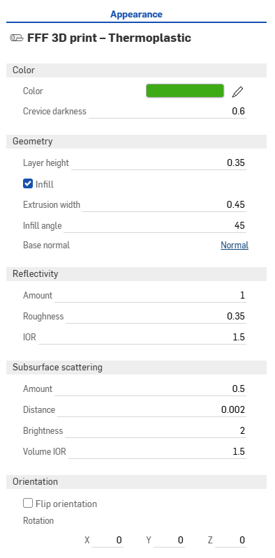
 ) to open the Appearance panel. Make any parameter adjustments as required:
-
Color
-
Color - Thermoplastic color
-
Crevace darkness - Sets the crevice darkness between layer lines. A higher value equals darker crevices.
-
-
Geometry
-
Layer height - Printed layer height (mm).
-
Infill - Creates a rectilinear infill pattern on flat horizontal surfaces.
-
Extrusion width - Top and bottom layer printed extrusion width (mm).
-
Infill angle - Top and bottom layer infill extrusion line angle (in degrees).
-
Base normal - Base normal for the bump map.
-
-
Reflectivity
-
Amount - Surface reflectivity. A higher value equals more reflectivity.
-
Roughness - Surface roughness. A higher value equals broader highlights and blurrier reflections.
-
IOR - Index of refraction (IOR). Controls the reflection's fresnel factor.
-
-
Subsurface scattering
-
Amount - Amount of subsurface scattering seen through the surface. A higher value equals more scattering.
-
Distance - Subsurface scattering distance at which thicker parts appear darker and thinner parts lighter.
-
Brightness - Subsurface scattering brightness. A higher value equals a lighter subsurface scattering.
-
Volume IOR - Thermoplastic volume index of refraction (IOR).
-
-
Orientation
-
Flip orientation - Switch layer line direction from the Z to Y axis.
-
Rotation - Modify the orientation of the layer lines by rotating the degrees of X, Y, and Z.
-
-
The following shows 2 different angles with different lighting intensities, when zooming into the boat detail:
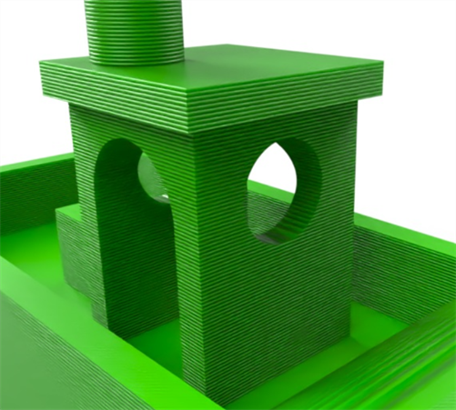
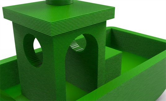
Adjustments may not always yield the same results shown in the sample images here, especially with Transform options, which will depend largely on model size. The size of the boat part here is approximately 12.5 in length by 6 in width by 9 in height.
FFF 3D print functions
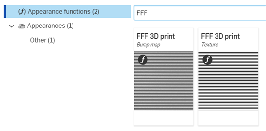
Two functions are also available in the Appearances library > Appearance functions folder:
-
FFF 3D print bump map - Apply the FFF 3D print bump map function to any the Normal parameter of any appearance that accepts bump maps. For example, it can be applied to the Flexible material model appearance's Normal parameter.
-
FFF 3D print texture - Apply the the FFF 3D print texture function to any color parameter of an appearance. This creates patterns of alternating light and dark based on the inputs to simulate layer lines.
Tips
-
The Denoiser can smear the layer line effect introduced by the Appearance/functions early in the rendering process. Disabling the Denoiser is recommended. If it is not disabled, rendering times may be longer. To disable the Denoiser, click the Scene panel icon (
 ) to open the Scene panel, and uncheck Denoiser.
 -
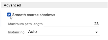
Since the bump map used in the FFF 3D print — Thermoplastic Appearance can produce normals which are dramatically different from the underlying geometry, shading artifacts may be introduced on some geometries. In those cases, click the Scene panel icon (
 ) to open the Scene panel, and check Smooth coarse shadows:
This example applies the OpenVDB volume appearance to apply volumetric effects, simulating real-world elements such as smoke and water.
-
Create a model to which you want the appearance applied. Typically, when modeling volumes, a cube that encompasses the entire element's volume is modeled in a Part Studio, and then brought into the Scene.
-
Create a scene and insert the cube and any other modeled elements from the Part Studios and/or Assemblies.
-
Select the part to which you want the appearance applied in the Scene list or graphics area.
-
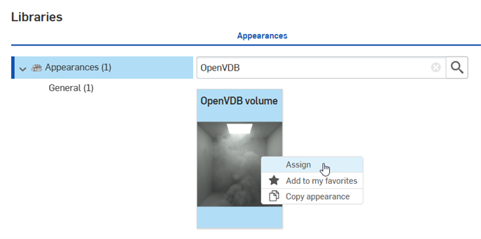
Search for OpenVDB in the Appearance library. Right-click on the OpenVDB volume thumbnail and click Assign from the context menu:
-
Click the Appearance panel icon (
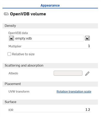
 ) to open the Appearance panel. Make any parameter adjustments as required:
-
Density
-
OpenVDB data - By default this is an empty vdb. Click to open the Select Volume Data dialog, where you can select VDB file describing the density of the volume from the Current document or Other documents.
-
Multiplier - Scales the volume density. Default is 1.
-
Relative to size - If enabled, the volume density changes with scale.
-
Channel - When an OpenVDB data file is selected, the Channel parameter is displayed. Channel is used to display the volume. In most cases this should be set to density.
-
Bounds - When an OpenVDB data file is selected, the Channel parameter is displayed. These are the non-editable OpenVDB data file boundary ranges of the volume's X, Y, and Z axes. This helps indicate the volume's size.
-
-
Scattering and absorption
-
Albedo - Amount of scattering opposed to absorption in [0,1]. Click the edit icon (
 ) and select a color that is applied to the volume.
-
-
Placement
-
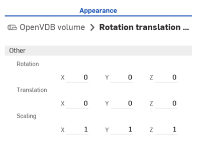
UVW transform - Transforms the volume by the given matrix after clipping. Click the Rotation translation scale link to open the Matrix and adjust Rotation, Translation, and Scaling.
-
-
Surface
-
IOR - Index of refraction for the surface if used in a mesh rather than a volume. Default is 1.2. In most cases, this should be set to 1.
-
-
The results are displayed in the graphics area. In the following example, a 250 x 250 x 250 in. cube was modeled in a Part Studio and inserted into a Render Studio scene. The smoke2.vbd file was selected for the OpenVDB data file:
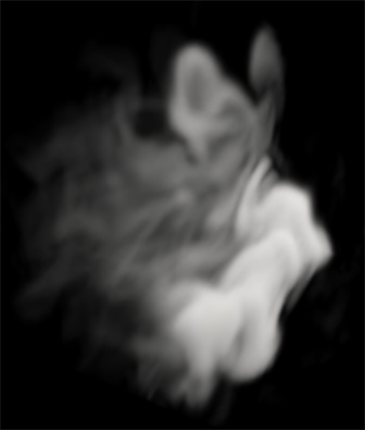
Smoke example. Multiplier: 20; Surface IOR: 1; Rotation translation scale - Rotation: X=0, Y=0.25, Z=0.25; Translation: X=1.5, Y=4, Z=1.25; Scaling: X=1.25, Y=0.6; Z=0.5
Creating a panoramic output file requires Render Studio Advanced. To check if you have this advanced upgrade, open a Render Studio tab. If you see the Upgrade Render Studio button at the top right along the toolbar, you first need to upgrade. Once upgraded, you can continue to create the panoramic output outlined below.
-
In a Part Studio build the geometry representing the environment's significant light sources, using 1 composite part per light temperature.
-
Create a version of the document.
-
Create a new Render Studio scene and insert the contents of the Part Studio.
-
Search for Light in the Appearances library, or navigate to the Lighting folder. Assign light-based appearances to the surface or solid faces (modeled light sources).

-
By default, Appearances may be too dark. Adjust the Lumens or Intensity value, and Color temperature as required. See Light emission for more information on how to use and adjust light Appearances in Render Studio.
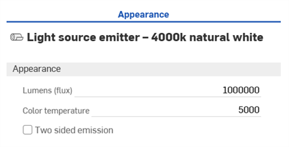
-
In the Environment panel, set the Lighting intensity to 0. This disables any lighting from the environment, and ensures your light sources are derived from only the selected geometry .
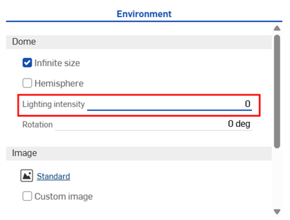
-
Go to View tools > Position and rotation. Set the Rotation X value to 90 degrees, and the Position Z value to the camera's expected tripod height. Ensure all other Position and Rotation values are 0.
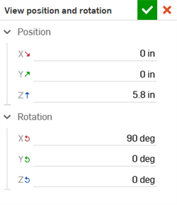
-
Go to View tools > Background, and check Enable background. Ensure black is selected as a Solid color.
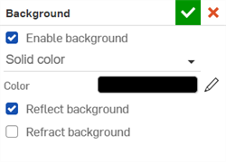
-
Click the Render scene button on the toolbar, and enter the following options:
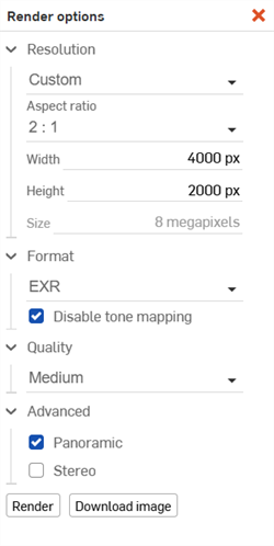
-
Resolution: Custom
-
Aspect ratio: 2:1
-
Height: 2000 px (or larger, if required)
-
Format: EXR or HDR
-
Disable tone mapping: Check this option to enable it. If this is disabled, output is still generated, but it will lack dynamic range since it has been compressed out. As a result, highlights will not be as strong as they should be, and a lot of work is required to adjust the lighting intensity downstream.
-
Advanced: Check Panoramic.
Your scene should look similar to the example below, with the characteristic spherical mapping:
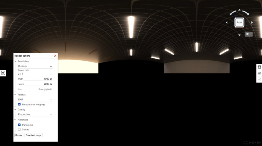
-
-
Click Render.
-
Create and import a geometric model from a Part Studio into a Render Studio scene. Ensure the part’s bottom center is at the Part Studio's origin:
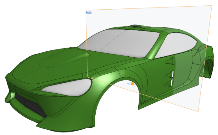
-
Import a backplate image for use as the background in your final render.
-
Create a version of the document.
-
Create a new Render Studio scene and insert the contents of the Part Studio.
-
Assign any Appearances to the parts and faces, as you normally would. See Adding an Appearance to a Scene list entity for more information.
-
Go to the Environment panel. Under the Image settings, check Custom image and select the EXR or HDR panoramic file that was created earlier.
-
The scene is now lit with the panoramic file. If it is too dark adjust the Lighting intensity to a value close to 1, or adjust the Tone mapping (under View tools). Also, optionally set the Rotation to a value between 0 and 360 (negative values are not accepted).
Since the panoramic file is only used for lighting, the Infinite size and Hemisphere options are not required.
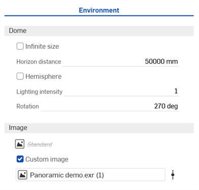
-
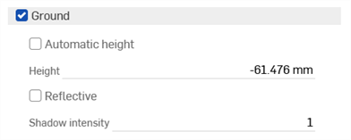
Check Ground. This is used for shadows later.
-
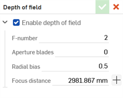
Go to View tools > Depth of field. Check Enable depth of field. This helps create realism.
-
Go to View tools > Position and rotation. Set the Rotation X and Y values to 0/90 or 0/-90, respectively. Set the Position Z value to any value you require. This is the camera's expected tripod height.
-
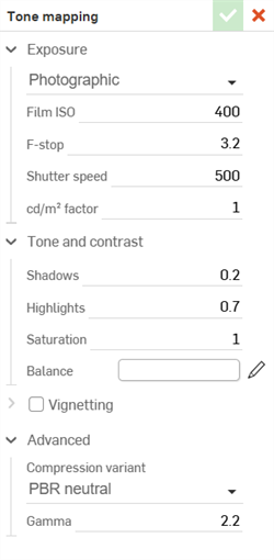
Go to View tools > Tone mapping and enter values as required. This is a matter of personal preferences.
-
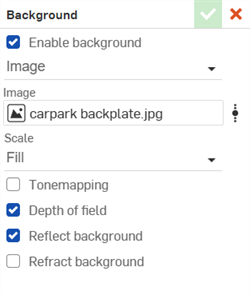
Go to View tools > Background and check Enable background. Select Image, then locate and select the backplate image to import.
-
Check Depth of field and Reflect background. If using a PNG or JPG backplate image, do not enable Tone mapping.
-
It is vital the Focal length setting in Render Studio matches the backplate image. If the focal length does not match, the perspective is incorrect. To match the correct focal length of the backplate image:
-
Check the metadata information for the backplate image.
-
For Microsoft Windows, right-click on the image and select Properties > Details tab.
-
For Apple Mac, right-click on the image and select Get info.
-
-
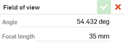
Locate the Camera model and focal length and enter it into the View tools > Field of view > Focal length setting:
-
If it is a Pro level camera like Canon EOS 1DX or EOS 1Ds or Nikon D1, it is a full frame camera. The focal length of the lens should be entered as is.
-
In the case of a pro consumer camera like Canon EOS 70D, it is a cropped frame camera and there is a known crop factor (usually 1.5). Multiply the reported focal length of the lens as reported by the crop factor and enter this value.
-
If there is no backplate image focal length metadata, you must experiment when entering values. You also have the option to download an alternate backplate image, or an image of your own.
-
-
-
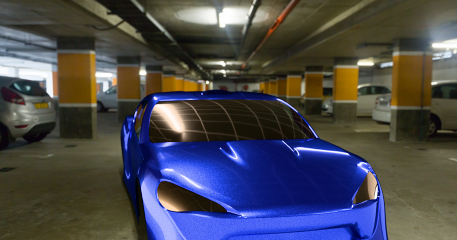
Click the Render scene button and create a final render to PNG or JPG image format:
Building the light emission geometry centered around the origin makes it easier to position the camera correctly in later steps.
Be careful if mixing light temperatures, as wide color ranges can cause issues and may not create the desired results.
The high Lumen (flux) values used in this example are not necessarily physically accurate. This may or may not be an issue depending on the accuracy required. Lumen (flux) is the total output of light over its area, so a larger light has less flux per unit area. If the lights are truly large, they may have a high flux value, though this is not likely the case.
Tone mapping values may also be required.
If you made an EXR/HDR based on full size measurements, ensure the part you are rendering is also full scale. This keeps them both at the same scale.
If the orientation does not appear correct, everything can be transformed in Render Studio later.
Temporarily disable the background (View tools > Background > Enable background). This assists in determining the correct orientation.
Tips
-
If you model surfaces used for light emissions, you may find that the emitted light is not on the correct side. You can either use 2-sided lights or instead model solids and select the solid's faces to use for light emission.
-
Create closed composite parts for grouped/common light sources to make selection easier in Render Studio.
-
It is recommended to create composite parts that group common objects together, especially if they have the same applied Appearance.
-
It is not recommended to create an output that is smaller than 2000 px in height, as that can result in lower quality, where the lights become rough.
-
For realistic rendering, understand that imperfections are real (smudges, fingerprints, roughness, etc.). There are many Appearances in the Appearances library that offer these options.
-
If using PNG or JPG backplate images, do not use Tone mapping.
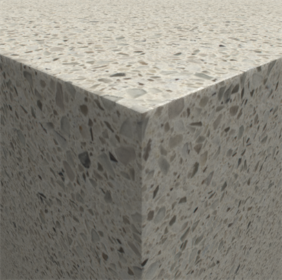
X-rite AxF appearances are a self-contained file format which are output by X-rite scanning devices such as the TAC-7, MA-T12 and MetaVue VS3200. Unlike a texture file these files completely describe an appearances properties and may include both uniform and spatially varying information. Here is an example:
AxF Appearances are popular in various industries, particularly automotive and general product design.
Everything is packaged within an .axf file which can already be loaded in Render Studio.
-
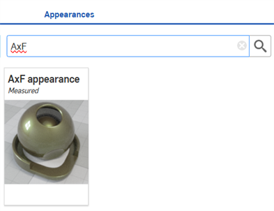
Search for AxF in the Appearances library's General folder:
-
Select the part(s) to which you want the AxF appearance applied.
-
Right-click on the AxF appearance in the Appearances library and select Assign:
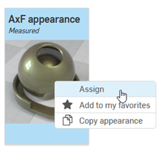
-
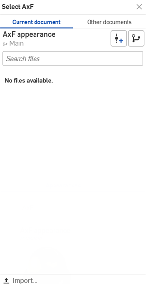
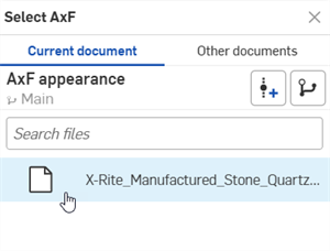
The Select AxF dialog opens (first image). Click Import and locate the AxF file on your local drive. Once this is imported, it can be selected from the dialog (second image below):
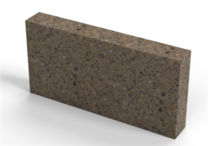
The AxF appearance is applied to the selected part:
-
Once an AxF appearance has been selected, the Appearance panel updates with a set of parameters relevant to the selected AxF appearance type. Click the Appearance panel icon to access the parameters.
Currently there are only 3 such types: svbrdf, carpaint, and volumetric. The parameters that populate the appearance panel for the svbrdf (first image below) and carpaint (second image below) are shown. The volumetric type has no additional parameters.
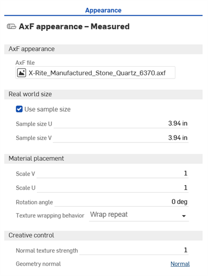
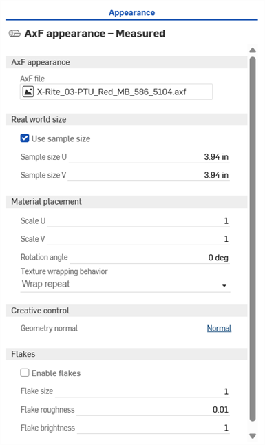
-
Edit the parameters as required:
-
AxF appearance
-
AxF file - File used for the AxF appearance.
-
-
Real world size
-
Use sample size - Enable if the real world measurements of the measured sample are known.
-
Sample size U - The size of the measured sample in meters, measured in the U direction.
-
Sample size V - The size of the measured sample in meters, measured in the V direction.
-
-
Material placement
-
Scale U - Scale factor in the U direction.
-
Scale V - Scale factor in the V direction.
-
Rotation angle - Changes the orientation of the textures on the object.
-
Texture wrapping behavior - Controls the wrapping behavior of the texutre if it fits multiple times on an object. Options are Wrap clamp, Wrap repeat (default), Wrap mirrored repeat, or Wrap clip.
-
-
Creative control
-
Normal texture strength - Can be used to edit the bumpiness of the appearance. At 1.0 it matches the measured bumpiness.
-
Geometry normal - Allows the use of an additional bump mapping effect.
-
-
Flakes
-
Enable flakes - Enables the additional Flakes parameter.
-
Flake size - Artistic control to modify flake size.
-
Flake roughness - Artistic flake reflection roughness control.
-
Flake brightness - Artistic flake brightness control.
-
-
-
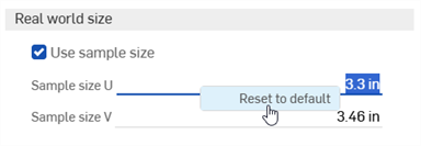
To reset any parameter after it has been set, right-click over the parameter in question and select Reset to default:
Creating a volume adds a cubic region in which the volumetric portion of an appearance exists and is rendered. The volume can optionally be an OpenVDB 3D texture.
Non-advanced users can open a scene that contains Volumes, but their properties are non-editable.
Here is an example output using a Volume to display smoke and fire:
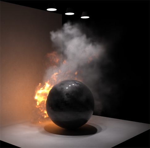
To create and edit a volume:
-
Click the Volume button on the toolbar:

-
The Volume dialog opens. Select from the following options, as required (not all options are available for all Volume types):
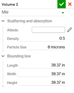
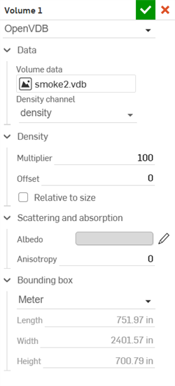
Example of the Mie volume type (left) and OpenVDB volume type (right)
-
Volume type - Select from the following 3 Volume types: Mie, Anistotropic, and OpenVDB.
-
Data
-
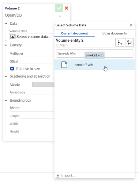
Volume data - OpenVDB volume data. Click this field to open the Select Volume data dialog, where you can locate the OpenVDB data from the Current document or Other documents. Click the Import button at the bottom of the dialog to locate and open the OpenVDB data from your device. Once imported, it can be selected and used in the Render Studio for the volume:
-
Density channel - Data in the volume channel that controls the opacity. Lower values result in a thinner transparent volume. Higher values result in a thicker opaque volume.
-
-
Density
-
Multiplier - Scales the volume density.
-
Offset - Add or subtract density from the entire volume.
-
Relative to size - When enabled, the volume density scales with the physical size of the volume.
-
-
Scattering and absorption
-
Albedo - The color of light scattered by the volume. Click the Select albedo icon (
 ) to open the Select albedo color picker dialog. Select a color for the albedo, and then click the checkmark icon (
 ).
). -
Density - Controls the opacity of the volume. Lower values result in a thinner transparent volume. Higher values result in a thicker opaque volume.
-
Particle size - Average diameter of the particles in the volume.
-
Anisotropy - Influence of light direction on scattering. Values range from -1 specifying backward scattering, 0 specifying isotropic scattering, and 1 specifying forward scattering.
-
-
Bounding box
-
Measurement - Select from Centimeter, Foot, Inch, Meter (default), Millimeter, Yard, or Custom.
-
Scale - If Custom is selected for the Measurement, this uniformly scales the physical size of the volume's bounding box in all directions.
-
-
Length - Bounding box length.
-
Width - Bounding box width.
-
Height - Bounding box height.
-
-
-
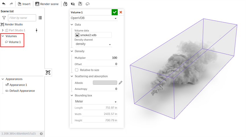
As you edit, the bounding box is displayed in the graphics area, surrounding the volume with a purple outline. The Volume is also added to the Scene list on the left under a Volumes dropdown list:
-
When finished editing, click the checkmark (
 ) to apply the volume. The bounding box disappears and the volume remains in the graphics area:
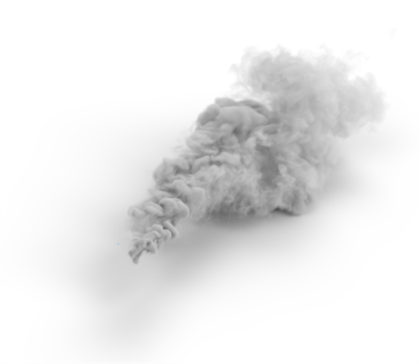
-
To edit the volume at any point after it is applied, double-click the volume in the Scene list to open its dialog.
Further information and resources can be found here:
-
NVIDIA Iray - Programmer's Manual - https://doc.realityserver.com/doc/resources/general/iray/manual/index.html#preface#.
-
NVIDIA Ray Tracing Documentation - https://raytracing-docs.nvidia.com/.
-
Material Definition Language (MDL) handbook - http://mdlhandbook.com/.
-
Additional free environments - https://polyhaven.com/hdris.
-
Additional free textures - https://polyhaven.com/textures.
-
Additional free IES light profiles - https://ieslibrary.com/en/home.
-
Additional OpenVDB volume downloads - https://www.openvdb.org/download/.