Render Studio Interface - Appearances Library

Only available for
Available in: Render Studio
Located at the bottom of the page, the Appearances library contains all the standard attribute combinations that are applied to parts, part faces, or surfaces, to provide a material texture, as well as functions that are applied to appearance parameters:
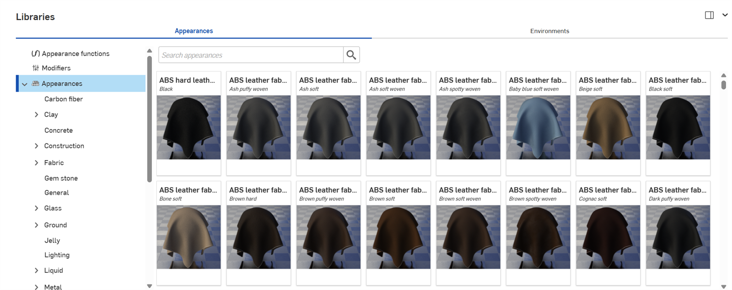
 Navigating the Appearances library
The following sections explain how to navigate the Appearances library interface.
Search
Use the Search appearances field to narrow the appearance results in the library. The Search appearances field only locates appearances within the selected folder. For example, in the image above, if the Ceramic folder is selected, typing a keyword into the Search appearances field and pressing the Enter key shows only results within the Ceramic folder.
Use "and", "+", and "or" operators between words to further refine the search.
Once narrowed by the search, results appear as a thumbnail list on the right side of the Appearances panel. To clear the search, delete the keyword(s) in the Search appearances field and press the Enter key or press the clear field icon ( ).
).
Switching between the horizontal and vertical library views
Click the Show library in the right panel icon at the top right corner of the panel to show the library in the right panel:
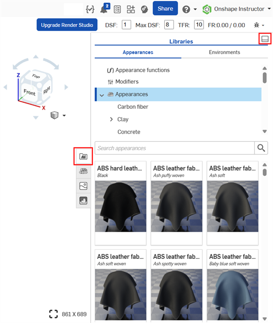
Click on the library panel icon ( ) to close the panel. Click it again to open it.
To place the library back in its default horizontal position, click the Show library in the bottom panel button located at the top right corner of the panel (highlighted in red in the above image).
To apply an Appearance function to an Appearance parameter while the Appearances library is in the right panel, drag the Appearance function on top of the Appearance panel icon and hold until it opens. Then drop the Appearance function on the parameter in the panel. See Using appearance functions for more information.
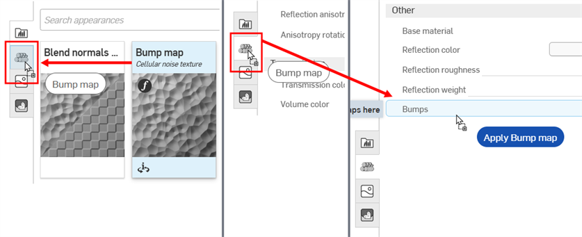
Dragging the Bump map Appearance function over the Appearance panel icon (left). The Appearance panel opens (middle). While still holding, drag the Bump map Appearance function on top of the Bumps parameter in the Appearance panel (right).
Hide/Show library
To hide/show the Libraries panel, click the expand/collapse toggle ( ) at the top right corner of the panel.
View Appearance name
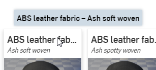
If the entire name of the Appearance is not visible, hover over the name and a tooltip reveals the complete name:
View Appearance description
Click the View description toggle ( ) at the bottom of the Appearance card (top left image below) to flip it and reveal a short description of the Appearance on the back of the card (top right image below). If the description is too long for the card container, hover your cursor over the text for a moment and the card expands to reveal the full description (bottom image below). Click the View description toggle again to flip the card to the thumbnail on the card front.
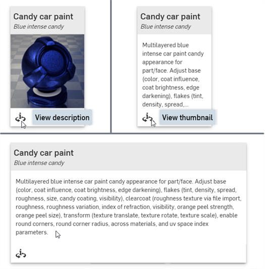
Only one Appearance card can be flipped to the back description at a time. Clicking a second Appearance's View description toggle simultaneously flips the first Appearance's description view to the front (thumbnail) and flips the second Appearance's view to the back (description).
See Render Studio Libraries for a complete list of all appearances and appearance functions.
See Appearance panel for an explanation of the default Appearance parameters.
Notes
-
If an appearance cannot be assigned to a part (the context menu options are not available or do not display when using drag and drop to apply an appearance to a part), it probably means the appearance is a function. Functions must be applied to appearance parameters in the Appearance panel (via drag and drop). See Using Appearance functions for more information.
-
Once an Appearance is applied to a part, Part Studio, or Assembly, check the Appearance panel and browse through the appearance's submenus. This panel contains all editable parameter options for the current Appearance.
-
If the Appearance panel is empty, most likely there are multiple items selected in the Scene list or graphics area. Deselect all but one item, and the Appearance panel should populate with applicable parameters.
-
If the appearance is a light source (Add emission, Diffuse light, Photometric light, Spot light), ensure some walls or other parts are modeled so the light has something tangible against which to reflect. If the light is black, increase the Intensity and/or Unit scale parameter in the Appearance panel. See Light emission for more information.
-
If the appearance contains a pattern or texture that does not appear on the part, it might be too small or too large. In the Appearance panel, increase or decrease the Scale parameter. In addition, try increasing the Intensity parameter, if it exists.
-
To adjust the Appearances/Environments Libraries panel height, hover the cursor over a panel edge. When the cursor turns into a double-sided arrow, click and drag to resize the panel.
-
Known limitation with the OpenVDB Volume appearance - Volume data depends on the geometry to which it is applied. If the volume data is not visible in the graphics area, rotate the geometry slightly in 2 axes in the Part Studio or Assembly, and update the Render Studio. It should now be visible. Alternatively, create a Volume.
Appearances library context menu
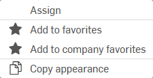
Right-click on an appearance thumbnail in the Appearance library to display a context menu with the following options:
-
Assign - Assign the Appearance to the part(s) and clear any attribute lower down in the Scene list.
-
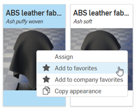
Add to favorites - Add the selected Appearance to the My favorites folder. See Working with favorites for more information.
-
Add to company favorites - Available only in a company (for Pro plans) or enterprise (for Enterprise plans) and the user has the required permissions to edit the company favorites. Add the selected Appearance to the Company favorites folder. See Working with favorites for more information.
-
Copy Appearance (
 )
- Copy the current Appearance to the clipboard.
)
- Copy the current Appearance to the clipboard.
Adding an Appearance to a Scene list entity
When an Appearance is assigned to an entity, all entities below in the Scene list that do not have an explicit Appearance assigned to them will have this Appearance assigned to them as well. For example, applying a metal Appearance to an Assembly in the Scene list applies this same metal Appearance to all entities underneath the Assembly that do not have an explicit Appearance assigned.
When assigning an Appearance to a part that has Appearances already assigned to faces below it, the following dialog is displayed:

Clicking the Clear face appearances link removes all of the part's underlying face appearances' assignments and applies the newly assigned Appearance to the entire part.
This procedure counts as 2 distinct undo steps:
-
Clearance (removal) of Appearances from all the part's faces
-
Assignment of the new Appearance to the part (and all the part's faces)
If you instead press the x to dismiss the message, any of the part's faces that have assigned Appearances retain those Appearances, and the Part Appearance is applied only to the Part and all the part's faces without assigned Appearances.
In the example below, a brushed metal Appearance is assigned to the outer crown face of the Rook model. A blue ceramic Appearance is then assigned to the entire Rook part. Pressing x to dismiss the Clear face appearances message results in the blue ceramic Appearance applied to all part faces except the outer crown face that preserved the brushed metal Appearance (shown below left). Alternatively, pressing the Clear face Appearances link results in the brushed metal Appearance cleared (removed) from the outer crown face, and the part (and all underlying part faces) having the blue ceramic Appearance applied (shown below right):
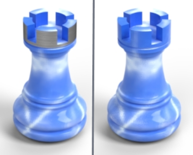
Without face appearances cleared (left), and with face Appearances cleared (right)
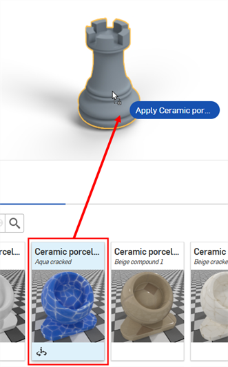
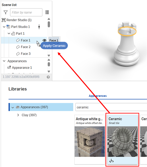
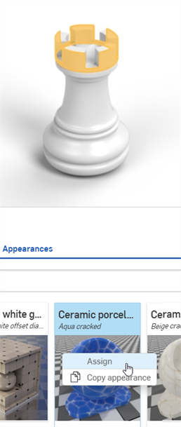
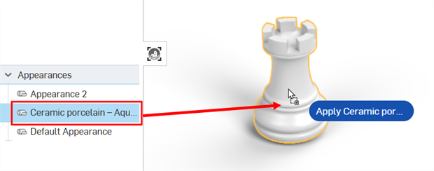
There are 6 methods to assign an Appearance to a Scene entity (Render Studio, Part Studio, Assembly, part, or face). Do one of the following:
To apply an Appearance to multiple Scene list entities, pre-select the entities in the Scene list or graphics area. Assigning or dragging and dropping the Appearance on one of the selected entities assigns the Appearance to all entities.
If dragging an Appearance, it can only be dropped on a part, not a face. To assign an Appearance to one or more faces. select the face(s) first, then right-click on the Appearance in the Appearances library and select Assign from the context menu. Alternatively, drag and drop the Appearance on one or more faces in the Scene list.
Some appearances are functions, and some of those functions cannot be added using the methods outlined below. See Using Appearance functions for more information.
Dragging and dropping an Appearance from the Appearances library onto a part or face always creates a new Appearance. This can result in multiple copies of the same Appearance in your scene. If you are assigning the same Appearance to multiple parts/faces, the recommended method is to assign the Appearance from the Appearances library to the first part/face (method 1, 2, or 3 below), and thereafter assign this Appearance from the Appearances list to any additional parts/faces (method 4, 5, or 6 below) .
When assigning an Appearance from the Appearance library, If an identical appearance exists in the Appearances list, a warning message opens (shown below). Clicking the "Use existing appearance" link assigns the Appearance from the Appearances list and does not generate a duplicate Appearance. Clicking "X" or ignoring the message results in a duplicate Appearance.

Clicking "X" or ignoring the message means it does not appear again when subsequently assigning the same Appearance from the Appearances library to another part/face.
-
Drag and drop the Appearance from the Appearances library to the selected part in the graphics area. You can only apply appearances to parts using this method, not faces.
-
Drag and drop the Appearance from the Appearances library to the selected entity in the Scene list. Using this method, you can apply the Appearance to the Render Studio, Part Studio, Assembly, part, or face:
-
Select the entity in the Scene list or graphics area, then right-click on the Appearance in the Appearances library and select Assign from the context menu:
-
If the Appearance you want to assign already exists in the Scene list (under the Appearances list), drag and drop it directly on a part in the graphics area. You can only apply appearances to parts using this method, not faces.
-
If the Appearance you want to assign already exists in the Scene list (under the Appearances list), select the entity in the Scene list or graphics area, then right-click on the Appearance and click Assign from the context menu:
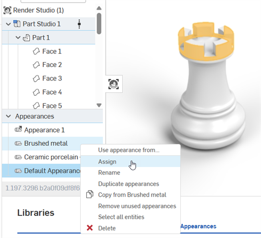
-
If the Appearance you want to assign already exists in the Scene list (under the Appearances list), select the entity in the Scene list or graphics area, then drag and drop the Appearance from the Appearances list directly to one of the selected entities in the scene list:
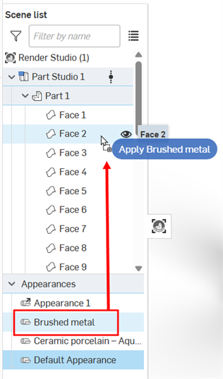
Removing an Appearance
To remove an appearance from a part or face, do one of the following:
-
Select one or more parts or faces in the Scene list, then right-click and select Unassign appearance from the Scene list context menu:
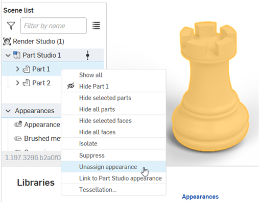
-
Right-click on the part or part face in the graphics area and select Unassign appearance from the context menu. Only one part or face appearance can be removed at a time using this method:
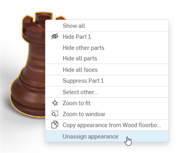
Copying and pasting Appearances
Appearances can be copied from the following locations. In all cases right-click and select Copy Appearance from the context menu:
-
An Appearance in the Appearances library
-
An Appearance in the Appearances list (under the Scene list).
-
The part or face in the Graphics area
Once the Appearance is in the clipboard it can be pasted into:
-
One or more parts or faces in the graphics area. Right click over any highlighted entity (part or face) and select Paste Appearance on entity. If multiple entities are selected, you can paste the appearance to multiple entities using the same context menu option.
-
An entity in the Scene list. The appearance can only be pasted to one entity. Pasting to multiple entities in the Scene list is not supported. However, you can paste to the top level Render Studio, which assigns the Appearance to all entities in the scene.
-
An Appearance in the Appearances list (under the Scene list). Right click over an Appearance and select Paste Appearance on [Appearance]
Alternatively, instead of using the context menu to copy/paste, you can drag and drop an Appearance in the following ways:
-
From the Appearances library to one or more parts in the graphics area. You can only apply appearances to parts using this method, not faces.
-
From the Appearance library to an entity on the Scene list (Render Studio, Part Studio, Assembly, Part, or Face).
-
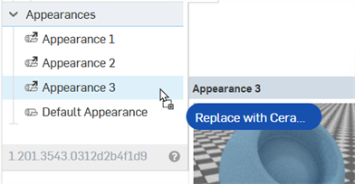
From the Appearance library to an Appearance on the Appearances list. When doing this, the Appearance in the Appearances list is replaced by the Appearance being dragged over it. Any element in the Scene list that was using the replaced Appearance now uses the new Appearance.
-
From the Appearance in the Appearances list to an entity on the Scene list (Render Studio, Part Studio, Assembly, Part, or Face).
-
From one Appearance in the Appearances list to another Appearance in the Appearances list. When doing this, the Appearance in the Appearances list is replaced by the Appearance being dragged over it. Any element in the Scene list that was using the replaced Appearance now uses the new Appearance.
-
From the Appearances list to one or more parts in the graphics area. You can only apply appearances to parts using this method, not faces.
You can also use ctrl/cmd+c to copy and ctrl/cmd+v to paste Appearances, provided your cursor is in the right location to allow it. For example, copy when hovering over an Appearance in the Appearances library and paste when hovering over a selected face or part in the graphics area.
Things to keep in mind:
-
Copying and pasting Appearances follows the same logic used when adding an Appearance. See Adding an Appearance to a Scene list entity.
-
If the target Appearance was not previously renamed, the source Appearance name is used. If the target Appearance was previously renamed, this name is retained when the source Appearance replaces the target Appearance.
-
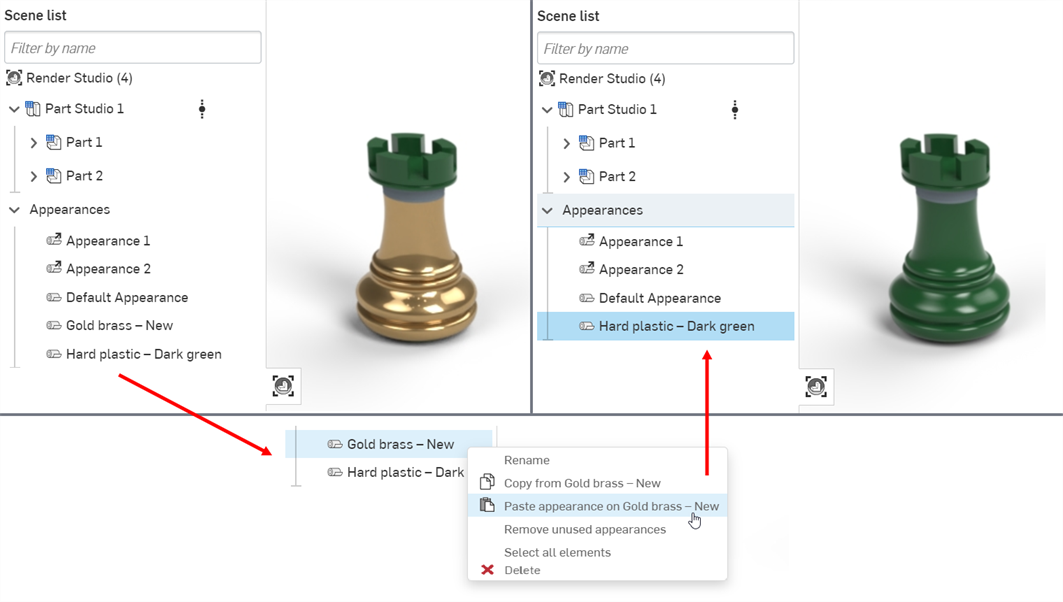
Copying an Appearance from the Appearances list (source) and pasting it to another Appearance on the Appearances list (target) replaces the target Appearance and removes it from the Appearances list. All entities that were previously assigned the target Appearance are now assigned the source Appearance.
For example, in the image below the Hard plastic — Dark green Appearance is copied and pasted into the Gold brass — New Appearance. This removes the Gold brass — New Appearance from the Appearances list, and any previous entities which were assigned the Gold brass — New Appearance are now assigned the Hard plastic — Dark green Appearance.
-
If pasting to a linked Appearance, the link is broken and the new Appearance replaces the linked Appearance.
Working with favorites
Any user can add any Appearance to the My favorites folder. If you are in a company (for Pro plans) or enterprise (for Enterprise plans) and have the required permissions to edit the company favorites, you can add any Appearance to the Company favorites folder. Both these folders help you catalog and have quick access to frequently-used Appearances.
These folders are not visible if they do not contain any Appearances. By default, you do not see them listed in the Appearances library's folders list.
An appearance can be placed in both folders.
To add an Appearance to the My favorites or Company favorites folder:
-
Locate an Appearance you would like to add to the My favorites or Company favorites folder.
-
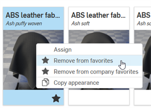
Right-click on the Appearance and select Add to favorites or Add to company favorites:
-
The Appearance is now located in the My favorites or Company favorites folder at the top of the Appearances library's folders list. Favorite Appearances display a star icon (
 ) at the lower right corner of their thumbnail.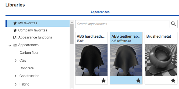
To remove an Appearance from a favorites folder, right-click on it and select Remove from favorites or Remove from company favorites:
Transforming an Appearance
Transforming an Appearance is similar to transforming a part, however, only the Appearance is transformed. The part remains static. This example uses a wood table. The wood appearance is transformed to make the table look more realistic.
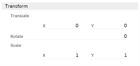
Appearances generally have a transform submenu in the Appearance panel, with x and y axis values for Scale and Translate, and a degree value for Rotation, as shown below:
-
Translation - Moves the selection along the x and y axis, according to the origin point of the selection. Measurement units are in meters, and are negative or positive numbers.
-
Rotation - Rotates the angle of the texture about the center point of the selection's z axis, from -360 to +360 degrees.
-
Scale - Scales the selection up (larger) or down (smaller), along the x and y axis, according to the center point of the selection. Measurements are based on the selection's original size. For example, a Scale of 1.000 x by 1.000 y means that the scale is 100% of the part's original size. Fractional numbers from 0.001 to 1 reduce the size of what is selected.
-
Create an Assembly of a table top and four legs, so there are five assembled parts.
-
Create a Render Studio scene and insert the table Assembly.
-
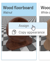
Select the table top in the Scene list. Search Floorboards in the Appearance library. Right click on the Wood floorboard — Walnut Appearance and select Assign from the context menu. The Appearance is applied to the table top:
-
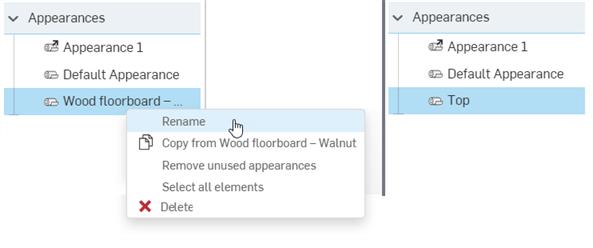
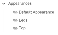
In the Scene list, under Appearances right-click on the Wood floorboard Appearance and select Rename from the context menu. Rename the Appearance "Top". This also renames the Appearance in the Appearances panel on the right.
-
In the Scene list, deselect the table top, and multi-select (Ctrl/Cmd+Select) the table legs. Right click on the Floorboards - Walnut and select Assign from the context menu. The appearance is applied to all four table legs.
-
In the Scene list, under Appearances right-click on the Wood floorboard Appearance and select Rename from the context menu. Rename the Appearance "Legs".
-
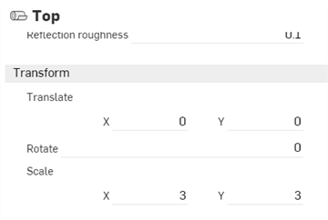
Click on the Top appearance thumbnail to select it. In the Appearance panel's Transform submenu on the right, enter a scale of 3 x 3. This removes the floorboard grooves by translating the appearance pattern larger than the table:
-
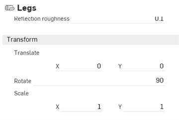
Click the Legs Appearance thumbnail in the Appearance library. Enter a Rotation measurement of 90 degrees in the Appearance panel's Transform submenu. This creates vertical planks of wood along the table leg appearance. Since the Legs appearance in the Scene appearances folder is associated with all four legs, they are all transformed simultaneously as a group:
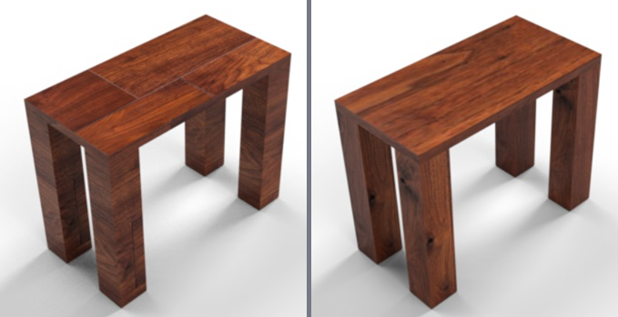
The Table model with default Walnut - Floorboards appearance (left), and after transforming the appearances (right).
Adjustments may not always yield the same results shown in the sample image here, especially with Transform options, which depend largely on model size. The Appearance may require a scale larger or smaller than X: 3 by Y: 3.
Optionally, for more granular control of Appearance transformations, apply the same or different appearances to each part face and then transform each face appearance separately. To do this, click on the arrow to the left of the part name in the Scene list to expand all the part's faces.
Using Appearances in the Scene list
When an appearance is applied to a part or face in a scene, it is placed in the Appearances section at the bottom of the Scene list. This helps keep track of appearances used in the scene. Apply the same appearance to multiple parts. When any part or face that uses the appearance is selected, and its appearance edited in the Appearances panel, all other parts and faces using the appearance are updated simultaneously. There is no need to individually update each part or face appearance.
-
Add an appearance to a part or face. In the image below, a blue cloth material appearance is added to one of the shoes.
-
Rename the appearance. This helps to locate the appearance in the Scene list later, especially if the scene is complex, with many appearances.
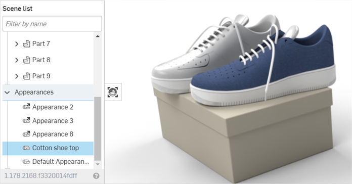
-
Locate the Appearance in the Scene appearances folder in the Appearances library, and assign the appearance to as many other parts or faces in the scene:
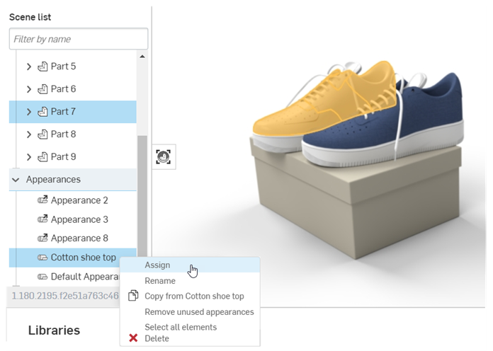
-
Edit the Appearance using the Appearances panel. For example, in the image below, the color of the shoe fabric is changed to gray. Notice that both shoes are updated with the new color attribute, even though only one shoe is selected:
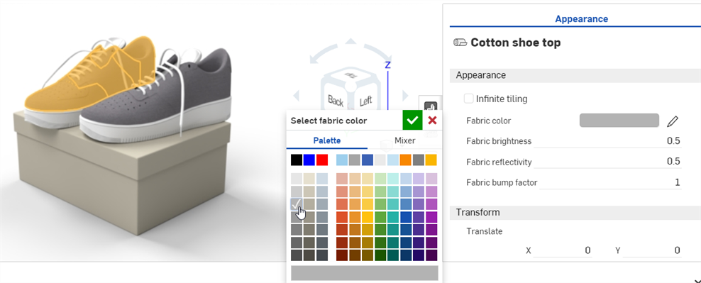
Adding a texture
Apply a texture to one of the part's appearance parameters. This procedure explains how to apply a texture to the part's Diffuse roughness parameter.
-
In the Scene list or graphics area, select the part.
-
Expand the Base submenu in the Appearance panel, if it is not already expanded.
-
In the Appearances library, select the Appearance functions folder.
-
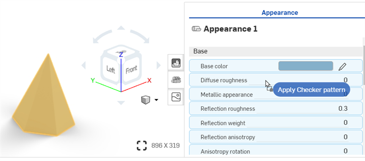
Locate the Checker pattern function, then click and drag it from the Appearances library and drop it on top of the Base submenu's Diffuse roughness parameter in the Appearance panel on the right.
-
The texture is applied and automatically opens in the Appearances panel. This is verified by the hierarchical breadcrumb trail at the top of the Appearance panel. Adjust the Checker pattern's parameters to different specifications using the submenus in the Appearance panel:
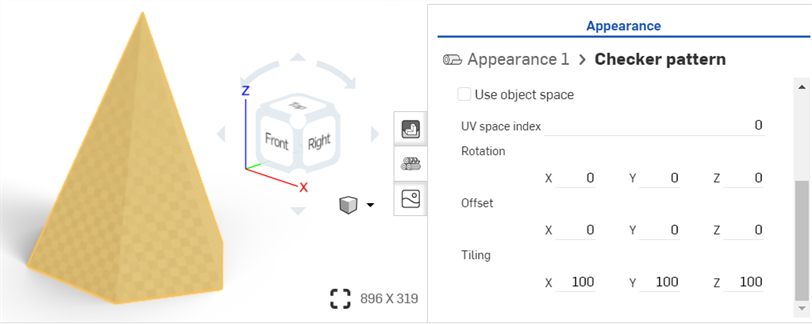
-
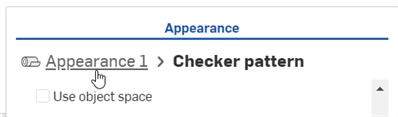
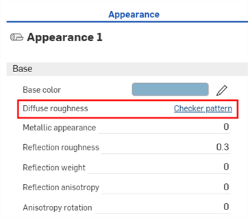
Click the Appearance 1 breadcrumb link at the top of the Appearances panel (shown in the first image below) to return to the part's Appearance panel. To edit the texture again, click its link next to the Diffuse roughness parameter (shown in the second image below):
Before dropping the texture, notice that many of the Appearance parameters are highlighted in blue. This indicates the texture can be applied to any of these parameters. Drop the thumbnail on the parameter of choice. See Using Appearance functions for more information.
Adding a custom image as a texture
This procedure explains how to apply a custom image (PNG or JPG, for example) as a texture to a face or part appearance's Base color parameter. You can, however, modify this procedure to apply the texture to a number of other appearance parameters, as required.
An alternative way to apply a custom image as a texture is to use the appearance parameter's context menu in the Appearance panel. See Applying a texture to a parameter.
-
If your texture image is not already imported into your document, click the Insert new tab icon (
 ) and select Import: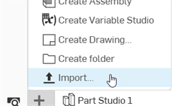
-
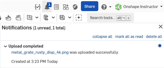
You will receive a notification when the file is imported:
-
In the Scene list or graphics area, select the faces and/or part.
-
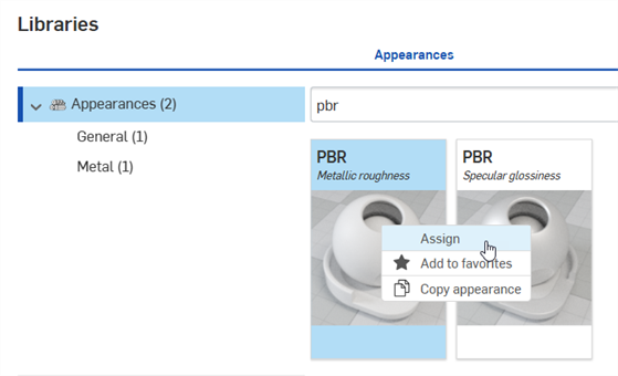
Locate the PBR - Metallic roughness appearance in the library. Right-click on it and select Assign from the context menu:
-
From the Appearance panel, set some basic parameters on the appearance, such as Metallic, Brightness, Opacity, and more, to your requirements.
-
Locate, then drag and drop the Import bitmap file - Bitmap texture function on the Base color parameter of the PBR - Metallic roughness appearance in the Appearance panel:
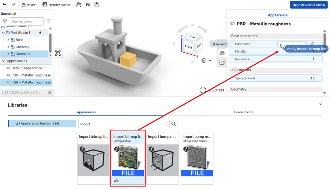
Before dropping the texture, notice that many of the Appearance parameters are highlighted in blue. This indicates the texture can be applied to any of these parameters. Drop the thumbnail on the parameter of choice. See Using Appearance functions for more information.
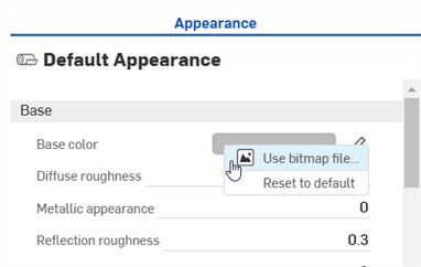
Alternatively, right-click on the parameter and select Use bitmap file, then select the file you imported to apply it to the parameter:
-
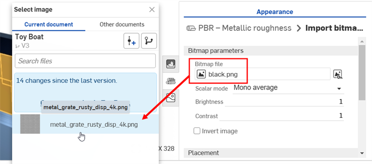
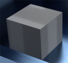
Click the default black.png Bitmap file and select the texture image you imported into your document earlier (shown in the first image below). The texture is applied to the selected faces and/or part (shown in the second image below):
If you import the texture after you have already created the Render Studio tab, you will need to create a version of your document in order to access the Texture from the Select image dialog.
-
Modify the Rotation, Offset, and Tiling of the texture on the image to your specifications.
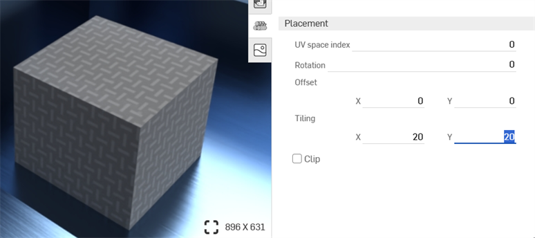
Setting the Tiling to x: 20; Y: 20
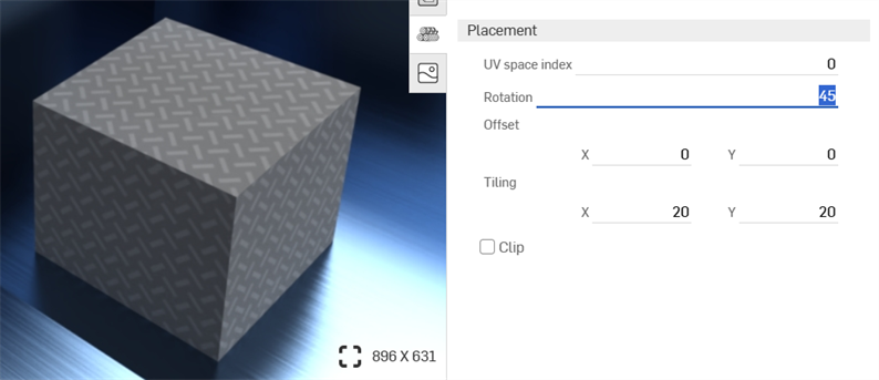
Setting the Rotation to 45 degrees
-
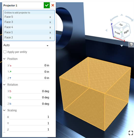
Click the Projector icon (
 ) on the toolbar to open the Projector dialog.
 -
In the Entities to add projector to, select the faces and/or part to which you applied the texture.
-
Select the Position, Rotation, and Scaling options to your specifications.
Adding a bump texture
A bump texture (or bump map) simulates a part's surface texture. Normal maps are a specific type of texture where bump details (wrinkles, grooves, patterned divots, and the like) are added to the model. When light is reflected off the surface, real geometry is simulated.
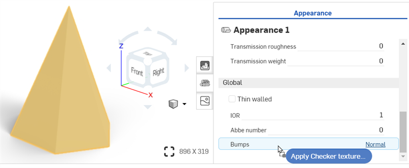
A bump texture is not applied directly to the part. It is applied to the part appearance's Bumps parameter.
-
Select the part in the Scene list or graphics area.
-
Expand the Global submenu in the Appearance panel, if it is not already expanded.
-
In the Appearances library, select the Appearance functions folder.
-
Locate the Checker texture bump map function, then click and drag it from the Appearances library and drop it on top of the Bumps parameter in the Appearance panel on the right.
-
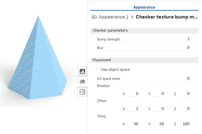
Once applied, adjust the bump texture parameters using the Appearance 1 > Checker texture bump map panel submenus:
-
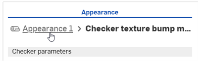
Click the Appearance breadcrumb link at the top of the Appearance panel (shown in the first image below) to return to the part's Appearance panel. To edit the bump texture again, locate it in the Global submenu and click on its link (shown in the second image below):
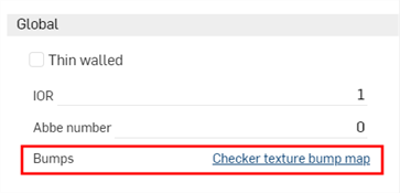
Before dropping the bump texture, notice that only the Bumps parameter is highlighted in blue. This indicates the bump texture can only be applied to this parameter. See Using Appearance functions for more information.
Adding a custom bump texture
A bump texture (or bump map) simulates a part's surface texture. Normal maps are a specific type of texture where bump details (wrinkles, grooves, patterned divots, and the like) are added to the model. When light is reflected off the surface, real geometry is simulated.
A bump texture is not applied directly to the part. It is applied to the part appearance's Bumps parameter.
-
Select the part in the Scene list or graphics area.
-
Expand the Global submenu in the Appearance panel, if it is not already expanded.
-
In the Appearances library, select the Appearance functions folder.
-
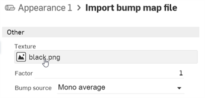
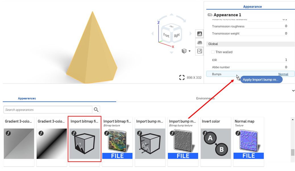
Locate the Import bump map file function, then drag and drop it on top of the Bumps attribute on the Global submenu.
-
In the Appearance panel, click the Bitmap file (black.png). This opens the Select image dialog:
-
Do one of the following:
-
Select a bump map file from the Current document
-
Click Other documents to locate a file in another Onshape document
-
Click the Import link at the bottom of the dialog to locate a bump map file (.jpg or .png) from your computer. When selected, click the Open button:
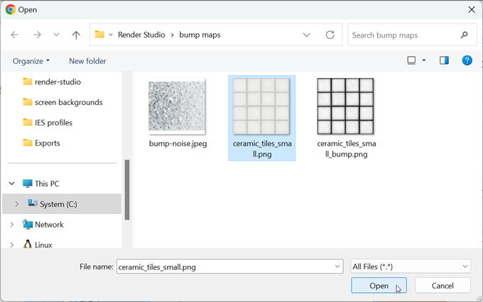
Once the notification indicates the upload is complete, you will not yet see the image in the Select image dialog. This is because the Render Studio scene is a snapshot of the part, Part Studio, or Assembly at the time of import, and this image is brought into the Onshape document post-import. A new version is now required, in order to update the scene. Click the Create a version in [Document name] link in the Select image dialog:
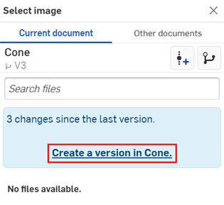
The Create version dialog opens. Enter the version information and click the Create button.
-
-
Once the new version is created, the .ies file is located in the Select light profile. Click it to select it:
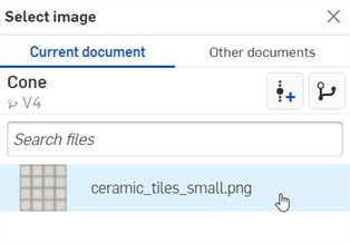
-
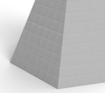
Once selected, the file is loaded into the Bitmap file field. Use the Bitmap and Placement submenus to edit the bump texture parameters:
-
Tiling - Control the scale of the texture on the part. Larger numbers reduce the texture size (more tiles), while lower numbers increase the size of the texture (fewer tiles).
-
Clip - If enabled, the texture does not repeat and anything outside the texture shows as flat.
-
Offset - Control the position of the texture on the part
-
Rotation - Control the rotation of the texture on the part, in degrees.
-
Bump mode - Define how the texture is evaluated to create the bumps.
-
Bump strength - Control the intensity of the Bump map tiling.
Alternatively, use the Import bitmap file function (shown in the red box below) for more complex texture editing capabilities. Complex graphs of texture placement functions are connected to file_texture maps.
Before dropping the bump texture, notice that only the Bumps parameter is highlighted in blue. This indicates the bump texture can only be applied to this parameter. See Using Appearance functions for more information.
If you don't see the Create version link in the Select image dialog, click the Create version button ( ) on the Document panel to open the Create version dialog. Create the new version. Close and reopen the Select image dialog. The imported image should now be available.
See Importing files for more information about uploading files.
Creating transparency
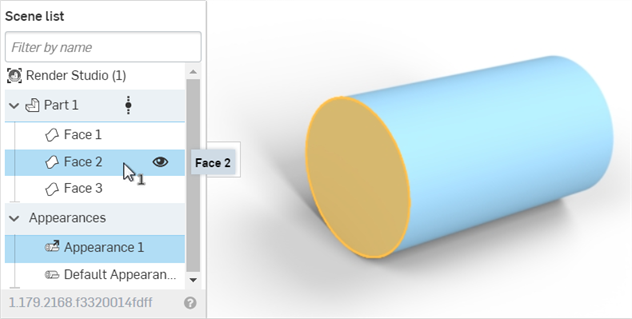
To create a transparency for a part face:
-
Select the part or face in the Scene list or graphics area.
-
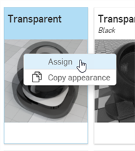
Search the Appearance library for Transparent. Right-click on the transparent thumbnail, and click Assign:
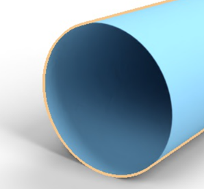
In the example below, the transparency is applied to the cylinder's front face. The face remains. but is now transparent through to the other faces:
Adding a sticker
A common task is to place a logo or text on a surface or part.
While the approach outlined here is a valid way to add a sticker to a surface or part, Render Studio now automatically imports Decals when a Part Studio that uses Decal features is inserted. This is the recommended approach. See Working with Decals for more information.
-
Create a model and bring it into a Render Studio scene.
-
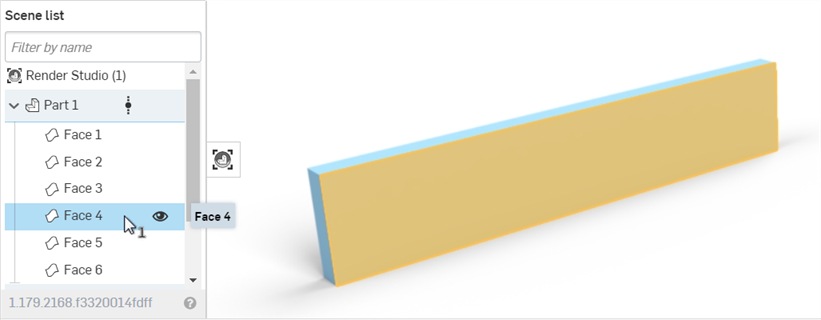
Select the part or face in the Scene list or graphics area:
-
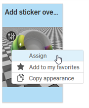
In the Appearances library, search for sticker, then right=click on the Add sticker overlay thumbnail and select Assign from the context menu:
-
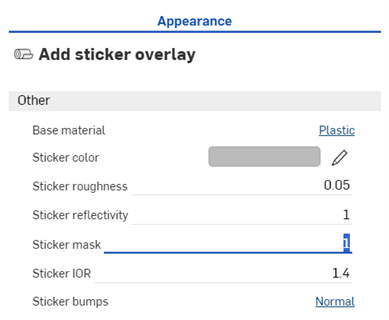
In the Appearance panel, set the Sticker mask to 1:
-
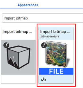
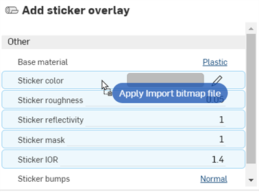
In the Appearances library > Appearance functions folder, Locate the Import bitmap file — Bitmap texture function (first image below), then drag and drop it over the Sticker color parameter in the Appearance panel (second image below). This allows selection of a file to be used for the sticker.
-
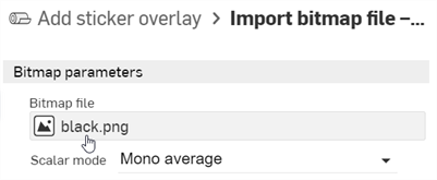
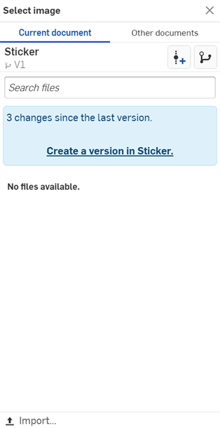
Click on the Bitmap file (black.png) to open the Select image dialog.
-
Do one of the following:
-
Select a bump map file from the Current document
-
Click Other documents to locate a file in another Onshape document
-
Click the Import link at the bottom of the dialog to locate a bump map file (.jpg or .png) from your computer. When selected, click the Open button:
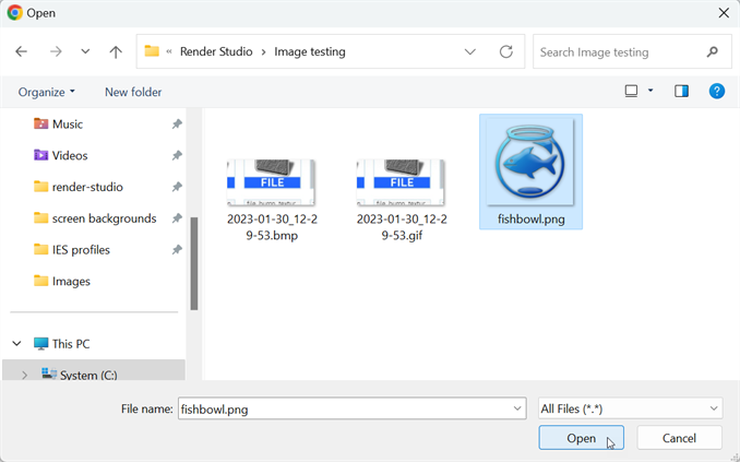
Once the notification indicates the upload is complete, you will not yet see the image in the Select image dialog. This is because the Render Studio scene is a snapshot of the part, Part Studio, or Assembly at the time of import, and this image is brought into the Onshape document post-import. A new version is now required, in order to update the scene. Click the Create a version in [Document name] link in the Select image dialog:
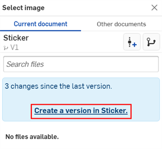
The Create version dialog opens. Enter the version information and click the Create button.
-
-
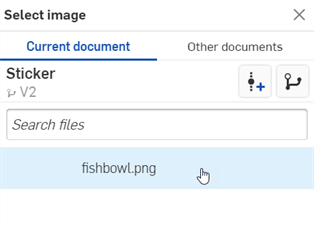
Once the new version is created, the sticker file is located in the Select image dialog. Click it to select it:
-
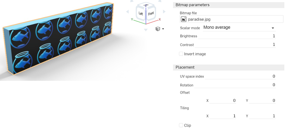
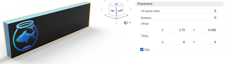
Once selected, the file is loaded into the Bitmap file parameter. Use the Placement options to set up the proper location for the sticker. By default, the Tiling is set to a repeating 1 x by 1 y, and is not offset or rotated:
-
Set Tiling to 6 x by 6 y to increase the image size, and check the Clip option, which forces the sticker not to repeat. Here, the sticker is also offset to show at the far left of the face. Write down these settings, as they are needed later, when applying a mask.
-
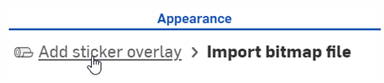
At the top of the Appearance panel, click the Add sticker overlay link. This returns the Appearance panel to the parent sticker.
-
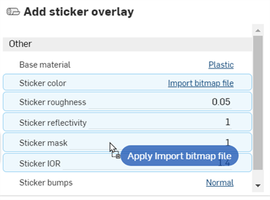
Apply the same bitmap file (and settings) to the mask. Drag the Import bitmap file — Bitmap texture function from the Appearance library > Appearance functions folder, and drop it on the Sticker mask parameter in the Add sticker overlay Appearance in the Appearance panel. In the Placement submenu, enter the exact same settings entered previously for the sticker file: Tiling, Clip, Offset, and Rotation.
-
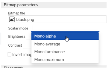
Select Mono alpha in the Scalar mode dropdown in the Bitmap parameters submenu:
-
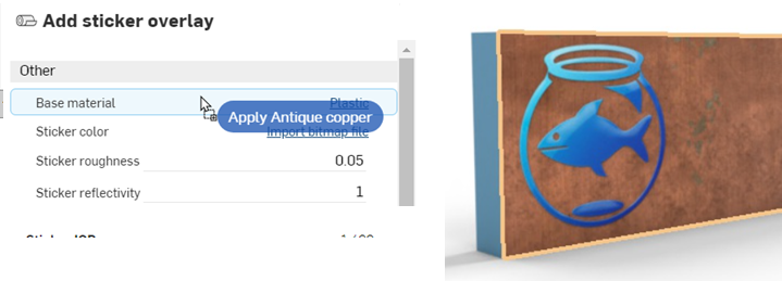
The default Base material parameter is plastic; however, any Appearance can be applied to the face, without affecting the sticker. Locate an Appearance from the Appearance library and drag and drop it on the Base material parameter to add it to the face:
-
If desired, the face can be made transparent, while keeping the sticker in place, as shown below:
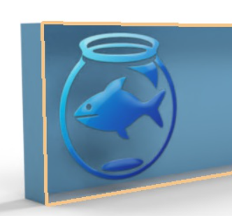
Since even stickers have a small amount of height to them, create a face that is .1 mm in depth above the main face where the sticker is applied when the part is modeled. Then apply the sticker to this face, as outlined below. This creates more realistic sticker edges.
If you don't see the Create version link in the Select image dialog, click the Create version button () on the Document panel to open the Create version dialog. Create the new version. Close and reopen the Select image dialog. The imported image should now be available.
See Importing files for more information about uploading files.
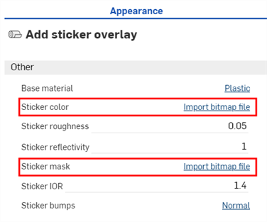
To alter the sticker and/or mask settings, click the Sticker color or Sticker mask's Import bitmap file link, respectively, then adjust the settings. To keep both sticker and mask in sync, both sets of settings must be updated to match:
See the following topics for more information: