Appearance Functions

Only available for
Available in: Render Studio
Functions are a special type of appearance that perform a specific action on a part's appearance parameter. When a scene is created, every part has a default set of appearance parameters, viewable in the Appearance panel on the right.
All functions are located in the top-level Appearance functions folder. Additionally, functions are indicated by a function icon ( ) at the top left corner of the Appearance thumbnail:
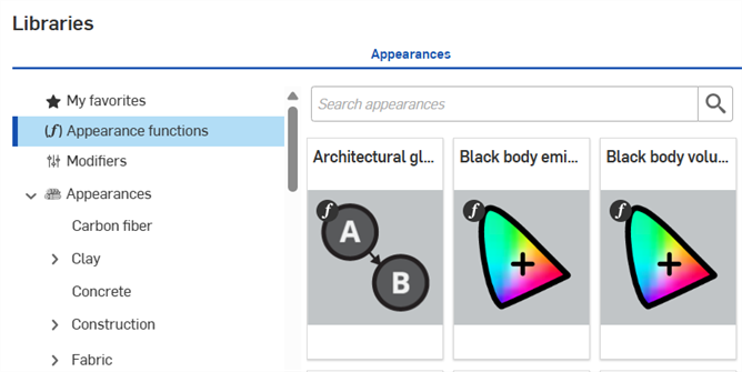
 Appearance functions table
The following table outlines all appearance functions in the Appearances library:
| Function name | Function subheading | Description |
| Spectral index of refraction (ior) | Abbe number ior | Apply spectral index of refraction (ior) to parameters that accept a color. Adjust abbe number (dispersion control; 0 = off; 25-85 = dispersive materials), and ior (volumetric refraction that also influences non-metallic material reflectivity) parameters. For example, If you are provided with an abbe number that corresponds to glass or gem stones, you can input it using this function. |
| Architectural gloss to rough | Convert glossiness parameter to roughness parameter, semantics according to the Iray v2 Arch+Design implementation | |
| Black body emission | Color of a black body emission that can be applied to any color parameter. Adjust blend value, color temperature 1 and 2. Useful for emissive appearances. | |
| Blend color layers | Texture layering functionality similar to the functionality known from painting programs. Blend 2 texture layers; select from 28 unique blend modes, applied to any base, global, or transmission appearance parameter (except bumps/normal). Adjust base color, layers (add and blend/weight additional color arrays), and mono source parameters. | |
| Blend normals | Blend the output of functions which return two normals. Can be used to blend two textures for sticker-like situations where a detail normal map is applied to a base normal map, or the procedural bump/normal mapping functions (for example, check_bump_texture). | |
| Coordinate projection | Apply texture coordinate system based on projection functions to global bumps or other normal appearance parameter. Adjust coordinate system (UVW, world, or object), projection transform (TRS or matrix), translation, rotation, scale, projection type (9 types), and texture space parameters. | |
| Coordinate source | Apply world or object coordinates, or defined texture spaces to global bumps or other normal appearance parameter. Adjust coordinate system (UVW, world, or object), and texture space parameters. | |
| Import bump map file | Apply a heightfield-style normal bump map image file to global bumps or other normal appearance parameter. Add texture via image file selection. Adjust wrap, bump source, animation, crop, normal, B-spline, factor, clip, and texture coordinates parameters. | |
| Import bitmap file | Apply 2D bitmap texture, stored in an image file, to any base, global, or transmission appearance parameter (except bumps/normal). Adjust file contrast, brightness, image inversion, and scalar mode. | |
| Flake noise texture bump map | Flake noise texture bump map applied to global bumps or other normal appearance parameter. Adjust maximum size, metric, noise type, normal, scale, strength, and UVW parameters. | |
| Flake noise pattern | Flake noise pattern applied to any base, global, or transmission appearance parameter (except bumps/normal). Adjust density, intensity, maximum size, metric, noise type, scale, and UVW parameters. | |
| Gradient 3-color/position bump map | Apply a 3-color/position gradient to a bump map. Gradient is linear, square, box, diagonal, 90/360 degree, or radial, and is applied to an appearance parameter. | |
| Gradient 3-color/position texture | Apply a 3-color/position gradient that is linear, square, box, diagonal, 90/360 degree, or radial gradient, to an appearance parameter. | |
| Rotation translation scale | Apply transform matrix from Euler rotation, translation and scale, to a coordinate projection > projection transform appearance parameter. Adjust rotation, scaling, and translation parameters. | |
| Spectral index refraction | Apply refraction spectral index using Sellmeier coefficients to parameters that accept color (spectral) ior. Adjust Sellmeier B and Sellmeier C parameters to determine the dispersion of light in the appearance. | |
| Tangent space normal texture | Converts bitmap file color values to tangent space vector values applied to global bumps or other normal appearance parameter. Add texture via image file selection. Adjust wrap (U, V), animation (wrap, start time, crop, FPS), crop (U, V), flip tangent (U, V), scale, factor, clip, offset, and UVW parameters. | |
| Tile texture bump map | Tile texture bump map applied to global bumps or other normal appearance parameter. Adjust grout (height, width, roughness), special column (height factor, index, width factor), special row (index, width factor), normal, odd row offset, number (columns, rows), factor, missing tile amount, seed, random row offset, tile brightness variation, and UVW parameters. | |
| Tile pattern | Tile pattern applied to any base, global, or transmission appearance parameter (except bumps/normal). Adjust grout (color, height, width, roughness), tile (color, brightness variation), special column (height factor, index, width factor), special row (index, width factor), odd row offset, number (columns, rows), missing tile amount, seed, random row offset, and UVW parameters. | |
| Coordinate transform | Apply texture transform by coordinate matrix to global bumps or other normal appearance parameter. Adjust coordinate (position, tangent U, tangent V), transform (TRS or matrix), translation, rotation, and scale parameters. | |
| Black body volume emission | Blackbody emission intensity for a field of heated particles that can be applied to any color parameter. Adjust blend value, color temperature 1 and 2. | |
| Volume coefficient | Compute a volume coefficient based on distance and value that can be applied to any color parameter. Adjust distance and tint. | |
| Worley noise texture bump map | Worley noise texture bump map applied to global bumps or other normal appearance parameter. Adjust size, mode, normal, apply marble, factor, metric, UVW, apply dent, step threshold, noise (distortion, bands, high/low threshold), and edge parameters. | |
| Worley noise pattern | Worley noise pattern applied to any base, global, or transmission appearance parameter (except bumps/normal). Adjust size, 2 colors, mode, apply marble, metric, UVW, apply dent, step threshold, noise (distortion, bands, high/low threshold), and edge parameters. | |
| Get blue color | Gets the blue component of a color as a float (gets the number from a color). Can be used for any color input, but an input connected to a texture is common. For example, if you have a texture that encodes three different scalar properties that can be routed to different parameters. | |
| Get green color | Gets the green component of a color as a float (gets the number from a color). Can be used for any color input, but an input connected to a texture is common. For example, if you have a texture that encodes three different scalar properties that can be routed to different parameters. | |
| Get color component | Gets the rgb (red/green/blue) component of a color as a float (gets the number from a color). Can be used for any color input, but an input connected to a texture is common. For example, if you have a texture that encodes three different scalar properties that can be routed to different parameters. | |
| Color intensity | Returns the intensity of the input color | |
| Get red color | Gets the red component of a color as a float (gets the number from a color). Can be used for any color input, but an input connected to a texture is common. For example, if you have a texture that encodes three different scalar properties that can be routed to different parameters. | |
| Convert color to vector | Converts a color to a float3 | |
| Cosine 1d | Returns 1 + cos( ( input + modifier / 2 ) * 50.0)) / 2.0. Useful to generate oscillations in an input value that is driven by texture coordinates, for example. | |
| Vector length | Returns the length of the input vector. Used between other functions to convert output, making the output compatible for other types of parameters. | |
| Convert vector to color | Converts a float3 to an rgb (red/green/blue) color. Used between other functions to convert output, making the output compatible for other types of parameters. | |
| Convert vector to floats | Converts a float3 to three floats. Used between other functions to convert output, making the output compatible for other types of parameters. | |
| Invert color | Returns the inverse of the input color | |
| Convert Kelvin to color | Converts input from kelvin to a color | |
| Scale color | Scales the input color by the scale RGB color. Apply to any color parameter. Adjust color scale and input color parameters. | |
| Sine 1d | Returns 1 + sin( ( input + modifier / 2 ) * 50.0)) / 2.0. Useful to generate oscillations in an input value that is driven by texture coordinates, for example. | |
| Blend colors | Blend 2 color layers to any base, global, or transmission appearance parameter (except bumps/normal). Use one of 28 blend modes to blend the two color layers. Adjust color 1 and 2, linear blend, blend mode, and blend weight. | |
| Blend normals | Blend two normals or apply a detail normal map to global bumps or other normal appearance parameter. Apply base and detail normals, and adjust each of their weight parameters. | |
| Checker texture bump map | Apply checker texture bump map to global bumps or other normal appearance parameter. Adjust placement (UV space index, use object space, tiling, offset, rotation), blur, and bump strength parameters. | |
| Checker pattern | 3d texture | Apply checker pattern to any base, global, or transmission appearance parameter (except bumps/normal). Adjust placement (UV space index, use object space, tiling, offset, rotation), blur, and 2 pattern colors parameters. |
| Import bump map file | Bitmap bump texture | Apply 2D bump map, stored in an image file, to global bumps or other normal appearance parameter. Adjust file bump mode and bump strength. |
| Import bitmap file | Bitmap texture | Apply 2D bitmap texture, stored in an image file, to any base, global, or transmission appearance parameter (except bumps/normal). Adjust file contrast, brightness, image Inversion, and scalar mode. |
| Bump map | Flow noise texture | Apply flow noise texture bump map to global bumps or other normal appearance parameter. Adjust placement (tiling, offset, rotation), progressive v offset/u scale, level scaling, bump strength, billowing, levels, level intensity gain, and phase offset parameters. |
| Pattern | Flow noise | Apply flow noise pattern to any base, global, or transmission appearance parameter (except bumps/normal). Adjust placement (tiling, offset, rotation), 2 colors, level progressive v motion/u scale, billowing, levels, level intensity gain, and phase offset parameters. |
| Normal map | Texture | Apply tangent space normal map to global bumps or other normal appearance parameter. Adjust uv space index, tiling, flip v, clip, offset, rotation, strength, and normalmap file (via file selection). |
| Bump map | Perlin noise texture | Apply perlin noise texture bump map to global bumps or other normal appearance parameter. Adjust placement (tiling, offset, rotation), bump strength, billowing appearance, levels, and upper/lower threshold parameters. |
| Pattern | Perlin noise | Apply perlin noise pattern to any base, global, or transmission appearance parameter (except bumps/normal). Adjust placement (tiling, offset, rotation), 2 pattern colors, billowing appearance, levels, and upper/lower threshold parameters. |
| Bump map | Cellular noise texture | Apply cellular noise texture bump map to global bumps or other normal appearance parameter. Adjust placement (UV space index, use object space, tiling, offset, rotation), bump strength, cell shape, and upper/lower threshold parameters. |
| Pattern | Cellular noise | Apply cellular noise pattern to any base, global, or transmission appearance parameter (except bumps/normal). Adjust placement (UV space index, use object space, tiling, offset, rotation), cell (type, shape), 2 pattern colors, and upper/lower threshold parameters. |
| Data is valid | ||
| Data lookup color | ||
| Data lookup float | ||
| Data lookup float2 | ||
| Data lookup float3 | ||
| Data lookup integer | ||
| Data lookup uniform color | ||
| Data lookup uniform float | ||
| Data lookup uniform float2 | ||
| Data lookup uniform float3 | ||
| Data lookup uniform integer | ||
| FFF 3D print | Texture | Texture to simulate layer lines of a Fused Filament Fabrication (FFF) 3D print. Used to darken crevices between layer lines to give the impression of self-shadowing. Adjust base color, crevice color, layer height, extrusion width and infill. |
| FFF 3D print | Bump map | Simulates layer lines of a Fused Filament Fabrication (FFF) 3D print via bump map. Normals that differ greatly from the underlying geometry may be generated. Enabling Smooth coarse shdows option for the scene is recommended. Adjust layer height, extrusion width and infill. |
| Triplanar | Texture | Apply three 2D bitmap texture files, stored in image files, to any base, global, or transmission appearance parameter (except bumps/normal). Adjust tiling, offset, and rotation for each file, as well as placement (use object space, rotation of origin), and common parameters (blend range, mean color). |
| Triplanar | Triplanar normal map texture | Apply three 2D normal map texture files, stored in image files, to the rotation of origin parameter of the Triplanar function. Adjust tiling, offset, and rotation for each file, as well as placement (use object space, rotation of origin), and common parameters (blend range, strength). |
Notes
-
Some functions cannot be assigned to parts directly. If the right-click context menu options are unavailable from the appearance thumbnail, or the context menu does not open when the appearance thumbnail is dragged and dropped on the part in the scene, this indicates the appearance is a function.
-
See Appearance library - Functions for a complete list of all functions and a short description of each.
-
Some functions can only be applied to parameters in the Appearance panel, and depend on what is selected in the Scene list.
-
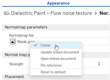
For the Normal map — texture function, texture resources can optionally be treated as containing linear color data. When the texture represents something other than a color (for example a tangent space normal map or scalar data such as roughness) then it should be treated as linear to ensure the color data is correctly processed.
For normal map textures specifically, the Linear option is automatically selected to ensure valid results. For other parameters you can choose how you want to interpret the colors using the Linear options on the context menu for the texture resource (see below):
-
To apply an Appearance function to an Appearance parameter while the Appearances library is in the right panel, drag the Appearance function on top of the Appearance panel icon and hold until it opens. Then drop the Appearance function on the parameter in the panel.
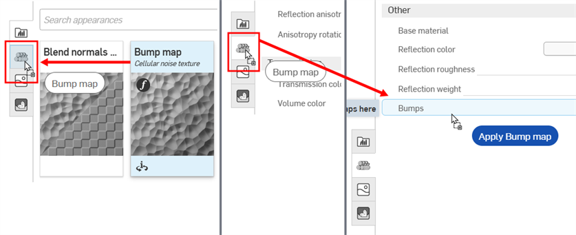
Dragging the Bump map Appearance function over the Appearance panel icon (left). The Appearance panel opens (middle). While still holding, drag the Bump map Appearance function on top of the Bumps parameter in the Appearance panel (right).
Example 1: 3D checker texture and 3D Checker texture -- bump mapping
To apply a function to the part's Appearance parameter:
-
Select the part in the Scene list or graphics area. The Appearance panel displays the part's default Appearance parameters.
-
Select the Appearance functions folder In the Appearances library
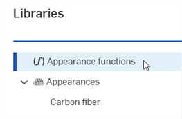
Locate the Checker pattern — 3D texture and Checker texture bump map functions. They are both used in this example. The lower box part in the following model is used for reference:
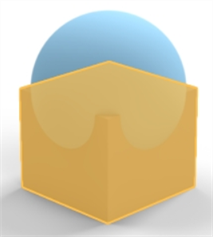
-
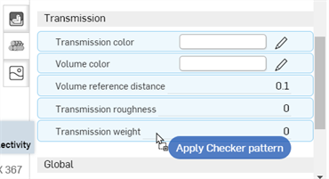
Drag the Checker pattern — 3D texture function over the Appearances panel. Before dropping, notice that many of the Appearance parameters are highlighted in blue. This indicates this function can be applied to any of these parameters. The function is applied to the parameter beneath the mouse cursor. Drop the parameter on the Transmission weight parameter in the Transmission submenu:
-
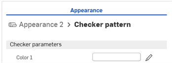
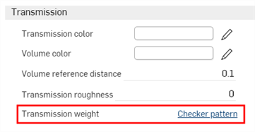
The texture function is applied and automatically opens in the Appearances panel. This is verified by viewing the hierarchical breadcrumb trail at the top of the Appearances panel (shown in the first image below). Click on the Appearance 2 link in this breadcrumb trail, and the Appearance for the part opens, where the link to the texture function next to the Transmission weight parameter is displayed (shown in the second image below).
-
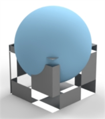
The texture function acts as a mask for light transmission through the part (the checker texture is the function applied to the Transmission weight parameter of the part's Appearance). Anywhere the checker pattern is white, light shows through. Anywhere the checker pattern is black, the base part color shows through. The checker pattern is the part's light transmission mask:
-
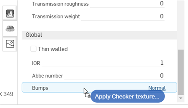
Alternatively, drop the Checker texture bump map function on the Bumps parameter in the Appearance panel's Global submenu. The Bumps parameter is the only one to turn blue, indicating this parameter is the only one that accepts the Checker texture bump map function:
-
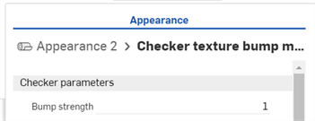
The Checker texture bump map function is applied to the Bumps parameter, shown below:
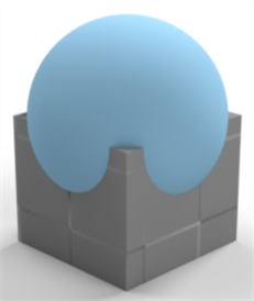
See Add a bump texture and Add a custom bump texture for more information.
Example 2: Invert Color
The next example applies an Invert color function to the Part's base color. Apply this method to any appearance color parameter, and use it to invert the color.
-
Select the part. In this example, the sphere is selected.
-
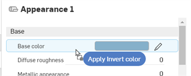
Drag and drop the Invert color function on the Base color in the part's Base submenu on the Appearance panel:
-
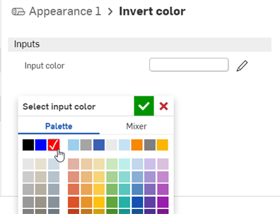
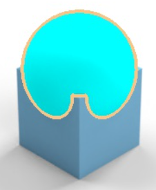
The Invert color function opens under the Appearance panel. Click the Input color swatch and select a color. The inverse of that color is used for the Part's base color. In the following example, selecting red creates a cyan base color, since cyan is the inverse of red:
Example 3: Surface blender and Gradient3-color/position texture
This example uses the Surface blender function to blend between two surface appearances. Once completed, an additional function (Gradient3-color/position texture) is applied to the first function's parameter (the Surface blender's Blend weight). This shows how to build one function on top of another function.
-
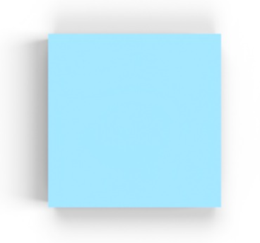
Select the part in the Scene list. In this example a square box is selected and viewed from the top plane. For reference, the box dimensions are .5 m length x .5 m width x .5 m height:
-
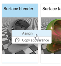
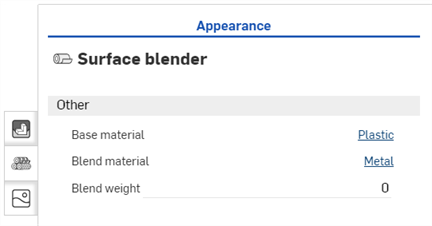
In the Appearance library, search for Surface. Right-click on the Surface blender thumbnail and click Assign (shown in the first image below). The Global submenu in the Appearance panel displays the Surface blender function parameters (second image below):
-
Base material - The appearance on which the blend is based.
-
Blend material - Blend appearance surface properties.
-
Blend weight - Blend weight or mask texture.
-
-
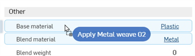
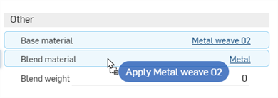
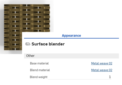
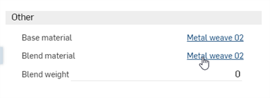
Search for the Metal weave 02 - brass steel Appearance and drag and drop the thumbnail on the Base material parameter (shown in the first image below). Then search for the Metal weave 02 - copper pure Appearance and drag and drop the thumbnail on the Blend material parameter (shown in the second image below). Adjust the Blend weight to 1. This blends the colors between the two appearances (the Base material and the Blend material). The result is shown in the third image below:
-
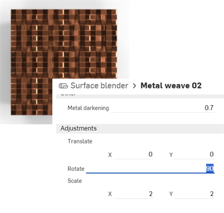
Click on the blend material link to open its parameters in the Appearance panel (shown in the first image below). Rotate the material 90 degrees in the Adjustments submenu. The horizontal pattern is now combined with the newly rotated vertical pattern (shown in the second image below). This better visualizes the blend between the two:
-
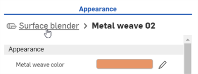
To return to the parent Surface blender layer, click the Surface blender link in the breadcrumb trail at the top of the Appearance panel:
The above procedure works to blend any two surface appearances together. Building on the above procedure, a gradient function is applied to the Surface blender function's Blend weight parameter to blend between the two appearances.
-
Open the 2 Appearances and change their Weave and bar colors to the following: red and green for the Base material, and blue and yellow for the Blend material. This better visualizes the blends in subsequent steps. The result is shown in the second image below:
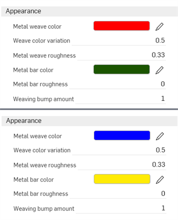
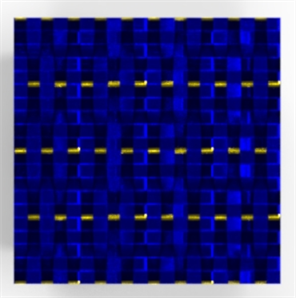
-
Return to the parent Surface blender layer. Search for the Gradient 3-color/position texture function in the Appearance library, and then drag and drop the thumbnail on the Blend weight parameter.
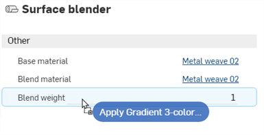
-
The Gradient 3-color/position texture function is now applied to the Blend weight of the Surface blender function's parameter. The gradient is used as a mask between the Base material red and green colors (starting on the left) and the Blend material's blue and yellow colors (ending on the right). Where the gradient is black, the Base material shows through. Where the gradient is white, the Blend material shows through.
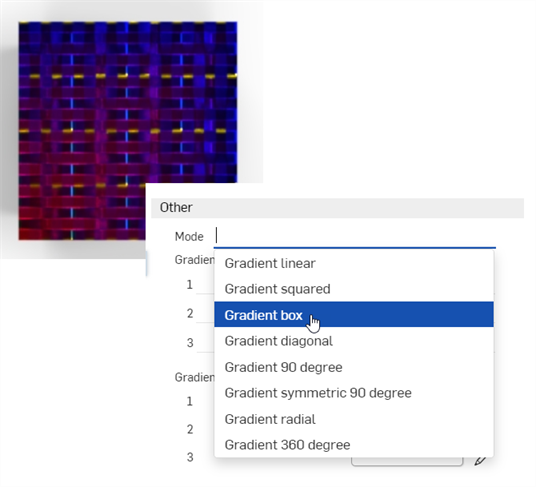
Altering the Gradient parameters produces a variety of gradient results that blend between the two appearances. For example, the image below displays the Mode: Gradient box option (shown in the second image below):
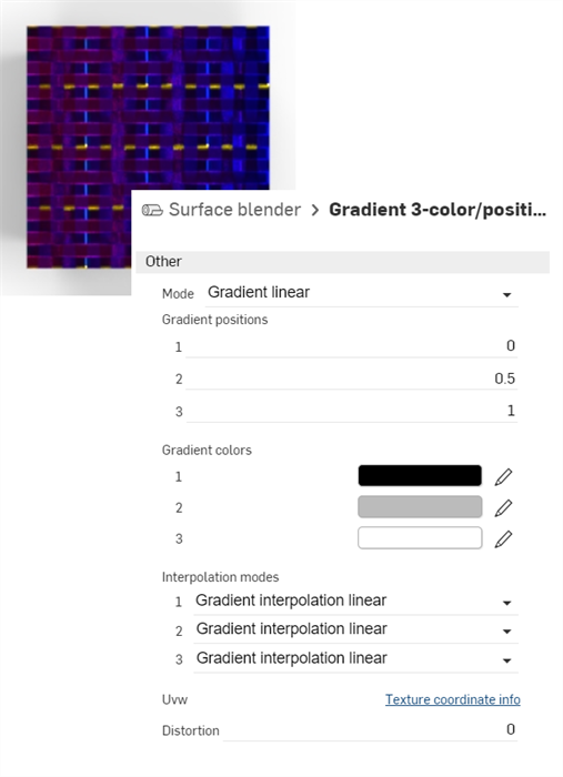
Notes
-
To blend between two colors, use the Blend colors function and apply it wherever a color parameter is available in the Appearance or Selection panel. Using the blend colors function opens access to layer blending modes that are found in applications like Adobe Photoshop and GIMP (darken, screen, multiply, overlay, and others).
-
To blend between two bump textures, use the Blend normals function and apply it wherever the Bumps parameter is available in the Appearance or Selection panel.
-
Instead of the Gradient 3-color/position texture function, use any other texture functions, such as the Checker pattern or Bump map — Perlin noise texture to blend between the two appearances.
-
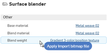
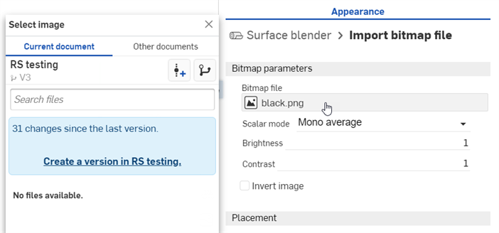
Add a custom texture to blend between the two appearances. Drag and drop the Import bitmap file function on the Blend weight parameter (shown in the first image below), and then Click the Bitmap file to open the Select image dialog, where you can load the custom texture (shown in the second image below):
For a tech tip on blends, see Using textures and blends in Render Studio.
Example 4: Add Volume and Volume coefficient
This procedure explains how to add a specific volume and the Volume coefficient function to a part in the scene. Volume is added as an appearance to the part, while the volume coefficient is a function added to the Absorption coefficient parameter of the appearance.
For this example, a light-emitting ship object is placed in an underwater scene where the water acts as the volume.
-
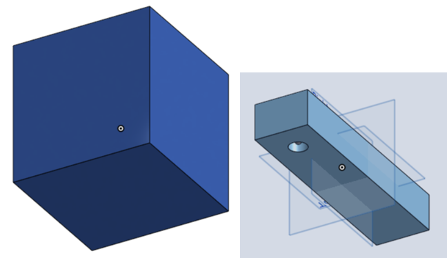
To add volume, the scene must be encompassed by the volume itself. Model a part that surrounds the ship object on all sides, and is large enough to provide sufficient space.
For reference, the surrounding box in this example is 5 m cubed. The rectangular "ship" is 0.6 m length by 0.075 m wide by 0.05 m height. A hole is placed at the front bottom of the rectangle with a diameter of 0.025 and is 0.03 m deep so it does not protrude all the way through the rectangle. Finally, a sphere with a radius of 0.004 m is created inside the hole, which is used as a light source. Each entity (part) is referenced as volume, ship, and light source below.
-
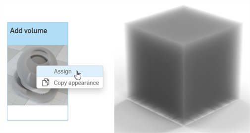
In the Scene list, select the volume part. Search for volume in the Appearances library, right-click on the Add volume thumbnail and select Assign from the context menu. This results in a thick volumetric appearance applied to the surrounding part:
-
Base material - The material onto which the volume is applied. Default is transparent.
-
Absorption coefficient - The probability density (per meter in world space) of light being absorbed by the participating medium. Default is white (R: 255; G: 255; B: 255). A higher absorption value makes the medium darker, due to more of the light being absorbed as it passes through the medium.
-
Scattering coefficient - The probability density (per meter in world space) of light being scattered from its current direction. The default is white (R: 255; G: 255; B: 255). A higher scattering value distributes more of the light throughout the medium.
-
Directional bias - Influence of light direction on scattering. A value of 0 specifies isotropic scattering, 1 forward scattering, and −1 back scattering. The default is 0.
-
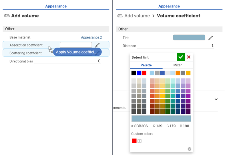
In the Appearances Library > Appearance functions folder, locate, and then drag and drop the Volume coefficient function on top of the Absorption coefficient parameter in the Appearance panel (shown below left). Then adjust the Tint parameter to R: 139; G: 179; B: 198 (shown below right). This creates a volume of water that contains the ship.
-
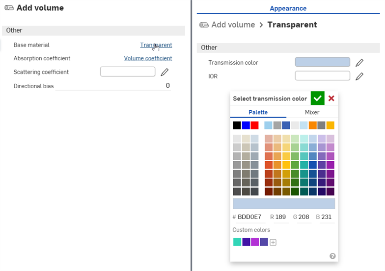
Click the Transparent link next to the Base Material parameter, and adjust the Transmission color to R: 189; G: 208; B: 231, as shown below:
-
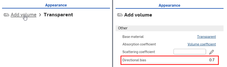
At the top of the Appearance panel, click the Add volume link to return to the volume parameters. Set the Directional bias to 0.7. This lightens the scene, so the ship is visible inside the water:
-
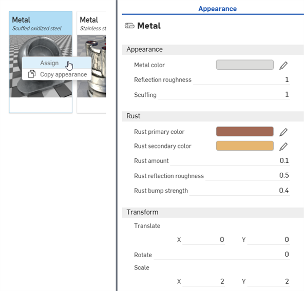
In the Scene list, deselect the volume part and select the ship part. Locate the Metal — Scuffed oxidized steel Appearance in the Appearance library, right-click on the thumbnail and select Assign from the context menu (shown below left). In the Appearance panel, adjust the following parameters: Scale: X: 2 by Y: 2; Rust bump strength: 0.4; Rust amount: 0.1; Rust reflection roughness: 0.5; Reflection roughness: 1:
-
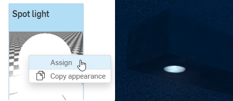
In the Scene list, deselect the ship part and select the light part. Locate the Spot light Appearance in the Appearance library, right-click on the thumbnail and select Assign from the context menu (shown below left). Zoom into the ship to view it from the bottom up. The light is illuminated but is very faint (shown below right):
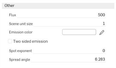
Spot light parameters are:
-
Emission color - Light color. This is rescaled such that it does not influence the luminous flux. The default is white (R: 255; G: 255; B: 255).
-
Flux - The total luminous flux (in lumen) the light emits. The default value is 500. It is generally required to increase this value, depending on the scene.
-
Scene unit size - Convert m to scene unit. For example, if 1 in the scene is one foot (US customary units), then the scene unit size is 0.30481. The default value is 1.
-
Spot exponent - The higher the exponent, the more focused the emission. The default value is 0.
-
Spread angle - Spread angle in RAD. Hard limit for the spot spread. The default value is 6.283.
-
Two sided emission - If enabled, emission occurs on the front and backside of the geometry. The default is disabled.
-
-
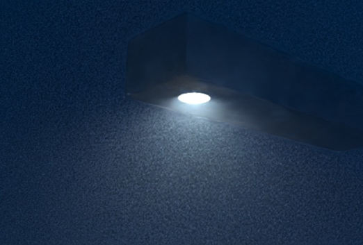
Set the Flux to 20000 and Scene unit size to 0.8. The light now emits a higher intensity light, and is diffuse and unfocused:
-
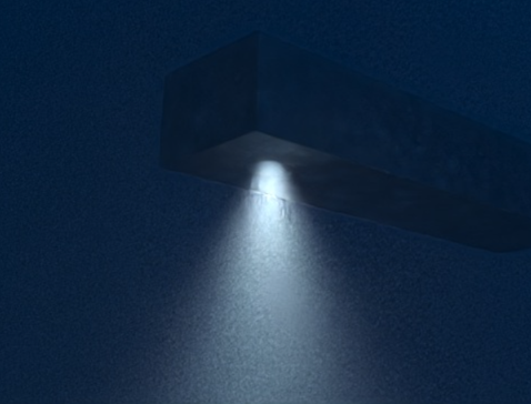
To focus the light to a narrower beam, set the Spot exponent to 15 and Spread angle to 2.5:
-
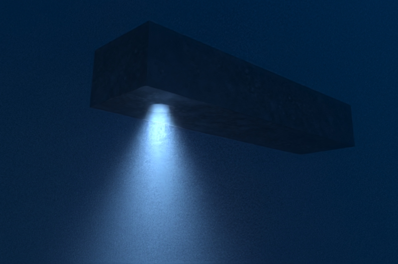
To have the light color blend in with the water, alter the Emission color to R: 157; G: 189; B: 226. Bear in mind that any of these parameters can be adjusted to different specifications. This is one variation on the scene render:
The following outlines the Add volume Appearance panel parameters: