Light Emission

Only available for
Available in: Render Studio
There are several appearances devoted to adding and emitting light from a part, surface, or face in a scene. Which light appearance is used depends on the light source and how the scene in question should be lighted.
 Light emission appearances table
| Light Appearance Name | Description |
| Add emission | Adds emission to a material. See Add a light using the Add emission Appearance for more information. |
|
Add thermal emission |
Adds emission to a material, Color is based on a "color temperature". See Add a thermal emission Appearance for more information. |
| Light source emitter — 1900k candle | AEC - Lights - Candle 1900k Emitter. See Additional light examples for more information. |
| Light source emitter — 7000k cool white emitter | AEC - Lights - Cool White 7000k Emitter. See Additional light examples for more information. |
| Diffuse area light | Material for an area light with a diffuse emission everywhere. See Additional light examples for more information. |
| Display screen | Design - Lights - Display Screen (Illuminated screen for displays). See Display screen for more information. |
| Light source emitter — 5000k fluorescent | AEC - Lights - Fluorescent 5000k Emitter. See Additional light examples for more information. |
| Light source emitter — 3000k halogen | AEC - Lights - Halogen 3000k Emitter. See Additional light examples for more information. |
| IES light | 2 Appearances: (1) Material for a light with Ies defined distribution characteristics and (2) IES profile driven light material, scaling the original data to yield the specified flux. See Add a custom IES light profile for more information. |
| Light source emitter — 4000k natural white | AEC - Lights - Natural White 4000k Emitter. See Additional light examples for more information. |
| Photometric light | Material for a light source driven by IES photometric profile. Note that for profiles using absolute measurements (e.g., those for LED) the multiplier argument should be set to 1.0. See Additional light examples for more information. |
| Spot light | 3 Appearances: (1) Material for a light with a shaped emission characteristic, (2) Spot light material with global (object orientation aligned) distribution, and (3) glTF 2.0 spot light source. See Add a spot light and reflective surface and Add Volume and Volume coefficient for two spot light examples. |
| Light source emitter — 2700k warm white | AEC - Lights - Warm White 2700k Emitter. See Additional light examples for more information. |
In addition to the above light appearances, add a bloom filter via the Scene panel. See also Light (Render Studio Advanced).
Adding a light using the Add emission Appearance
This is a simple way to add a light emission to any part in the scene:
-
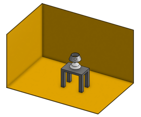
In a Part Studio or Assembly, create a part used as a light source and add some walls around the part. In this example, a light bulb is modeled, with some side walls and a floor:
-
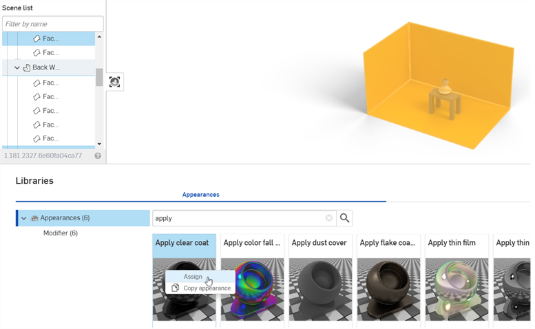
Select the walls in the Scene list.
-
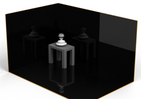
In the Appearance library, search for apply. Right-click on the Apply clear coat Appearance and click Assign from the context menu. This adds reflective surfaces off which the light emission reflects:
-
In the Scene list or graphics area, select the bulb's glass cover.
-
In the Appearance library, locate the Thin glass Appearance. Right-click on its thumbnail and click Assign from the context menu.
In the example below, a metal Appearance is assigned to the screw base, and a copper Appearance to the bottom bulb connector. Finally, the lamp, lamp shade, and table are removed, to better showcase the bulb's emission.
-
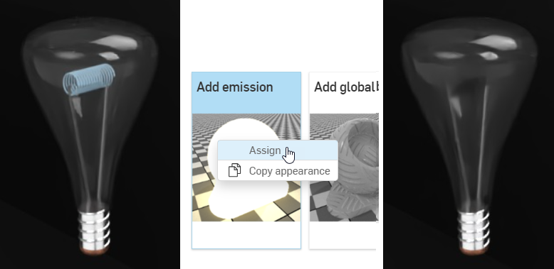
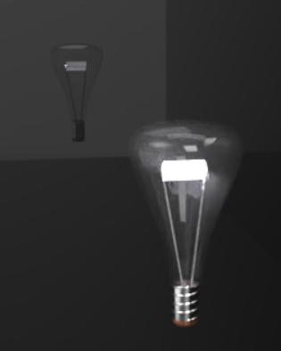
In the Scene list, select the part used for the filament inside the bulb (shown in the left image below).
-
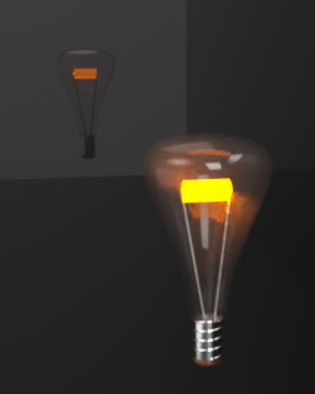
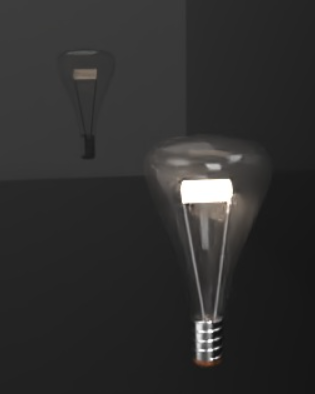
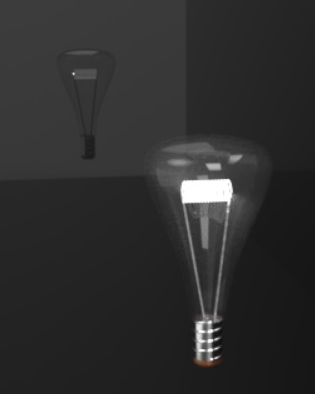
In the Appearances library, locate the Add emission Appearance. Right-click on its thumbnail and click Assign from the context menu (shown in the middle image below). The filament appears dark at first (shown in the right image below):
Appearance options are:
-
Base material - The material to which the emission is added. The default is diffuse.
-
Intensity - The brightness of the light source. The default value is 1000.
-
Color - The light emission color. The default is white (R: 255; G: 255; B: 255).
-
Unit for emission - The physical unit of "Intensity". The default is Lumen m2. Other options are Lumen, Candela, and Nit.
-
Unit scale - The modeling unit to meter conversion factor. The default value is 100.
-
-
In the Appearance panel, adjust the emission Intensity upward. Keep in mind this value depends largely on the scene dimensions. For reference, the dimensions of the room created below are 2.43 m length by .97 m wide by .84 m height. The Intensity value is set to 10000000. This creates an emissive white light:
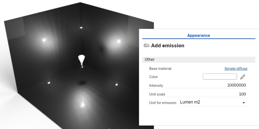
-
Adjust the color to control the warmth or coolness of the light emission. The following example displays how the light emission changes when a new color is selected:
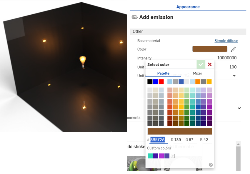
-
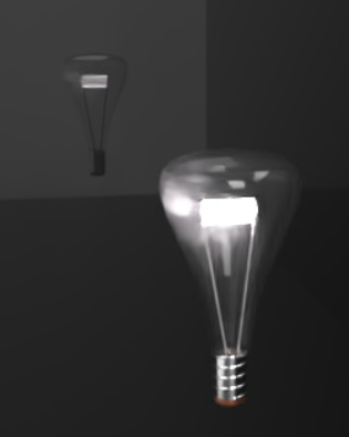
Zoom into the bulb, decrease the intensity, and change the color to blue to create the emission shown below:
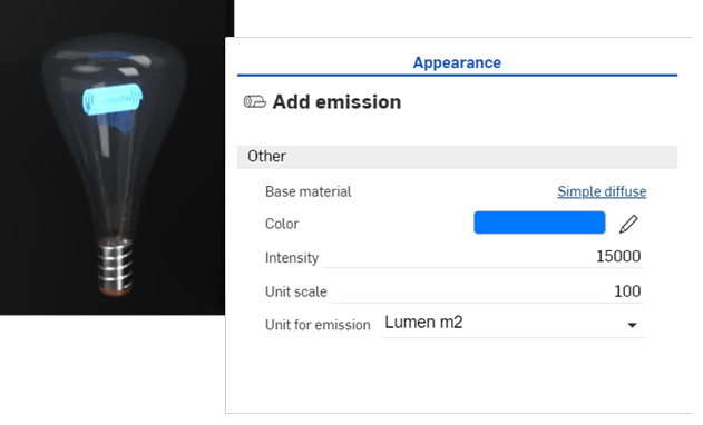
-
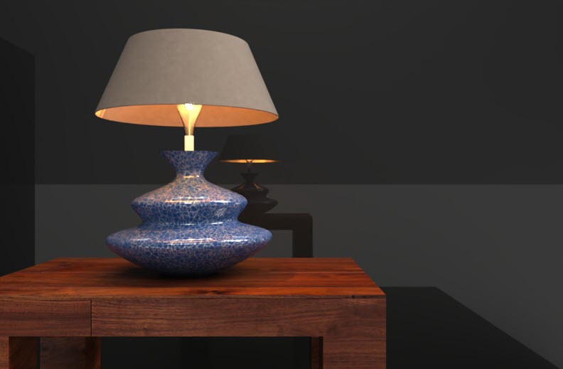
The final example shows how the light bulb is used in a completed scene, with the addition of a lamp and table. Note how the shade over the bulb redirects the light emission upward and downward, and dulls the emissions where the shade is set between the light source and the walls:
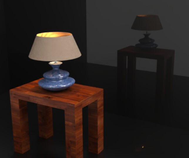
Adding a thermal emission Appearance
Similar to the Add emission appearance, the Add thermal emission appearance adds light to a modeled part, surface, or face. However, the light source is meant to act as a source of thermal heat. The Color parameter is replaced by a Temperature parameter, which is adjusted to define the type of heat source.
-
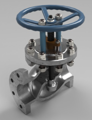
Once the part is modeled, create a scene from the Part Studio or Assembly. The example used here is a Valve assembly:
-
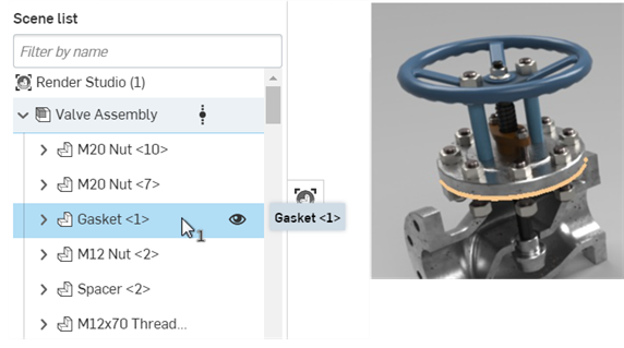
Select the part in the Scene list or graphics area. This is the part used as the thermal emission origin. In the example below, the gasket is used as the emission source:
-
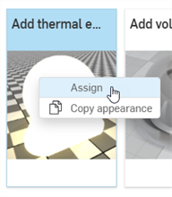
In the Appearances library, locate the Add thermal emission Appearance. Right-click on its thumbnail and click Assign from the context menu:
-
In the Appearance panel, adjust the Intensity upward. For this scene, the Intensity is set to 10000000. Then set the Temperature to 2000. This creates an orange-colored thermal emission:
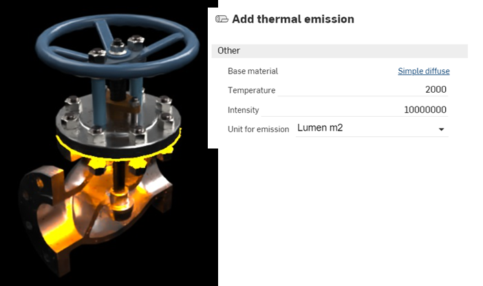
-
Setting the Temperature value to 65000 changes the emission color to blue, which is used, for example, to indicate heat from a hydrocarbon source, such as butane or propane gas:
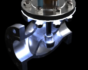
As a general guideline, values from 0 to 3500 are in the red-orange-yellow range, while numbers from 10000 upward are in the blue range. The default value of 6500 emits a white color.
Adding a custom IES light profile
IES light profiles describe the distribution of light from a lamp. This data is provided by many manufacturers so that designers can realistically render light within a room.
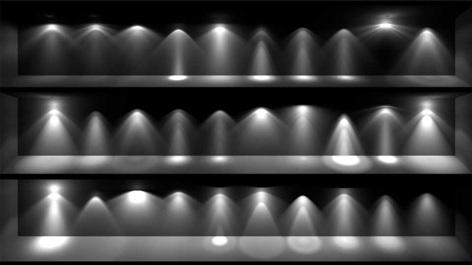
An example of several IES profiles.
Render Studio provides the ability to add an IES light profile to a light source.
-
Select the part or face in the Scene list or graphics area.
-
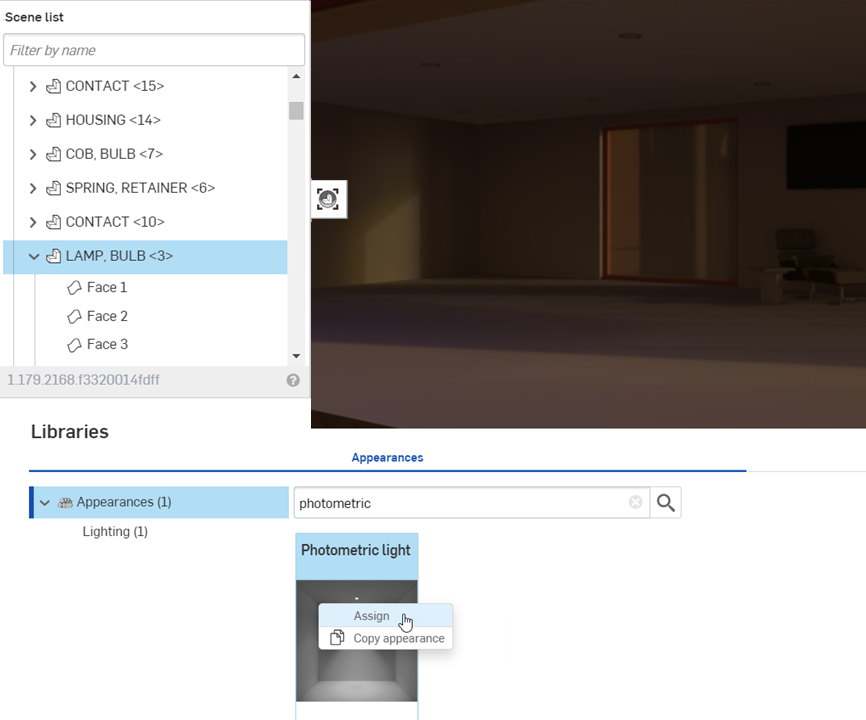
Search the Appearances library for Photometric. Right-click on the Photometric light thumbnail, and click Assign from the context menu. The example below is a living room with a very dark environment:
-
In the Appearance panel > Distribution submenu, click the IES file (downlight.ies). This opens the Select light profile dialog.
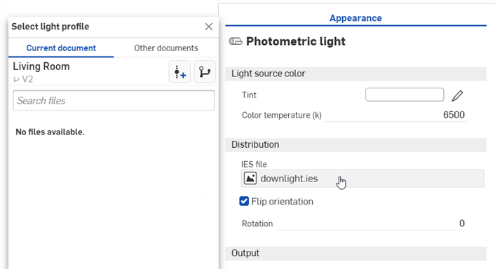
-
Do one of the following:
-
Select an IES file from the Current document
-
Click Other documents to locate an IES file in another Onshape document
-
Click the Import link at the bottom of the dialog to locate an IES file from your computer. When selected, click the Open button:
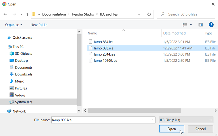
Once the notification indicates the upload is complete, you will not yet see the image in the Select image dialog. This is because the Render Studio scene is a snapshot of the part, Part Studio, or Assembly at the time of import, and this image is brought into the Onshape document post-import. A new version is now required, in order to update the scene. Click the Create a version in [Document name] link in the Select image dialog:
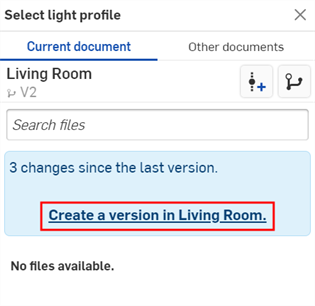
The Create version dialog opens. Enter the version information and click the Create button.
-
-
Once the new version is created, the IES file is located in the Select light profile. Click it to select it:
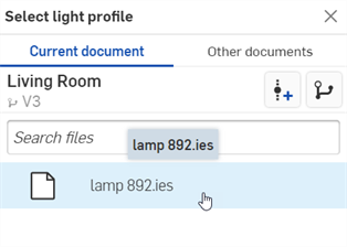
-
Once selected, the file is loaded into the IES file field:
-
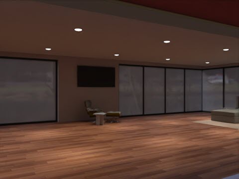
Edit the parameters in the Appearance panel submenus. For example, alter the Tint to change the light color, and increase the intensity of the light by adjusting the Lumens or multiplier. In the examples below, the IES profiles are applied to the recessed lights in the living room ceiling:
If you don't see the Create version link in the Select light profile dialog, click the Create version button ( ) on the Document panel to open the Create version dialog. Create the new version. Close and reopen the Select light profile dialog. The imported image should now be available.
See Importing files for more information about uploading files.
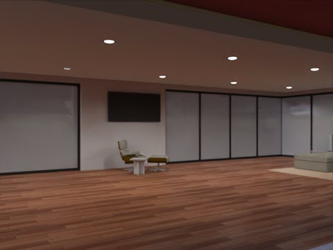
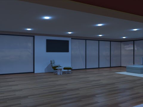
Below are two variations on the lighting. The first image uses an IES profile with a wider emission spread than the example above, while the second image uses an IES profile that emits a halo surrounding the bulbs. The Emission color is set to blue:
For a collection of free IES profiles, visit https://ieslibrary.com/en/home
Adding a Display screen Appearance
The Display screen is a very specific type of appearance used to replicate an image on a television, computer, or other digital screen. Options are:
-
Image - Opens the Select image dialog, where you can locate an image to be mapped onto the display.
-
Repeat image - If enabled, the image repeats across the UV coordinates. If disabled, a single instance of the image displays across the UV coordinates. The default is enabled.
-
Intensity - The display emission intensity. The default value is 40. Note that when applying this appearance, the light source will most likely be black. Increasing the intensity to a higher value should yield a sufficient intensity to view the emission. This depends on scene size.
-
Screen roughness - Higher roughness values lead to bigger highlights and blurrier reflections. The default value is 0.2.
-
Translate - Controls the position of the image along the x and y axes.
-
Rotate - The Rotation angle of the image in degrees.
-
Scale - Scales the image size along the x and y axes. Larger numbers increase the size. Smaller numbers decrease the size.
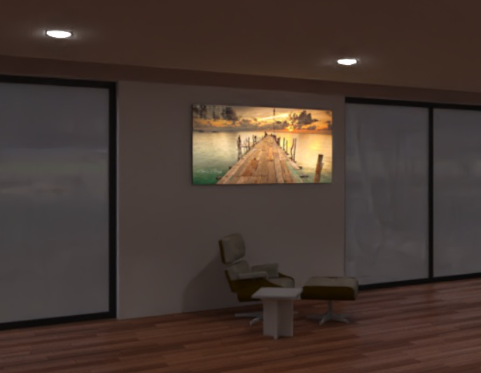
Display screen light example (applied to the front face of the wall screen)
Intensity: 200000
Additional light examples
The following lights all use the same base Light source emitter parameters. Only the Color temperature value varies:
-
Color temperature - Color temperature, in Kelvin.
-
Lumens (flux) - The luminous flux, in lumens, the light emits. The default value is 1000.
-
Two-sided emission - If true, emission happens on the front and back sides of the geometry. The default is disabled.
|
1900k candle
|
7000k cool white
|
5000k fluorescent
|
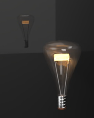
3000k halogen
|
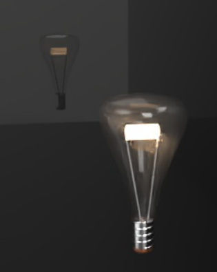
4000k natural white
|
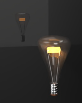
2700k warm white
|
The following are Diffuse area light options:
Diffuse area light:
-
Flux - The luminous flux (in lumen) the light emits in total. The default value is 500.
-
Scene unit size - Convert meter to scene unit. Examples: 1 in the scene is one foot: Scene unit size = 0.30481.0 in the scene is a centimeter: Scene unit size = 0.01.
-
Emission color - The color of the light. This is rescaled such that it does not influence the luminous flux. The default value is white (R: 255; G: 255; B: 255).
-
Two-sided emission - If true, emission happens on the front and back sides of the geometry. The default is disabled.
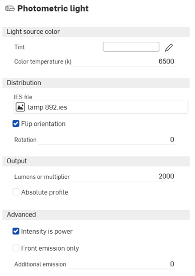
The following are Photometric light options:
Photometric light:
-
Tint - Additional tint color for emitted light (for example, for simulating gels). The default value is white (R: 255; G: 255; B: 255).
-
Color temperature - Color temperature, in Kelvin. The default value is 6500.
-
IES file - The IES light profile used to specify the light distribution. See Add a custom IES light profile for more information.
-
Flip orientation - Reorients the light profiles up vector, which is oriented towards the y direction by default, towards the z direction. The default is enabled.
-
Rotation - Rotates the distribution around the light profiles up vector. The default is disabled.
-
Lumens or multiplier - Light intensity. If Absolute Profile is disabled, then this is the lumen output of the light. If enabled, then this is a multiplier applied to the native light profile intensity. The default value is 2000.
-
Absolute profile - Controls whether the intensity is lumen output of the light (disabled) or multiplies the native light output (enabled). The default is disabled.
-
Intensity is power - If enabled, the intensity is interpreted as power. Consequently, the output is divided by the area of the light source to yield radiance. That means the scene brightness stays about the same if the light source surface area is enlarged. The default is enabled.
-
Front emission only - Disables emission on the backface of an area light. This is required for cylindrical lights to prevent illumination from leaking out the open cylinder caps. Technically, this should also be set for spherical lights, even though these lights will not leak. The default is disabled.
-
Additional emission - Used to add a basic Lambertian emission to the light. Useful for avoiding dark light sources when viewed directly. The default value is 0.
Photometric light example
Lumens or multiplier: 20000; Flip orientation: disabled