操作匯入的 CAD
![]()
![]()
![]()
在 Onshape 中從頭開始設計並不是建立或優化您 CAD 模型的唯一方式。如果您在另一系統中有已存的 CAD 資料,可以將該資料匯入至 Onshape 中並繼續設計的工作。
Onshape 接受許多來自其他系統的資料,最受歡迎與轉譯效果佳的是 Parasolid 檔案。關於 Onshape 可接受的檔案類型與匯入資料方法的詳細資訊,請參考支援的檔案格式與匯入檔案。
這個主題說明在您將現有的 CAD 資料匯入至 Onshape 之後,如何繼續操作以及可使用的工具。
Onshape 工具
由於系統之間的差異,匯入至 Onshape 的資料可能會有轉譯錯誤,或沒有參數式的歷程記錄,或可能匯入為的一連串的曲面或零件而非一個實體或凝聚結合的本體。雖然在您匯入時對如何處理資料有一些選項,可能仍有一些無法操控的狀況。此時,Onshape 提供的工具可幫助您處理匯入的資料,並可繼續設計、共享與發行對所匯入資料的設計。
提供的工具可幫助您操控匯入的 CAD 資料,在這個說明主題中涵蓋包括下列的工具:
Onshape 讓您能夠匯入下列小平面檔案格式以供視覺檢視與參考。可以將網格點用做頂點來建立平面。
-
Parasolid 網格
-
STL
-
OBJ
-
GLTF
-
3MF
會將網格匯入至 Onshape Part Studio 中並顯示於網格之下的零件清單中 (於曲面之下)。
您可以檢視與參考網格,但無法編輯。
網格頂點的選擇不是參數式的,且與網格頂點無關。相反地系統會記錄下其位置。因此,對匯入網格所做的編輯 (例如,變換) 並不會更新其位置。
您可在匯入的過程中變更網格的單位,請在索引標籤功能表中的下拉清單內選擇一個單位,如下方第二個圖示所示:
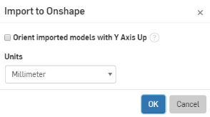
上圖是在匯入的過程中
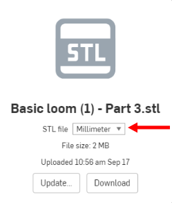
上圖是在匯入的分頁之中
可執行的操作
一旦將網格匯入至 Onshape Part Studio 之後,您可以:
- 使用網格點來建立三點平面
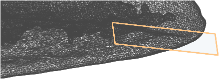
- 測量表面積、網格點間的距離以及實體網格的質量屬性


- 將網格投影到草圖上 (藉由使用工具)
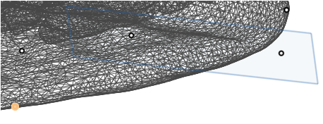
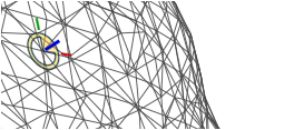
- 在網格點上建立結合連接器
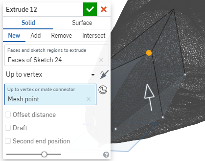
- 為「成形至一頂點」的操作參考網格點 (在擠出當中)
關於在混合式模型建構中操作網格的詳細資訊,請參考混合式模型建構。
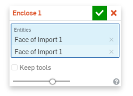
在匯入時如果零件或曲面是斷裂的,或者是您要將個別的本體視為一個結合凝聚的單位,可以考慮建立一封閉或開放的複合零件 (一個會消耗圖元,另一個則不會)。
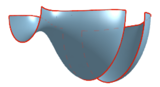
例如,如果您的設計在匯入的過程中斷裂,如同下方範例中所示,設計其中的一個部分被渲染為多個曲面,您可以選擇斷裂的圖元然後將其合併為一個複合零件:
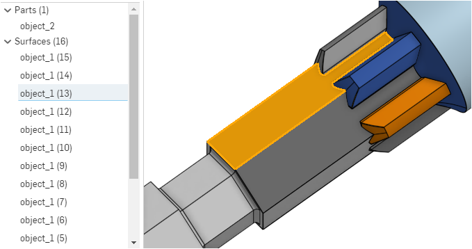
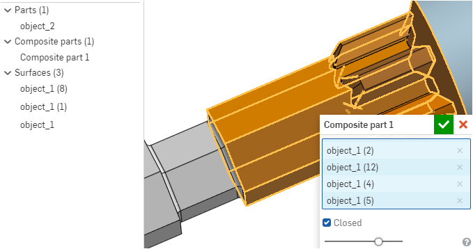
選取的曲面 "object_1(13)" 會在模型中交叉強調顯示,但假設您要全部的曲面都在一個零件中,您可以選擇這些曲面然後建立一個複合零件,如下所示:
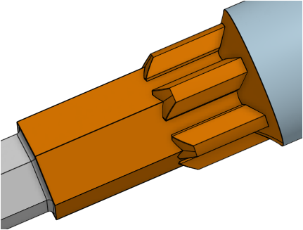
在接受特徵之後零件看起來的樣子:
匯入的幾何並未帶有參數式的歷程記錄,因此有時您可能需要使用 Onshape 的直接編輯工具來繼續建構匯入模型的設計。
例如,在您匯入零件之後,鑽孔可能是在錯誤的位置上。您可以使用直接編輯工具來移除原始的鑽孔,然後在模型的適當位置上建立新的鑽孔。
另一個範例是,當面遺失或有錯誤時,需要修改匯入的幾何,或是您必須刪除一個面然後再重新產生它。在下方的範例中,需要重新調整蓋子上方旋鈕的形狀,因此需要使用「刪除面」工具:
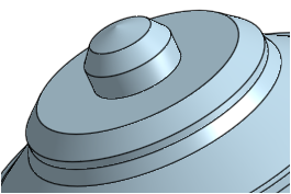
上圖是附有旋鈕的匯入蓋子
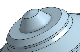
上圖選取了要移除的面
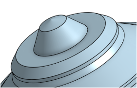
上圖是改用新面所產生的蓋子
在匯入零件之後,在「特徵」清單中會顯示「匯入」特徵 ( ![]() ) (下方的「Import 1」):
) (下方的「Import 1」):
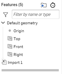
編輯匯入後的特徵:
-
連按兩下「匯入」特徵,或在「匯入」特徵上按右鍵然後從環境選單中選擇 [編輯]。
-
「匯入」對話方塊開啟:
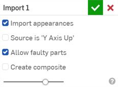
-
調整下列的設定。可以隨時啟用/停用這些設定。
-
匯入外觀 - 核取以匯入原始的外觀。可以按一下「外觀面板」圖示 (
 ) 來開啟在右側的「外觀面板」以存取這些外觀。取消核取來從匯入的零件中移除所有的外觀。詳細資訊請參考自訂零件、面、特徵、與草圖:外觀。
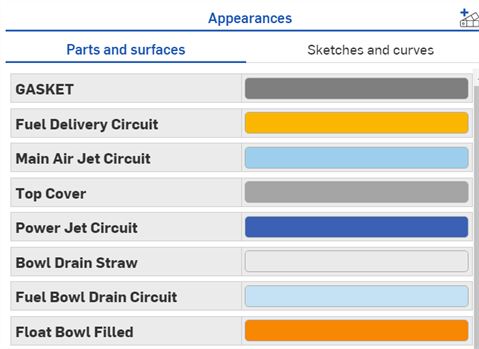
-
來源是 'Y 軸朝上' - Onshape 的朝上軸是 Z 軸。在取消核取時,系統會以 Z 軸朝上來匯入模型。對於來自朝上軸是 Y 軸系統的 CAD 檔案,核取這個方塊可以 Y 軸朝上來匯入模型。除了 Autodesk (.ipt) 與 CATIA (.catpart) 以外,Onshape 支援所有其他系統/檔案的 Y 軸朝上選項。
-
允許有問題的零件 - 核取來允許有問題的零件。取消核取來禁止匯入零件中有問題的零件。有問題的零件是那些有拓樸問題的零件。會在「零件」清單中以紅色顯示有問題零件的零件或曲面。
-
建立複合 - 如果核取,在匯入由多個非實體本體組成的中性 CAD 檔案 (例如,.step 或 .x_t) 時,會手動建立複合零件。不論零件是否屬於相同的本體,在已匯入 Part Studio 中的所有零件會變為一個單一封閉複合零件。
-
在匯入零件之後,如果零件在來源檔案中變更,您可以更新零件。
當選取「分成多個文件」選項時,將無法更新最上層的組合件檔案。詳細資訊請參考匯入檔案。
更新先前匯入的零件:
- 再次從其他 CAD 系統中匯出零件 (假設這個零件自上次匯出後有所變更)。
- 在已匯出零件所在的處的先前匯入文件內,執行下列操作之一:
- 開啟零件所在處的 Part Studio,在「特徵」清單中的匯入項目上按右鍵,然後選擇更新。
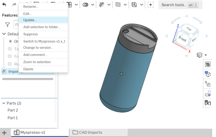
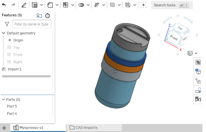
選擇匯出的檔案然後按一下 [開啟]。匯入的功能會更新零件。
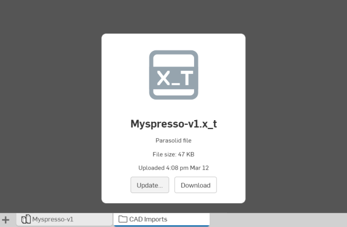
- 按一下 CAD 匯入資料夾然後選擇匯入檔案的分頁。按一下 更新 (如下圖所示),選擇匯出的檔案再按一下開啟。系統會顯示新的檔案名稱,並在 Part Studio 中更新零件。
如果尚未在 Onshape release 1.93 後更新文件,則這個 [更新] 的按鈕不會升級所匯入的特徵,而是會建立一個包含新/經升級零件的新 Part Studio。 如果已在 Onshape release 1.93 之後的版本中升級文件,則當點按 [更新] 按鈕時,會以新檔案更新所匯入的 blob,且經更新的幾何會傳入至匯入的特徵中。
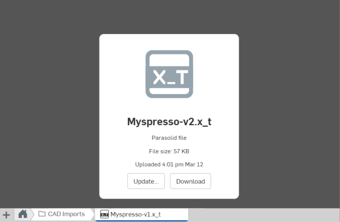
在兩種狀況中,都會更新包含匯入特徵的 Part Studio。
- 開啟零件所在處的 Part Studio,在「特徵」清單中的匯入項目上按右鍵,然後選擇更新。
經更新的項目
當更新零件時,在來源系統中的所有特徵與對零件的變更都會在目標 Part Studio 中被更新。如果已在目標 Part Studio 中修改了零件 (例如套用特徵),會在可能的情況下再次套用這些特徵到更新的零件中。
例如,如果在目標 Part Studio 中已將圓角套用至零件上,會將圓角重新套用至更新零件的可能處。對來源零件所做的模型設計變更可能會導致在目標 Part Studio 套用特徵的重新計算失敗。系統會在特徵清單中以錯誤的狀態顯示這些特徵。
僅會更新 Part Studio。目前不支援更新組合件。在執行更新之後,組合件 (與所有實例) 仍維持原始匯入時的狀態。
有時候當您匯入一個專案到 Onshape 中時,常用的零組件可能會變得重複。由於並不希望有重複的零組件存在,在 Onshape 中您可以對一個零組件改用多個參考來取代。
基於組織管理的考量,最好是將共用零組件移動到其自己的文件之中,這樣所有使用者可輕鬆地找出零組件而不影響專案的進行。若要將一個零組件從一個文件移動到另一個文件:
- 在 Part Studio 的零件清單中選擇零組件的名稱。
- 按右鍵並選擇 [匯出]。
- 在文件頁面上按一下 [建立],然後再點按 [匯入]。
- 匯入您剛才匯出的檔案,這樣會建立一個新文件。
- 在原始的文件中,於原始的 Part Studio 內找出零件。
- 從 Part Studio 中刪除零件。
注意到在這個文件中,所有對該零件 (在組合件中) 的參考都會斷開且以紅色顯示。
- 在參考該零件的每個組合件中,於實例清單中選擇對零件的每個參考,按右鍵並選擇 [取代實例]。
- 在「取代實例」對話方塊中,導覽至「本人所建立」的文件區域,然後選取包含共用零組件的新來源文件。
- 現在會將零組件插入至組合件中被參考之處,但旁邊會有一個連結的圖示。連結的圖示表示實例是參考另一個文件中的零組件。
這個工作流程的好處是您現在可以建立一個零組件的多個實例。如果您要變更零組件,可以在來源文件中執行,然後您可以決定是否要與何時要在其他文件中更新對實例的參考。這樣可以免除不需要的重新插入與跟其他多個零組件的結合,同時可幫助您輕鬆地使用最新的零組件。
有關更深入說明的範例,請參考這個 Onshape Tech Tip。
當刪除匯入的檔案時,您會看告一個警告說明刪除會影響的 Part Studio 為何:

![檢視工具功能表選項中以紅色輪廓線框出 [隱藏強調顯示的邊界]](Resources/Images/feature-tools/highlight-boundaryedges-01.png)
