 受限曲面
受限曲面
![]()
![]()
![]()
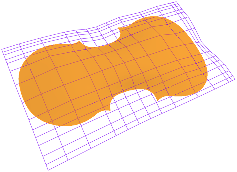
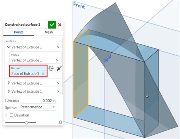
根据指定公差范围内的点或网格数据创建曲面。显示偏差并优化性能或平滑度。
与编织布类似,每个曲面大致都是矩形。曲面有三个方向:U、V 和法向。边界曲面剖面 U 和 V 分别代表曲面的 X 和 Y 方向。
- 单击“受限”曲面图标 (
 )。
)。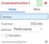
- 选择通过点或网格数据定义曲面。
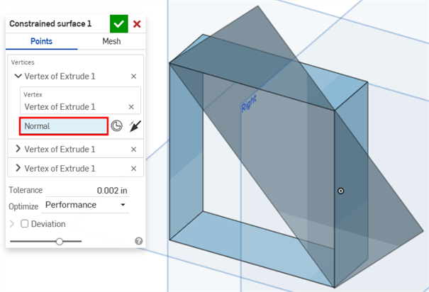
- 点 - 选择顶点来定义曲面。曲面是垂直于所选顶点创建的。要更改曲面的方向,请在对话框中单击顶点以显示其他选项:
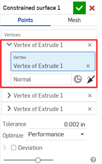
- 单击“垂直”输入框将其选中,然后从模型中选择创建曲面的方向。
- 单击“嵌合连接器”按钮选择嵌合连接器。
- 单击“垂直反转”按钮切换方向。
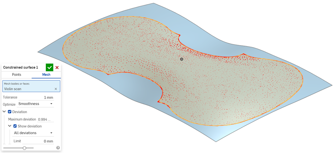
- 网格 - 选择网格实体或面来定义曲面。
- 点 - 选择顶点来定义曲面。曲面是垂直于所选顶点创建的。要更改曲面的方向,请在对话框中单击顶点以显示其他选项:
- 设置创建曲面时允许的“公差”。公差越大,生成的曲面越简单和越大。
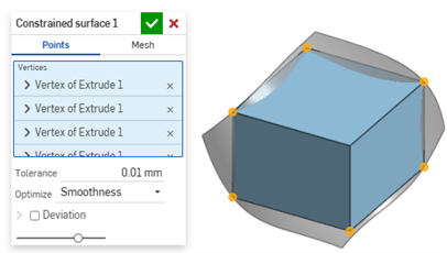
- 单击“优化”下拉列表,然后选择优化性能或平滑度。
- 性能 - 性能越快产生的曲面质量可能越低。
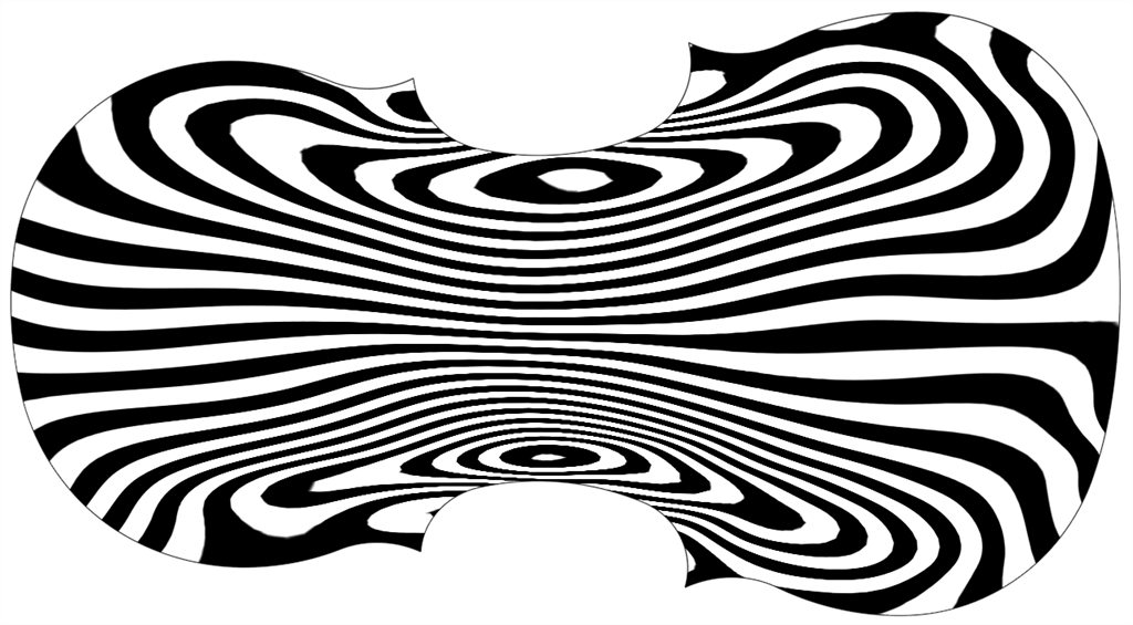
- 平滑度 - 通常以较低的曲率生成质量更高的曲面,但性能较慢且控制点较多。
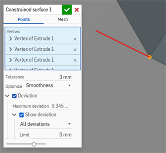
- 单击“偏差”复选框以查看原始点/网格与创建的曲面之间的最大偏差。
- 单击“显示偏差”复选框以显示模型上的“最大偏差”或“所有偏差”。
- 设置显示偏差的“极限”。任何低于输入限值的偏差都不会显示在模型上。
- 单击
 。
。
这列出了曲面特征工具的集合。这不是一份详尽的清单。对曲面建模时可以使用其他特征工具。有关其他信息,请参阅曲面。
-
 加厚 - 增加曲面的深度。通过赋予曲面厚度并将其转换为实体、在现有零件或曲面中添加或移除材料,或者在其路径中与零件相交来创建新零件或修改现有零件。
 -
 闭合 -通过选择空白空间周围的所有边界来创建零件以形成实体。使用任何一组相互相交或在边界处连接的曲面和实体(包括平面和面)来创建体积。通过添加、移除或交叉零件来创建新零件或修改现有零件。
 -
 圆角 - 使尖锐的内部和外部边变圆,并通过选择“边圆角”定义为标准固定半径、或更样式化的圆锥或变量。或者,可选择应用全圆角,以在两条相对边之间创建一个或多个面的无缝融合。
 -
 面混合 - 圆滑化锐化连接或不相连的内部和外部面,以在面之间创建无缝混合,或者分离混合以创建新面,定义半径或恒定宽度。进一步定义混合横截面(滚球或扫掠轮廓)、对称性、控制、修剪、约束和界限。
 -
 删除面 - 从零件中移除几何图元。选择是否修复周围的面(通过延伸面,直到它们相交)、封口空心或保持空心开放。如果没有零件的参数化历史记录(导入的零件常常出现这种情况),此直接编辑工具特别方便。
 -
 移动面 - 平移、旋转或偏移一个或多个选定面。如果没有零件的参数化历史记录(导入的零件常常出现这种情况),此直接编辑工具特别方便。
 -
 替换面 - 修剪面或将面延伸到新曲面。如果没有零件的参数化历史记录(导入的零件常常出现这种情况),此直接编辑工具特别方便。
 -
 偏移曲面 - 通过偏移现有面、曲面或草图面域创建新曲面。将偏移距离设置为 0 可在原位创建一个副本。
 -
 边界曲面 - 创建或添加由其边界轮廓指定的曲面。
 -
 填充 - 通过定义边界创建曲面(或从曲面创建零件),并使用边界条件优化曲面(而非要求使用参考曲面)。
 -
 移动边界 - 移动曲面的边界边以对其进行延伸或修剪。
 -
 直纹曲面 - 从草图区域的现有边或多条边创建新的或额外的直纹曲面。
 -
 相互修剪 - 通过延伸交点来修剪两个相邻的曲面以完成修剪。
 -
受限曲面 - 根据指定公差范围内的点或网格数据创建曲面。显示偏差并优化性能或平滑度。
- 点按“受限曲面”图标 ()。
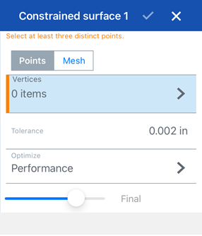
- 选择通过点或网格数据定义曲面。
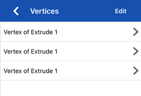
- 点 - 选择顶点来定义曲面。曲面是垂直于所选顶点创建的。要更改曲面的方向,请点击顶点,然后点击顶点(下方的第一张图片)以显示顶点组的其他选项(下方的第二张图片):
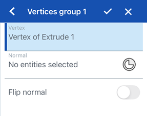
- 轻按“垂直”输入框将其选中,然后从模型中选择创建曲面的方向。
- 轻按“嵌合连接器”按钮选择嵌合连接器。
- 打开“垂直翻转”以切换方向。
- 网格 - 选择网格实体或面来定义曲面。
- 点 - 选择顶点来定义曲面。曲面是垂直于所选顶点创建的。要更改曲面的方向,请点击顶点,然后点击顶点(下方的第一张图片)以显示顶点组的其他选项(下方的第二张图片):
- 设置创建曲面时允许的“公差”。公差越大,生成的曲面越简单和越大。
- 点击“优化”下拉列表,然后选择优化性能或平滑度。
- 性能 - 性能越快产生的曲面质量可能越低。
- 平滑度 - 通常以较低的曲率生成质量更高的曲面,但性能较慢且控制点较多。
- 开启偏差以查看原点/网格与创建的曲面之间的最大偏差。
- 打开“显示偏差”以显示偏差类型。点击,然后选择模型上的最大偏差或所有偏差。
- 设置显示偏差的“极限”。任何低于输入限值的偏差都不会显示在模型上。
- 轻按复选标记。
iOS 和 Android 对受限曲面特征的支持仅限于显示和编辑现有曲面。只能在桌面(浏览器)平台上创建受限曲面。无法在 Android 平台上创建受限曲面。