Creación de un dibujo


Disponible en: dibujo
Cuando crea un dibujo de una pieza, curva o superficie en un Part Studio o Ensamblaje, el dibujo contiene vistas predeterminadas. También puede crear un dibujo vacío mediante el menú  en la esquina inferior izquierda de la ventana y seleccionar Crear dibujo.
 Creación de dibujos con vistas predeterminadas
En la lista piezas de un Part Studio o un ensamblaje:
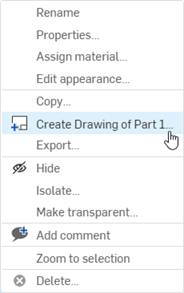
Haga clic con el botón derecho en una pieza, curva o superficie. Seleccione Crear dibujo de <nombre de la pieza, curva o superficie>.
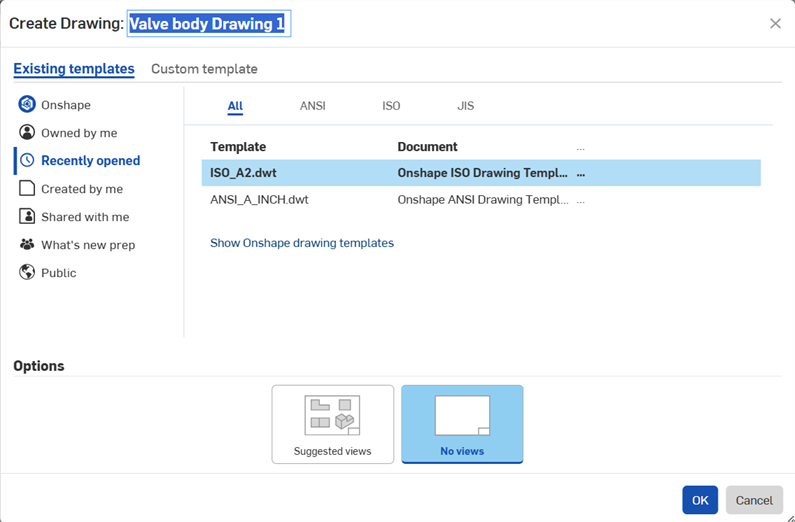
The drawing will populate it's name based on the existing part, curve, or surface name. You can edit the name of the drawing by clicking on the existing name (outlined in red below) at the top of the Create drawing dialog and typing your preferred name:
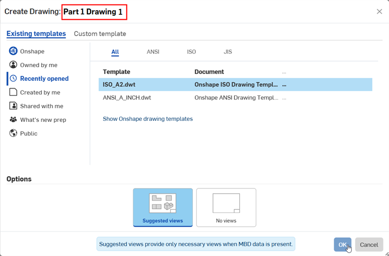
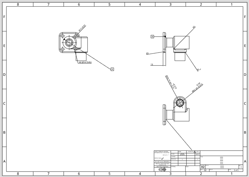
Click Suggested views at the bottom of the dialog and then click OK. Four views of the part are inserted into the drawing:
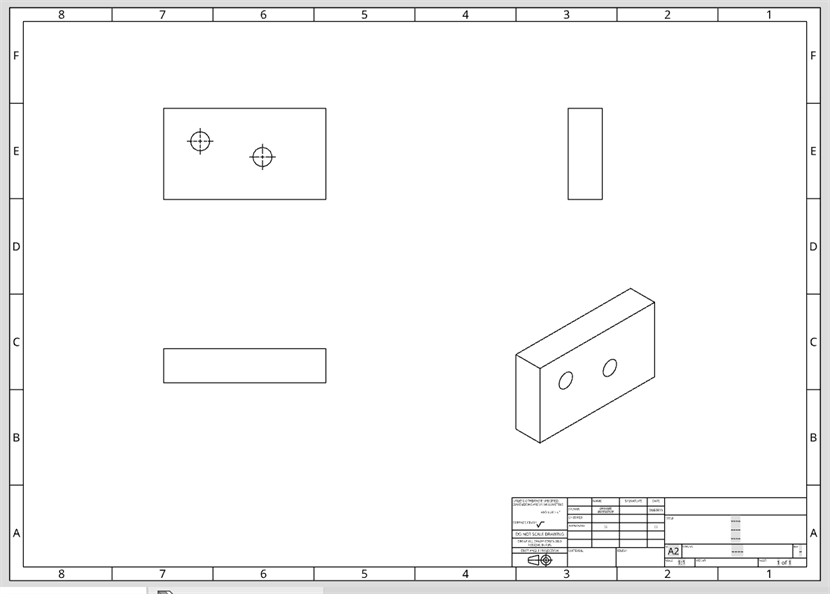
De forma predeterminada, las extensiones de centro de masa de la plantilla están activadas. Para eliminar un centro de masa, haga clic para seleccionarlo y presione la tecla Eliminar. Consulte centros de masa para obtener más información sobre las opciones de edición de centros de masa.
Create drawing from a part with MBD data
En la lista piezas de un Part Studio o un ensamblaje:
-
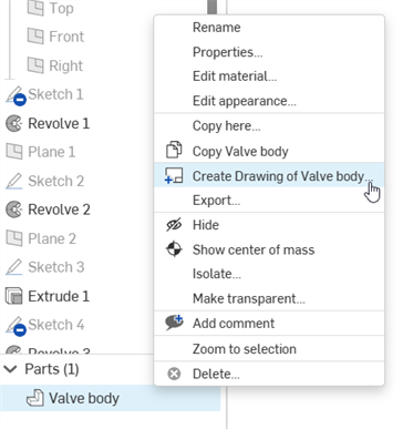
Right click on a part. Select Create drawing of <part>.
-
El dibujo rellenará su nombre basándose en el nombre de la pieza, curva o superficie existentes. Puede editar el nombre del dibujo haciendo clic en el nombre existente (que se muestra resaltado a continuación) en la parte superior del cuadro de diálogo Crear dibujo y escribiendo su nombre preferido:
-
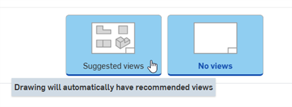
Click Suggested views at the bottom of the dialog and then click OK.
-
Suggested views - Automates the placement of up to 6 orthographic views: front, top, left, back, bottom, right. If there is MBD data present on the front top and left planes. these views are automatically placed in the drawing sheet and the annotations are displayed in the view. If there is MBD data present in the part, but not in the suggested views inserted into the drawing, they are displayed in the MBD Status panel's Datums and Characteristics tables.
-
No views - Opens an empty drawing sheet, where the user can select which views to insert. Once users insert a view, If MBD data is present on the view plane being inserted, this data is displayed in the inserted drawing view. Any missing data is displayed in the MBD status panel's Datums and Characteristics tables automatically.
De forma predeterminada, las extensiones de centro de masa de la plantilla están activadas. Para eliminar un centro de masa, haga clic para seleccionarlo y presione la tecla Eliminar. Consulte centros de masa para obtener más información sobre las opciones de edición de centros de masa.
Notas
-
Default tolerances are automatically shown on dimensions, with explicit tolerances highlighted; changes in default tolerances are passed down to the drawing when a drawing is updated. See Biblioteca de tolerancias predeterminadas for more information.
-
When generating suggested views, top, right, and front views are prioritized. This is based both on which part planes contain the MBD data and the plane where the annotation is located.
If using first angle projection, the order adapts to the relevant set of views, but the bias remains toward these primary orientations.
-
All requirements and tolerances are visible and managed through the MBD Inspection table, streamlining review and documentation.
-
Dimensions on hidden lines and section views are automatically shown when those views are added, which aids in the completeness of documentation.
- MBD data units are converted to the drawing units when data populates the drawing views. This includes welds, surface finishes, and geometric tolerances. This ensures consistency across metric and imperial drawings.
- Onshape automatically prevents duplicate annotations when part views are inserted. The user can add reference annotations manually in the drawing after insertion, and as required.
Duplicate prevention is based on a combination of top/right/front, parent views over children, and view insertion order for manual view insertion cases.
- Composite parts are supported. This ensures MBD data flows correctly into drawings for all part types.
See MBD status for additional information on viewing and using MBD references (annotations and dimensions) in the drawing.
Creación de dibujos vacíos
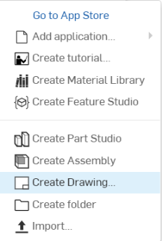
En el menú de la pestaña Crear:
Haga clic en el icono del signo más y, a continuación, seleccione Crear dibujo:
El dibujo rellenará su nombre basándose en el nombre de la pieza, curva o superficie existentes. Puede editar el nombre del dibujo haciendo clic en el nombre existente (que se muestra resaltado a continuación) en la parte superior del cuadro de diálogo Crear dibujo y escribiendo su nombre preferido:
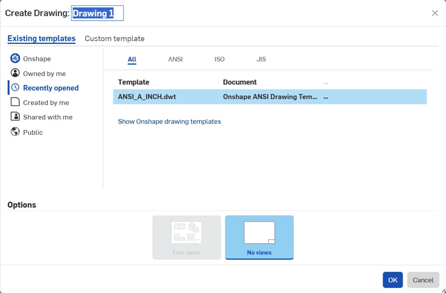
Click OK and the drawing is create without any views (empty).
Crear a partir de archivos de dibujos existentes
Importe un archivo de dibujo existente en formato .DWG o .DXF. Puede importar desde la página Documentos y desde dentro de un documento.
Al importar desde la página Documentos, se crea un nuevo documento:
- Hacer clic en el botón Crear en la esquina superior izquierda de la página:
Crear
- En el menú desplegable, hacer clic en Importar archivos...
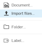
- Seleccione el archivo .DWG o .DXF.
- Seleccione un propietario para el documento (si está disponible).
- Observe el nuevo documento que aparece en la página Documentos. (El nombre del documento es el mismo que el nombre del archivo).
Al importar desde un documento:
- Haga clic en y, a continuación,
 Importar.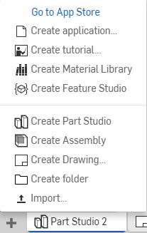
- Seleccione el archivo .DWG o .DXF.
- Anote la nueva pestaña del documento con el mismo nombre que el archivo que importó.
Selección de plantillas
Se debe especificar una plantilla al crear el dibujo y determina los valores de las variables de sistema iniciales, el tamaño de chapa, las entidades de borde, las unidades, los estándares y otras propiedades del dibujo.
Onshape posee y proporciona plantillas disponibles públicamente con nombres como Plantillas de dibujos ANSI Onshape, Plantillas de dibujo ISO de Onshape, etc. Para ver las plantillas Onshape, seleccione el filtro Onshape.
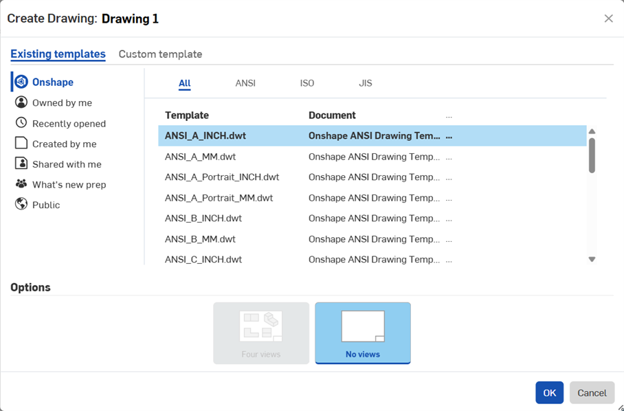
Puede crear sus propias plantillas personalizadas. También puede especificar si quiere crear cuatro vistas estándar o comenzar sin vistas. Para cambiar el color de fondo de un dibujo, acceda a los ajustes en Preferencias.
Para restringir la búsqueda de la plantilla deseada, puede usar lo siguiente:
- Filtros: a la izquierda del cuadro de diálogo, seleccione un filtro (similar a los filtros que se encuentran en la página Documentos). Seleccione un filtro para acotar la lista de plantillas o para ordenarla:
- Abierto recientemente: Enumerar las plantillas en el orden de los utilizados más recientemente
- Onshape: Enumerar las plantillas proporcionadas por Onshape
- Mis plantillas: Mostrar todas las plantillas creadas por usted o compartidas con usted por otro usuario (seleccione el subfiltro Creado por mí o Compartido conmigo), estos incluyen todos los archivos .DWT de documentos para los que tenga permiso de lectura.
- Público: Mostrar todas las plantillas hechas públicas por otros usuarios de Onshape
- Equipos y compañías: Si pertenece a un equipo o compañía, esos nombres aparecen en esta lista. Haga clic en un nombre para ver las plantillas disponibles
- Standards - Across the top/right of the dialog, select a standards acronym to reduce the list of templates to only those of the selected standards format:
- All - List templates in all supported standards
- ANSI - List only ANSI standard templates (American National Standards Institute). Note that these templates configure the drawing for third angle view projection with inch or millimeter dimension units.
- ISO - List only ISO standard templates (International Organization for Standardization). Note that these templates configure the drawing for first angle view projection and millimeter dimension units.
- JIS - List only JIS standard templates (Japanese Institute for Standardization).
Sólo se muestran las plantillas del estándar seleccionado y en el filtro seleccionado.
Qué sigue
Una vez que tenga un dibujo (vacío o con vistas predeterminadas), podrá realizar lo siguiente:
- Añada dimensiones, consulte Dimensiones.
- Añada dimensiones, consulte Dimensiones.
- Añada notas, consulte Notas.
- Si la geometría subyacente cambia, es posible que desee actualizar el dibujo, consulte Actualización de un dibujo.
- Exportación de un dibujo.
- Añada más hojas; consulte Sábanas.