 Eckenfreistich aus Blechecke
![]()
![]()
![]()
Sie können durch Anwenden einer Verrundung oder Fase eine Ecke bei Blechteilen ausbrechen. Wählen Sie eine Eckkante oder einen Eckpunkt aus und geben Sie die Art und den Abstand des Eckenfreistichs an. Am besten verwenden Sie dieses Feature nach Fertigstellung aller Flansche und Verbindungen des Blechmodells.
Einer der letzten Schritte bei Blechkonstruktionen besteht im Abmildern von scharfen Ecken, um Verletzungen und Widerhaken zu vermeiden. Erledigen Sie das mit dem Onshape-Feature für den Eckenfreistich aus Blechecken, mit dem Sie allen ausgewählten Ecken eine Verrundung oder Fase hinzufügen können.
Eckenfreistiche sollten Sie ausschließlich auf die endgültigen Features eines Blechbauteils anwenden. Wurde ein Eckenfreistich angewendet, können Sie die Verbindungstypen und den Stil nicht mehr ändern.
Eckenfreistiche werden auf alle Ecken eines Blechbauteils angewendet, auch für Ecken, die durch Biegeentlastungsschnitte entstehen.
Beginnen Sie mit einem neuen Eckenfreistich-Feature. Wählen Sie entweder die Verrundungs- oder Fase-Registerkarte aus. Wählen Sie dann bei einem Blechbauteil mindestens eine Eckkante oder einen Eckpunkt aus. Die Ecken können im geformten oder abgeflachten Zustand ausgewählt werden.
Wählen Sie zum Messen einer Verrundung entweder den Radius oder die Breite aus. Stellen Sie außerdem die Steueroption für die Verrundung entweder auf „Abstand“, „Konisch“ oder „Krümmung“ ein.
Stellen Sie den Radius- oder Breitenwert ein, um die Verrundung zu bemaßen. Geben Sie für eine konische Verrundung den Rho-Wert an und für eine auf einer Krümmung basierenden Verrundung die Größe.
Für eine Verrundung, die aus zwei ineinander übergehenden Radien besteht, aktivieren Sie „Asymmetrisch“ und geben Sie den zweiten Radius ein. Außerdem gibt es eine Umschaltfunktion mit den Pfeilen „Asymmetrisch umdrehen“.
Bei den Optionen „Abstand“ und „Konisch“ können Sie einen Kantenüberlauf erlauben. Wenn Sie diese Option aktivieren, kann das Verrundungs-Feature die Kanten auf der verrundeten Fläche verändern und so eine glatte, kontinuierliche Oberfläche erzeugen. Wenn Sie diese Option nicht aktivieren, behält Onshape die Kanten der verrundeten Fläche bei.
Stellen Sie für eine Fase die Messung auf „Versatz“ oder „Tangente“ ein. Wählen Sie dann einen Fasentyp aus. Bei gleichem Abstand erstreckt sich die Fase in beiden Richtungen um den gleichen Abstand von der Kante. Zwei Abstände verlängern die Fase um den jeweils eingegebenen Abstandswert. Abstand und Winkel verlängern die Fase um einen bestimmten Abstand in die eine Richtung sowie um einen bestimmten Winkel in die andere Richtung. Bei diesen beiden Optionen können Sie den Pfeil in die entgegengesetzte Richtung umschalten, um die Seite zu wechseln.
So erstellen Sie einen verrundeten Eckenfreistich bei einem Blechmodell:
- Klicken Sie in einem Part Studio mit einem vorhandenen Blechmodell auf Eckenfreistich (
 ).
). 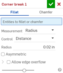
- Wählen Sie den Eckenfreistich-Typ Verrundung aus.
- Wählen Sie im Grafikbereich einen Eckkante oder einen Eckpunkt auf dem Blechmodell aus. Eine Eckkante oder ein Eckpunkt kann auch im Abschnitt Blechmodell und flache Ansicht ausgewählt werden.
- Wählen Sie einen Messtyp aus:
- Radius: Geben Sie die Radienbemaßung der Verrundung an.
- Breite: Geben Sie den Abstand zwischen den beiden Enden der Verrundung an (eine konstante Breite).
- Wählen Sie einen Steuerungstyp aus:
- Abstand: Die Verrundung hat eine Kreiskante mit dem eingegebenen Radiuswert. Onshape merkt sich diesen Wert, wenn neue Verrundungen erstellt werden.
- Konisch: Die Verrundung erhält beim eingegebenen Radiuswert eine konische Kante. Sie können optional auch einen Rho-Wert zur Definition der Verrundungsart eingeben:

Rho-Werte: 0,25 (links, elliptische Kurve); 0,5 (Mitte, parabolische Kurve); 0,999 (rechts, hyperbolische Kurve – vergrößert)
- Krümmung: Die Verrundung entspricht der Krümmung der umgebenden Kanten mit einem Radiuswert, den Sie eingeben, und einem optionalen Größenwert zwischen 0 und 0,999 zur Anpassung der Tangentialität. Aktivieren Sie die Zebrastreifen (im Menü „Analyse-Tools anzeigen“), um die Tangente deutlicher zu sehen:
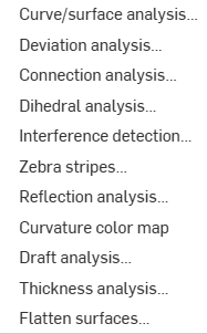
Wenn Sie einen Radiuswert eingeben, können Sie auch den Ziehen-Manipulator (im Bild unten durch einen Pfeil dargestellt) verwenden, um die Verrundung zu visualisieren und sich einem Schätzungswert anzunähern:
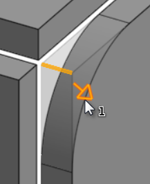
Onshape merkt sich den ausgewählten Messtyp und Wert und öffnet bei nachfolgenden Operationen das Dialogfenster mit der zuletzt ausgewählten Option.
- Aktivieren Sie Asymmetrisch und geben Sie einen zweiten Radius ein, um an einem Ende der Verrundungskante einen anderen Radiuswert zu haben. Klicken Sie auf den Pfeil Asymmetrisch umdrehen, um das andere Ende der Verrundung als zweite (asymmetrische) Verrundungskante zu verwenden.
- Standardmäßig ist die Option Kantenüberlauf erlauben deaktiviert. Aktivieren Sie sie, damit die Tangentialkanten bei Bedarf aus der Verrundungsoberfläche gelöscht werden können. Die Kanten, die standardmäßig erzeugt werden, beschränken die Richtung der Verrundung entlang der Verrundungskanten strikt. Wenn die Option Kantenüberlauf erlauben aktiviert ist, kann die Verrundung die Kanten auf der Fläche, die durch die Verrundung erzeugt wird, so verändern, dass eine glatte, durchgehende Oberfläche entsteht. Wenn die Option deaktiviert ist, werden die Kanten der verrundeten Fläche beibehalten und das Bauteil ist insgesamt freier beweglich.
Klicken Sie auf die Dropdown-Liste „Kantenüberlauf erlauben“, um ein Feld zu öffnen, in dem Sie beizubehaltende Kanten auswählen können.
- Klicken Sie auf das Häkchen (
 ), um das neue Eckenfreistich-Feature zu akzeptieren.
So erstellen Sie einen gefasten Eckenfreistich bei einem Blechmodell:
- Klicken Sie in einem Part Studio mit einem vorhandenen Blechmodell auf Eckenfreistich (
 ).
). 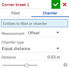
- Wählen Sie den Eckenfreistich-Typ Fase aus.
- Wählen Sie im Grafikbereich einen Eckkante oder einen Eckpunkt auf dem Blechmodell aus. Eine Eckkante oder ein Eckpunkt kann auch im Abschnitt Blechmodell und flache Ansicht ausgewählt werden.
- Wählen Sie einen Messtyp aus:
- Versatz: legt die im Abstand-Feld eingegebene Entfernung von der Startkante zur Fase fest. Diese Option ist kantenabhängig. Die Berechnung beginnt bei der ersten Auswahl und durchläuft dann die Kette .
- Tangential: legt die im Abstand-Feld eingegebene Entfernung für den Schnittpunkt zur Tangente der beiden benachbarten Flächen zur Fase fest. Diese Option ist NICHT kantenabhängig.
- Wählen Sie einen Fasentyp aus:
- Gleicher Abstand: Die Fase wird in beiden Richtungen im gleichen Abstand von der Kante erweitert.
- Zwei Abstände: Die Fase wird in jeder Richtung um unterschiedliche Abstände erweitert.
- Abstand und Winkel: Die Fase wird in der einen Richtung um den angegebenen Abstand erweitert und in der anderen Richtung um den angegebenen Winkel erweitert.
Onshape merkt sich die Auswahl für den Fasentyp und öffnet bei nachfolgenden Operationen das Dialogfenster mit der zuletzt ausgewählten Option.
- Geben Sie den Abstand bzw. die Abstände (je nach Auswahl) für die Fase ein. Onshape verwendet standardmäßig 45 Grad für den Winkel, merkt sich jedoch den zuletzt eingegebenen Abstandswert für Fasen mit gleichem Abstand oder Abstands- und Winkelfasen.
- Wenn Sie Zwei Abstände oder Abstand und Winkel ausgewählt haben, können Sie mit der Pfeiltaste die Richtung aller Kanten umkehren. Alternativ können Sie im Feld Richtungsüberschreibungen einzelne Kanten angeben, deren Richtung umgedreht werden soll.
- Klicken Sie auf das Häkchen (
 ), um das neue Eckenfreistich-Feature zu akzeptieren.
-
Nachdem ein Eckenfreistich-Feature angewendet wurde, können der Typ (Schlitz oder Biegung) und der Stil (Kantenverbindung oder Stoßverbindung) des Modells in der Blechtabelle und der flachen Ansicht nicht mehr bearbeitet werden. Es wird empfohlen, alle Eckenfreistich-Features hinzuzufügen, nachdem alle Änderungen an den Flanschen und Verbindungen des Blechmodells abgeschlossen sind.
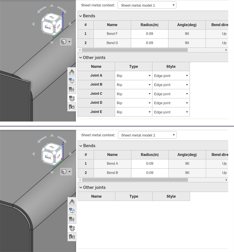
Oben: vor dem Anwenden des Eckenfreistich-Features. Unten: nach dem Anwenden des Eckenfreistich-Features.
-
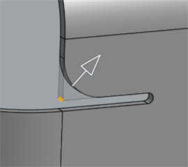
Sie können den Eckenfreistich verwenden, um neben Ecken auch Rundungen oder Fasen auf Biegeentlastungskanten und Eckenpunkte anzuwenden:
-
Es ist nicht möglich, mehrere Verrundungen, Fasen oder eine Kombination aus beidem an Ecken mithilfe eines einzigen Eckenfreistich-Features hinzuzufügen. Erstellen Sie ein zusätzliches Eckenfreistich-Feature, um zu einem beliebigen Eckpunkt oder einer Kante eines vorherigen Eckenfreistich-Features eine zusätzliche Verrundung oder eine weitere Fase hinzuzufügen:
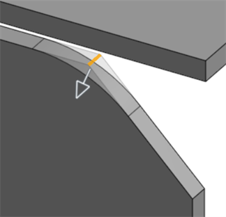
Mit einem zweiten Eckenfreistich-Feature auf eine gefaste Kante angewendete Verrundung
Wenn ein Blechmodell aktiv ist (während der Erstellung oder Bearbeitung), stehen zusätzliche Tools zur Verfügung:
-
 Flansch: Erstellen Sie eine Wand für jede ausgewählte Kante, die durch eine Biegung mit der ausgewählten Kante verbunden ist.
 -
 Blechkantenrand: Erstellen Sie auf einem vorhandenen Blechteil einen Blechkantenrand für jede ausgewählte Kante/Fläche.
 -
 Zunge: Fügen Sie eine Zunge zu einem Blechflansch hinzu.
 -
 Biegen: zum Biegen eines Blechmodells entlang einer Referenzlinie mit zusätzlichen Optionen zur Biegekontrolle.
 -
 Form: Erstellen Sie Form-Features auf vorhandenen Blechmodellen. Formen können aus dem aktuellen Dokument, anderen Dokumenten oder einer vordefinierten Bibliothek von Blechformen ausgewählt werden.
 -
 Loft - Create sheet metal models that connect two profiles.
 -
 Verbindung erstellen: Wandeln Sie die Schnittstelle von zwei Wänden in ein Verbindungs-Feature um, entweder in eine Biegung (Wände, die durch zylindrische Geometrie verbunden sind) oder in einen Schlitz (kleiner Spalt zwischen den beiden Wänden).
 -
 Ecke: Ändern Sie einen Eckentyp und den Freischnitt-Maßstab.
 -
 Biegungs-Freischnitt: Ändern Sie einen Biegungs-Freischnitt (den kleinen Schnitt am Berührungspunkt zwischen Biegungsende und freier Kante), die Tiefe und die Freischnitt-Breite.
 -
 Verbindung ändern: zum Ändern einer bestehenden Verbindung. Wandeln Sie zum Beispiel eine Biegung in eine Rippe um. Diese Option ist derzeit über die Abwicklungstabelle verfügbar.
 -
 Eckenfreistich: zum Ausbrechen einer Ecke bei Blechteilen, indem Sie eine Verrundung oder Fase anwenden. Wählen Sie eine Eckkante oder einen Eckpunkt aus und geben Sie die Art und den Abstand des Eckenfreistichs an. Es wird empfohlen, dieses Feature nach Fertigstellung aller Flansche und Verbindungen des Blechmodells zu verwenden.
 -
 Blechtabelle und flache Ansicht: zum Öffnen und Schließen der Schlitz-/Biegungs-Tabellen und Visualisierung des Modells für die Blechabwicklung. Verwenden Sie diese Tabelle, um die Schlitze in Biegungen und die Biegungen in Schlitze umzuwandeln.
 -
 Blechmodell fertigstellen: schließt (deaktiviert) das Blechmodell. Erstellt ein Feature in der Feature-Liste.
So erstellen Sie einen verrundeten Eckenfreistich bei einem Blechmodell:
- Tippen Sie in einem Part Studio mit einem vorhandenen Blechmodell auf Eckenfreistich (
 ).
). 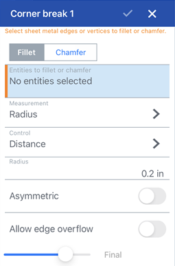
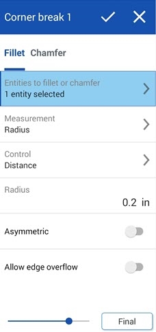
Eckenfreistich: Verrundungs-Dialogfenster für iOS (1. Abb. oben) und Android (2. Abb. oben)
- Tippen Sie für den Eckenfreistich-Typ auf Verrundung.
- Wählen Sie im Grafikbereich eine Eckkante oder einen Eckpunkt auf dem Blechmodell aus.
- Wählen Sie einen Messtyp aus:
- Radius: Geben Sie die Radienbemaßung der Verrundung an.
- Breite: Geben Sie den Abstand zwischen den beiden Enden der Verrundung an (eine konstante Breite).
- Wählen Sie einen Steuerungstyp aus:
- Abstand: Die Verrundung hat eine Kreiskante mit dem eingegebenen Radiuswert. Onshape merkt sich diesen Wert, wenn neue Verrundungen erstellt werden.
- Konisch: Die Verrundung erhält beim eingegebenen Radiuswert eine konische Kante. Sie können optional auch einen Rho-Wert zur Definition der Verrundungsart eingeben:

Rho values: 0.25 (left; elliptical curve); 0.5 (middle; parabolic curve); 0.999 (right; hyperbolic curve - zoomed in)
- Krümmung: Die Verrundung entspricht der Krümmung der umgebenden Kanten mit dem Radiuswert, den Sie eingeben, und einem optionalen Größenwert zwischen 0 und 0,999 zur Anpassung der Tangentialität.
Wenn Sie einen Radiuswert eingeben, können Sie auch den Ziehen-Manipulator (im Bild unten durch einen Pfeil dargestellt) verwenden, um die Verrundung zu visualisieren und sich einem Schätzungswert anzunähern:
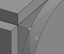
- Schalten Sie auf Asymmetrisch um und geben Sie einen zweiten Radius ein, damit ein Ende der Verrundungskante einen anderen Radiuswert hat. Schalten Sie den Pfeil Asymmetrisch umdrehen um, um das andere Ende der Verrundung als zweite (asymmetrische) Verrundungskante zu verwenden.
- Standardmäßig ist die Option Kantenüberlauf erlauben nicht aktiviert. Schalten Sie auf diese Option um, damit die Tangentialkanten bei Bedarf aus der Verrundungsoberfläche „gelöscht“ werden können. Die Kanten, die standardmäßig erzeugt werden, schränken die Richtung der Verrundung entlang der Verrundungskanten strikt ein. Wurde die Option Kantenüberlauf erlauben mit der Umschaltfunktion aktiviert, kann die Verrundung die Kanten auf der Fläche, die durch die Verrundung erzeugt wird, so verändern, dass eine glatte, durchgehende Oberfläche entsteht. Wurde die Option mit der Umschaltfunktion deaktiviert, werden die Kanten der verrundeten Fläche beibehalten und das Bauteil ist insgesamt freier beweglich.
Tippen Sie auf das Feld Beizubehaltende Kanten und wählen Sie im Grafikbereich alle Kanten aus, die Sie weiterhin haben möchten.
- Tippen Sie auf das Häkchen, um das neue Eckenfreistich-Feature zu akzeptieren.
So erstellen Sie einen gefasten Eckenfreistich bei einem Blechmodell:
- Tippen Sie in einem Part Studio mit einem vorhandenen Blechmodell auf Eckenfreistich (
 ).
). 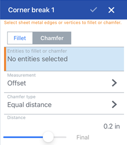
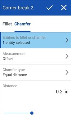
Eckenfreistich: Fase-Dialogfenster für iOS (1. Abb. oben) und Android (2. Abb. oben)
- Tippen Sie für den Eckenfreistich-Typ auf Fase.
- Wählen Sie im Grafikbereich eine Eckkante oder einen Eckpunkt auf dem Blechmodell aus.
- Wählen Sie einen Messtyp aus:
- Versatz: legt die im Abstand-Feld eingegebene Entfernung von der Startkante zur Fase fest. Diese Option ist kantenabhängig. Die Berechnung beginnt bei der ersten Auswahl und durchläuft dann die Kette .
- Tangential: legt die im Abstand-Feld eingegebene Entfernung für den Schnittpunkt zur Tangente der beiden benachbarten Flächen zur Fase fest. Diese Option ist NICHT kantenabhängig.
- Wählen Sie einen Fasentyp aus:
- Gleicher Abstand: Die Fase wird in beiden Richtungen im gleichen Abstand von der Kante erweitert.
- Zwei Abstände: Die Fase wird in jeder Richtung um unterschiedliche Abstände erweitert.
- Abstand und Winkel: Die Fase wird in der einen Richtung um den angegebenen Abstand erweitert und in der anderen Richtung um den angegebenen Winkel erweitert.
- Geben Sie den Abstand bzw. die Abstände (je nach Auswahl) für die Fase ein. Onshape verwendet standardmäßig 45 Grad für den Winkel, merkt sich jedoch den zuletzt eingegebenen Abstandswert für Fasen mit gleichem Abstand oder Abstands- und Winkelfasen.
- Wenn Sie Zwei Abstände oder Abstand und Winkel ausgewählt haben, können Sie mit der Pfeiltaste die Richtung aller Kanten umkehren. Alternativ können Sie im Feld Richtungsüberschreibungen einzelne Kanten angeben, deren Richtung umgedreht werden soll.
- Tippen Sie auf das Häkchen, um das neue Eckenfreistich-Feature zu akzeptieren.
-
Nachdem ein Eckenfreistich-Feature angewendet wurde, können der Typ (Schlitz oder Biegung) und der Stil (Kantenverbindung oder Stoßverbindung) des Modells in der Blechtabelle und der flachen Ansicht nicht mehr bearbeitet werden. Es wird empfohlen, alle Eckenfreistich-Features hinzuzufügen, nachdem alle Änderungen an den Flanschen und Verbindungen des Blechmodells abgeschlossen sind.
-
Sie können den Eckenfreistich verwenden, um neben Ecken auch Rundungen oder Fasen auf Biegeentlastungskanten und Eckenpunkte anzuwenden:

-
Es ist nicht möglich, mehrere Verrundungen, Fasen oder eine Kombination aus beidem an Ecken mithilfe eines einzigen Eckenfreistich-Features hinzuzufügen. Erstellen Sie ein zusätzliches Eckenfreistich-Feature, um zu einem beliebigen Eckpunkt oder einer Kante eines vorherigen Eckenfreistich-Features eine zusätzliche Verrundung oder eine weitere Fase hinzuzufügen:

Mit einem zweiten Eckenfreistich-Feature auf eine gefaste Kante angewendete Verrundung
Wenn ein Blechmodell aktiv ist (während der Erstellung oder Bearbeitung), stehen zusätzliche Tools zur Verfügung:
-
 Flansch: Erstellen Sie eine Wand für jede ausgewählte Kante, die durch eine Biegung mit der ausgewählten Kante verbunden ist.
 -
 Zunge: Fügen Sie eine Zunge zu einem Blechflansch hinzu.
 -
 Verbindung erstellen: Wandeln Sie die Schnittstelle von zwei Wänden in ein Verbindungs-Feature um, entweder in eine Biegung (Wände, die durch zylindrische Geometrie verbunden sind) oder in einen Schlitz (kleiner Spalt zwischen den beiden Wänden).
 -
 Ecke: Ändern Sie einen Eckentyp und den Freischnitt-Maßstab.
 -
 Biegungs-Freischnitt: Ändern Sie einen Biegungs-Freischnitt (den kleinen Schnitt am Berührungspunkt zwischen Biegungsende und freier Kante), die Tiefe und die Freischnitt-Breite.
 -
 Loft - View and modify sheet metal models that connect two profiles.
 -
 Eckenfreistich: zum Ausbrechen einer Ecke bei Blechteilen, indem Sie eine Verrundung oder Fase anwenden. Wählen Sie eine Eckkante oder einen Eckpunkt aus und geben Sie die Art und den Abstand des Eckenfreistichs an. Es wird empfohlen, dieses Feature nach Fertigstellung aller Flansche und Verbindungen des Blechmodells zu verwenden.
 -
 Blechmodell fertigstellen: schließt (deaktiviert) das Blechmodell. Erstellt ein Feature in der Feature-Liste.