Working with Imported CAD
![]()
![]()
![]()
Designing from scratch in Onshape isn't the only way to build and refine your CAD models. If you have existing CAD data in another system, you can import that data into Onshape and continue designing here.
Onshape accepts data from many other systems, the most popular and well-translated being Parasolid files. For more information on file types accepted and how to import your data into Onshape, see Supported File Formats and Importing Files.
This topic explains how to proceed and what tools are available after you've imported your existing CAD data into Onshape.
Onshape tools
Due to system differences, data imported into Onshape may translate in with faults, or no parametric history, or as a series of surfaces or parts instead of a solid or cohesive body. While you have some options for how data will be handled upon import, there remain some things beyond control. However, Onshape has tools that will help you move forward with your imported data and work with it to continue designing, sharing, and releasing designs.
The tools provided to help you work with imported CAD data and covered in this topic include the following:
Onshape enables you to import the following faceted file formats for visualization and referencing. Mesh points are able to be used as vertices for creating planes.
-
Parasolid Mesh
-
STL
-
OBJ
-
GLTF
-
3MF
A mesh is imported into Onshape Part Studio, and shown in the Parts lists under Meshes (below Surfaces).
You can view and reference meshes, but you can not edit them.
Mesh vertex selections are not parametric and are not associated with mesh vertices. Instead, their location is recorded. As a result any edit to the imported mesh (for example, a transformation) does not update their positions.
You can change the mesh units during the import process and from the units dropdown within the tab menu, shown in the second image below:
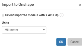
During import, above
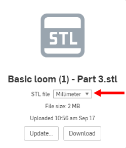
Within the imported tab, above
What you can do
Once a mesh is imported into an Onshape Part Studio, you have the ability to:
- Create a three point plane using mesh points
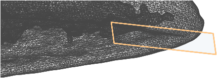
- Measure the surface area, distances to and from mesh points, and mass properties for solid meshes


- Project mesh points in a sketch (via the Use tool)
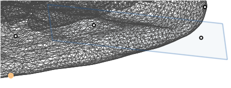
- Create Mate connectors at mesh points
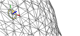
- Reference a mesh point for ‘Up to vertex’ operations (as in Extrude)
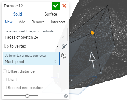
For more information on working with mesh in mixed modeling, see Mixed Modeling.
Onshape provides a tool for identifying holes and disconnects in imported models that may require repair: Highlight boundary edges.
Highlight boundary edges can be found as a menu option in the Camera and render options dropdown: Highlight boundary edges.
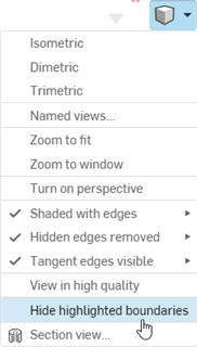
When Highlight boundary edges is selected, boundary (or laminar) edges are displayed in solid red lines (for visible edges) and dashed red lines (for hidden edges).
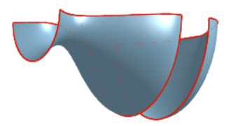
To repair these surfaces, you can use any number or combination of tools in Onshape, for example:
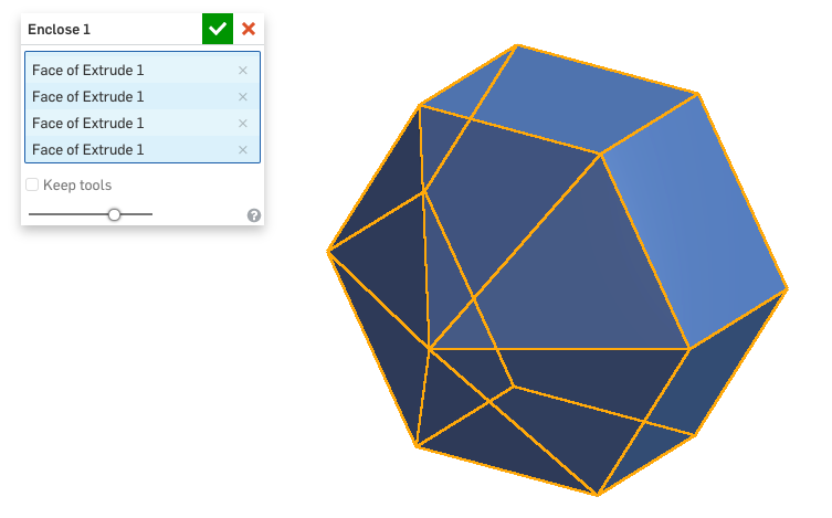
- Enclose - Select surfaces, faces, and parts that enclose a region to create a new part.
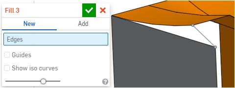
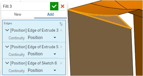
- Fill
- Create a surface bounded by a closed set of curves or edges.
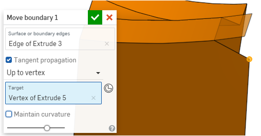
- Move boundary
- Move boundary edges of a surface in order to extend or trim it.
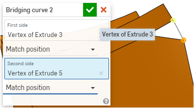
- Bridging curve
- Create a curve connecting any two points or vertices.
- Composite curve
- Create curves from selected edges, sketch entities and other curves.

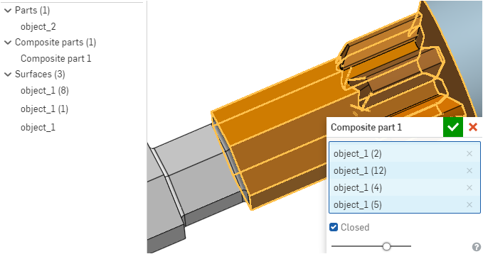
When parts or surfaces are fractured upon import, or when you want separate bodies to be treated as a cohesive unit, create either a closed or open composite part (one which consumes the entities, or does not, respectively).
For example, if your design is fractured upon import, as in this example below where one section of the design is rendered as multiple surfaces, you can select the fractured entities and combine them to form a composite part:
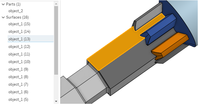
The selected surface, "object_1(13)," is cross-highlighted in the model - but suppose you want all the surfaces to be one part. You can select them and create a composite part, shown below:
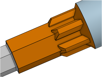
The part, after the feature is accepted:
Imported geometry does not carry with it the parametric history so there may be times when you need to use Onshape's direct editing tools to continue modeling an imported design.
For example, after you import a part, the holes might be in the wrong places. You can use the direct editing tools to remove the original holes and then make new holes in the proper locations on the model.
Another example is fixing imported geometry when a face is missing or has an error, or you have to delete a face and recreate it. In the example below, the knob on the top of the cap needs to be reshaped, so the Delete face tool is used:
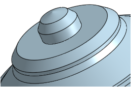
The imported cap with knob, above
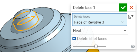
The selected face to remove, above
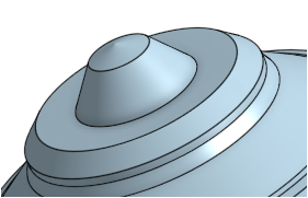
The resulting cap with new face, above
After the part is imported, an Import feature ( ![]() ) is displayed in the Features list (Import 1 below):
) is displayed in the Features list (Import 1 below):
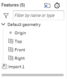
To edit the feature post import:
-
Double-click the Import feature or right-click on the Import feature and select Edit from the context menu.
-
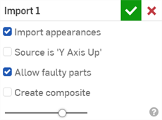
The Import dialog opens:
-
Adjust the following settings. These settings can be enabled/disabled at any time.
-
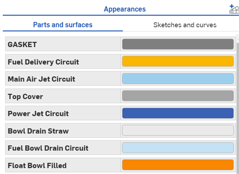
Import appearances - Check to have the original appearances imported. These appearances are accessed by clicking the Appearance panel icon (
 ) to open the Appearances panel on the right. Uncheck to remove all appearances from the imported part. See Customizing Parts, Faces, Features, and Sketches: Appearance for more information.
-
Source is 'Y Axis Up' - Onshape's up axis is the Z axis. When unchecked, the models are imported with the Z axis up. For CAD files from systems where the up axis is the Y axis, check this box to import the models with the Y axis up. Onshape supports the Y Axis Up option for all systems/files except Autodesk (.ipt) and CATIA (.catpart).
-
Allow faulty parts - Check to allow faulty parts. Uncheck to disallow faulty parts from the imported part. Faulty parts are those with a topology issue. Faulty parts show the part or surface in red in the Parts list.
-
Create composite - If checked, a composite part is manually created when importing neutral CAD file (.step or .x_t, for example) consisting of multiple non-solid bodies. All parts in the imported Part Studio become a single closed composite part, regardless of whether or not the parts belong to the same body.
-
After a part is imported, you can update it should the part change in the source file.
When the Split into multiple documents option is selected, the top level Assembly file cannot be updated. See Importing files for more information.
To update a previously imported part:
- Export the part once more from the other CAD system. (Presumably this part has been changed since the first time it was exported.)
- In the document into which the exported part was previously imported, do one of the following:
- Open the Part Studio that holds the part, right-click the Import entry in the Features list and select Update.
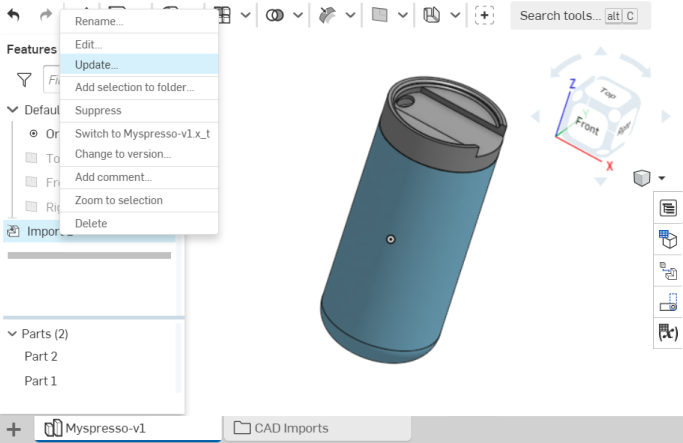
Select the export file and click Open. The Import feature updates to the updated part.
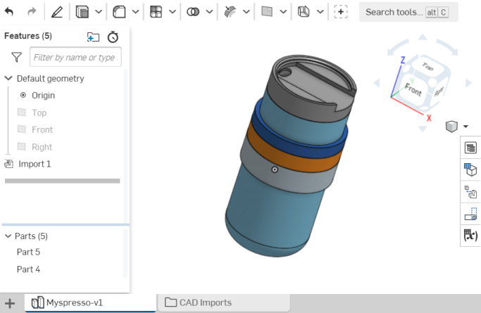
- Click the CAD imports folder and select the tab of the imported file. Click Update (shown below), select the export file and click Open. The new file name is displayed and the part is updated in the Part Studio.
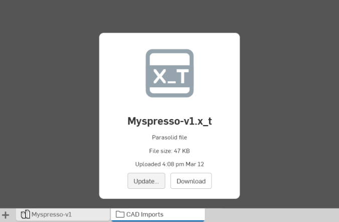
If a document has not been upgraded after Onshape release 1.93, then this Update button will not upgrade the imported feature but will instead make a new Part Studio containing the new/upgraded part. If the document has been upgraded since Onshape release 1.93, when the Update button is clicked, the imported blob is updated with the new file and the updated geometry propagates to the imported feature.
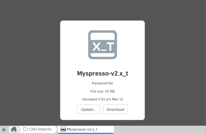
In both cases, the Part Studio containing the Import feature is updated.
- Open the Part Studio that holds the part, right-click the Import entry in the Features list and select Update.
What is updated
When a part is updated, all features and changes made to the part in the source system are updated in the target Part Studio. If the part has been modified in the target Part Studio, by applying features to it, those features are reapplied to the updated part where possible.
For example, if a fillet has been applied to the part in the target Part Studio, that fillet is reapplied to the updated part where possible. There may be modeling changes made to the source part that result in applied features in the target Part Studio from regenerating successfully. These features will be shown in an error state in the Features list.
Only the Part Studio is updated. Updating an Assembly is not currently supported. The Assembly (and all instances) remains as it was during the original import after an Update is performed.
Sometimes when you import a project into Onshape, commonly used components may become duplicated. Since duplication of components is an undesirable situation, in Onshape you can instead use multiple references to the one component.
For organizational purposes, it's best to move the common component to its own document, so all users can find it easily without disturbing projects in process. To move a component out of one document and into another:
- Select the name of the component in the Part Studio's Parts list.
- Right-click and select Export.
- On the Documents page, click Create and then Import.
- Import the file you just exported, which will create a new document.
- In the original document, locate the part in its original Part Studio.
- Delete the part from the Part Studio.
Note that in this document, all references to that Part (in assemblies) will 'break' and appear red.
- In each assembly that references that part, select each reference to the part in the Instances list, right-click and select Replace instances.
- In the Replace instance dialog, navigate to the Created by me document section, and select the new source document containing the common component.
- Now the component will be inserted where it was referenced in the assembly, but with a link icon next to it. The link icon indicates that the instance is referenced from another document.
The advantage to this workflow is that you now have one component instanced many times. If you want to make a change to the component, do it in the source document and then you can decide if and when to update the instances referenced in other documents. This saves you the trouble of reinserting and mating multiple components unnecessarily, as well as aid you in keeping components up to date easily.
For a more in-depth example, see this Onshape Tech Tip.
When deleting imported files, you will see a warning about which Part Studios the deletion will impact:
