 Tag
Tag
![]()
Tag sketch profile entities for use in Frames or parts to add or remove from Sheet metal forms. Select geometry, define orientation, and add properties.
Onshape provides a library of standard structural profiles built directly into the Frame feature. However, there might be times when you need to create a custom library of frame profiles. It is very easy to create and share custom profiles to use with the Frames feature. This video explores how to do this by defining a library of sketches, configuring the profile for different size options, and tagging the profile so that the Cut list table populates with the segments and segment properties.
To create a new profile library, create a new Onshape document. Organize profiles in one or more library documents. Place the library document in a folder at the root of the company or enterprise. This practice makes it easy to share with other users who need to use the profiles.
Create a sketch of the profile in a Part Studio. Create a unique Part Studio for each profile sketch. While sketching, consider how you wish to align the profile. If necessary, add sketch points to serve as additional alignment points. Define the sketch with dimensions and relations. Use variables when defining the sketch dimensions you intend to configure for different profile size options. Variables make it easy to identify the critical values of the profile. Rename the Part Studio and the sketch to describe the profile. The unique name makes it easier for users to understand the intention of your profile. When selecting the profile, the Part Studio name displays at the top level of the dialog, and the sketch name displays below.
If the profile is available in several different sizes with the same shape, configure the sketch dimensions or variable values. Build configuration tables using configuration inputs for each size. Then, configure the dimensions or variables, if used. Edit the sketch, right-click on each dimension to drive the configuration, and select Configure dimension. If you define the sketch with variables, edit the variable, right-click on the value, and select Configure. Edit the values in the configuration table.
Next, start a new Tag feature and select Frame from the dropdown. The Tag feature adds properties to the profile, so when it is used in a Frame feature, the Cut list table displays column headers like Standard and Description, and populates values for those properties.
Select the sketch profile. You can select it from the graphics area or the Features list. If additional alignment points are required, expand the selection field and select points in the sketch to serve as alignment points. Then input numeric or text strings for Standard and Description. If these fields are left blank, that column is not added to the Cut list when the profile is used, or that cell displays “Not set” if other profiles used in the structure have that column header defined. Both Standard and Description inputs can be configured. Right-click on the field in the Tag profile dialog and choose Configure. Then edit the cells in the Configuration table.
To supply more properties for the profile, click Add Column and enter Header and Value information. Repeat as needed to add additional columns to the Cut list table. Click the checkmark when done. These properties cannot be configured. Click the Delete button (X) in the dialog to remove any columns.
Click the checkmark to accept the Tag feature. This profile can now be used with structures contained in this document. Start a new Frame feature in another Part Studio and click the Sketch profile selection in the dialog. In the Current document, select the profile. Adjust the configuration and click Generate to apply the configured values. Then, select the sketch profile.
When building custom profile libraries, keep the profiles in a different document from the designs using them. In this case, version the document that contains the profiles once complete. From then on, the profile can be referenced using linked documents. In this example, a different document contains the custom profiles. Click Other documents, navigate to the document, and select the sketch profile.
To allow other users access to custom profiles, the document or folder containing the profiles must be shared. Users who need to reference the custom profiles in the Frames feature need view and link permissions only. Users who are helping manage the custom profiles need edit and link permissions. Using teams to share is a great way to ensure the right people have access and makes managing access easier. When personnel changes occur in the organization, it is easier to manage adding or removing users on a team than on individual shares.
To tag a profile you have created or modified and use the information in the Cut list table as additional columns:
- Click
the Tag icon (
 )
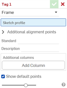
to open the Tag dialog:
-
Select Frame for the tag purpose.
- In the Sketch profile field, select the sketch in the Feature list that serves as the sketch for the profile.
-
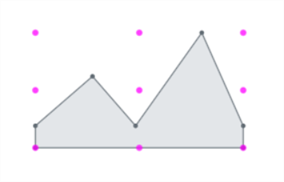
By default, Show default points is enabled in the dialog. This places a magenta-colored 9-point alignment grid overlaid on the sketch profile. Uncheck this option to hide the alignment points.
-
In the Additional alignment points field, select any other points in your sketch you want to use for alignment.
- In the Standard field, enter the value to display in the Standard column of the Cut list table.
- In the Description field, enter a description to display in the Description column of the Cut list table.
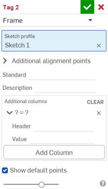
- To supply more columns of information for the profile, click Add Column:
-
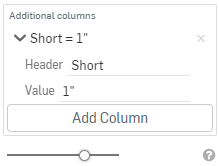
In the Header field, enter the name of the new column header to appear in the Cut list table of the additional profile, and the value:
-
Click Add Column to add another column/value pair to the Cut list table.
-
Click the checkmark (
 ).
).
Best practice is to tag a profile, create a version, and reference that version of the profile in the frame.

Notice the new values in the Description column, and the additional column "Short" with corresponding values, above.
The profile's new information appears in the Cut list table after being used in a Frame feature, followed by a Cut list table feature to create the table. Click
![]() on the right side of the window to open the table panel.
on the right side of the window to open the table panel.
Form tags designate non-sheet metal parts to be used as Form features to add or remove material from the sheet metal model.
To tag parts:
- Click
the Tag icon (
 )
to open the Tag dialog:

-
Select Form for the tag purpose:
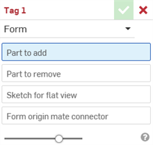
- In the Part to add field, select the part in the Parts list or graphics area from which to add to the sheet metal.
- In the Part to remove field, select the part in the Parts list or graphics area from which to subtract from the sheet metal.
- Select the Sketch for flat view. This is the sketch used for the Sheet metal model's flat view.
- Select the Form origin mate connector. This determines the direction where the form is shaped in the Sheet metal model. Hover over the graphics area model to select an implicit or explicit mate connector. If none is selected, the feature creates one at the Part Studio's origin.
- Click the checkmark (
 ).
).
Do not select a sheet metal part. Select a standard geometric part.
Do not select a sheet metal part. Select a standard geometric part.
You can have only 1 valid form tag feature per Part Studio. Create 1 form per Part Studio.
-
 Frame
- Create a collection of swept bodies sharing a profile, arranged end-to-end.
 -
 Frame trim
- Trim segments as ordered groups.
 -
 Gusset
- Create gussets between adjacent frame segments.
 -
 End cap
- Create one or more end caps for frame segments.
 -
 Cut list
- Create a cut list of all the segments in a frame with their characteristics. This operation also creates an open composite part for the collection.
 -
 Tag
- Tag sketch profile entities for use in Frames or parts to add or subtract from Sheet metal forms. Select geometry, define orientation, and add properties.