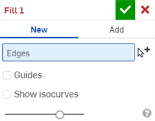
 Fill
Fill
![]()
![]()
![]()
Create a surface (or a part from surfaces) by defining boundaries and refine the surface with boundary conditions (instead of requiring the use of reference surfaces).
The Fill feature connects boundary edges to create surface geometry. Deciding on whether to use Boundary surface, Loft, or Fill feature depends on the application. The Boundary surface and Loft features require 4-sides to the boundaries, whereas the Fill feature can utilize as many boundary segments as needed. This is especially useful when holes and gaps with several surfaces must be patched with a single feature. A Loft or Boundary surface provide more control and result in higher-quality surfaces.
The Fill surface feature can be used to repair imported models, patch the area of a model that contains complex geometry, or simply enclose a surface model to create a solid part. To create a surface with the Fill feature, the sections must have fully connected edges to form a single chain.
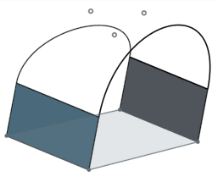
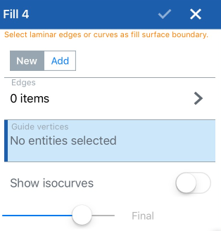
Start a new Fill feature. Select the edges of a part, surface, sketched or 3D curve. As each entity is selected, two red dots indicate the start and end of the selected boundary chain. To create a surface, the boundary must be completely closed. If not, the red dots remain visible in the graphics area. Pay close attention to these indicators. In some situations, a small interruption in the boundary prevents a closed chain. As a best practice, use the Create selection option. Under the Edges tab, select “Loop/Chain connected” to quickly select the entire boundary. Once the boundary has been completely closed, the red dots are removed from the graphics area. A Fill surface can still be created if a portion of a boundary completes a chain but does not stop where it connects to other entities.
The New option creates a new surface and is visible in the Parts list under Surfaces. Add, adds the surface to other surfaces defined in the merge scope. Select Match position, Tangency, or Curvature in the Continuity dropdown to set boundary conditions. If the portion of the boundary is a sketch entity and the option to match tangency is selected, Onshape respects the direction normal to that sketch plane. Interior edges, 3D fit splines, projected curves, and bridging curves can only match position. A composite curve can be used to match tangency or curvature, only when edges of a surface have created the curve. Onshape analyzes the underlying surfaces that form the composite curve and can match the appropriate continuity. When choosing Position, the fill surface maintains G0 continuity to the surrounding geometry. Choosing tangency ensures G1 continuity, and matching curvature ensures G2 continuity. When tangency or curvature are selected, apply finer control by specifying adjacent faces.
A guide for the Fill feature is similar to a guide for a Loft feature for manipulating the surface geometry. Use curves or vertices as guides. Using vertices as a guide, the surface passes through those points while satisfying the boundary conditions. Using curves as a guide, the surface geometry accurately follows specific or sampled points along the curve. Precise follows the guide curve exactly as defined. Sampled takes a sampled number of points that follow the curve the fill surface passes through. This option is helpful if the fill surface is heavily constrained. For this reason, “sampled” may be used to loosen the constraints for the guides and results in a smoother surface. The number of sampling points can be changed by increasing or decreasing the sample size.
Check Show ISO curves to evaluate the flow of the filled surface visually. Adjust the Count value to increase or decrease the amount of curves displayed.
- Click
 .
.
-
Select the edges, which act as the boundaries of the fill.
The Create selection
 tool can be useful when selecting related edges.
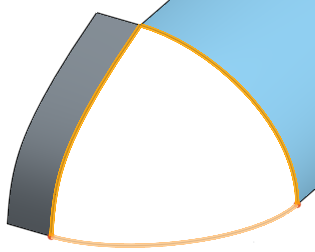
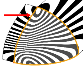
- Optionally, define Continuity for each selected edge or curve (you can select Zebra stripes from the small View cube menu to see the effects):
- Position
- Make edges meet with no tangent or curvature relationship to each other
- Tangency
- Create an implicit tangency (normal to the plane of the selected surface) between the boundaries and the new surface (as if you had a reference surface). This works for sketch selections only, not for other planar curves. Optionally, when selected, the Adjacent faces field is enabled. Pick any face in which underlying geometry is coincident with at least one profile part's curve (the face and edge do not need to intersect or be part of the same part).
- Curvature
- Match the actual curve of the adjacent surface. Optionally, when selected, the Adjacent face field is enabled. Pick any face in which underlying geometry is coincident with at least one profile part's curve (the face and edge do not need to intersect or be part of the same part).
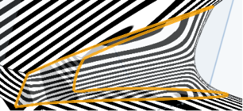
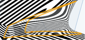
For example, for the left most selected edge, below, each of the Continuity options were selected. Note the differences in the visualization stripes:
Position:
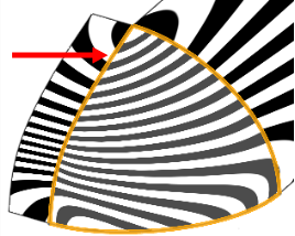
Tangency:
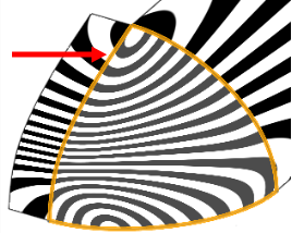
Curvature:
- Select
Guides
(points, vertices, points on a sketch, or curves) with which to influence the shape. The resulting surface intersects these points which will lie in the interior of the boundary. When curves are selected, the surface pushes through the curves and you can select from two types of calculations:
- Sampled
- Uses the Sample Size to determine the number of vertices along the curves are used to calculate the surface. A long Sample size may result in the surface following the entire curve:
Sample size of 3:
Sample size of 10:
Depending on the Sample size, some rippling of the surface may occur.
- Sampled
- Uses the Sample Size to determine the number of vertices along the curves are used to calculate the surface. A long Sample size may result in the surface following the entire curve:
- Precise - Uses the exact curve to form the surface. Note that this option requires very carefully designed and selected curves. See the examples below for more information.
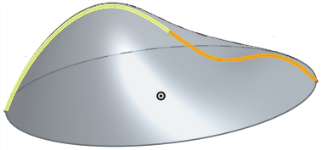
- Check
Show isocurves
to evaluate how the underlying surface is defined.
The untrimmed underlying surface is shown as a mesh to display the iso parametric curves, enabling you to evaluate the quality of the underlying surface.
-
Click
 .
.
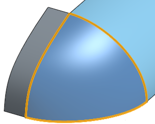
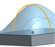
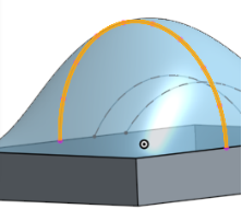
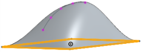
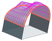
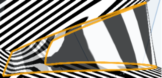
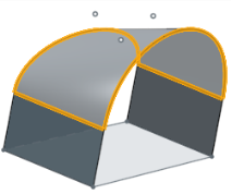
The edges of the surfaces and the two bridging curves are selected as boundaries. A new surface is created:

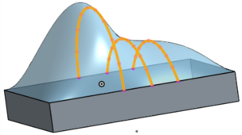
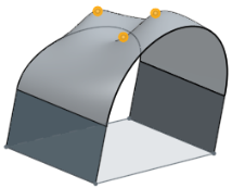
Guide vertices
The Guide vertices are selected to further define the shape of the surface:

Guides with Precise option
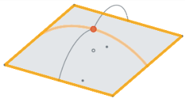
When using the Precise option with guide curves especially, if the curves meet each other, the intersection must be at a point such that the curve and the point are tangent to each other. Also, when using the Precise option, the curves must touch the boundary but not cross the boundary.
Guides that do not intersect
Guides that meet tangentially
Guide that touches one boundary
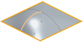
Guide that does not touch a boundary
This scenario can work when Sampled is selected:
But will not succeed when Precise is selected.
Guides that intersect at tangent plane
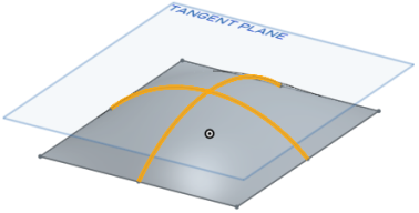
Failure due to lack of tangency
Guides that meet tangent criteria
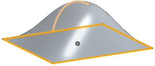
Show isocurves
Show isocurves is selected to display the iso parametric curves, enabling you to evaluate the quality of the underlying surface:
- When selecting edges, you might see red dots; these indicate missing or open curves in the boundary.
- If the operation results in a closed surface (creating a volume), Onshape automatically creates a solid part (if Add is selected). If the creation of a part is an undesired result, use New to keep all surfaces and not create a part.
This lists the collection of surface feature tools. This is not an exhaustive list. Additional Feature tools may be used when modeling surfaces. See Surfacing for additional information.
-
 Thicken - Add depth to a surface. Create a new part or modify an existing one by giving thickness to a surface and converting it to a solid, adding or removing material from an existing part or surface, or intersecting parts in its path.
 -
 Enclose - Create a part by selecting all boundaries surrounding an empty space to form a solid. Use any set of surfaces and solids (including planes and faces) that intersect each other or connect at a boundary to create a volume. Create a new part or modify an existing one by adding, removing, or intersecting parts.
 -
 Fillet - Round sharp interior and exterior edges and define as a standard constant radius, more stylized conic, or variable by selecting Edge fillet. Optionally apply a Full round fillet to create a seamless blend of one or more faces between two opposing sides.
 -
 Face blend - Round sharp connected or disconnected interior and exterior faces to create a seamless blend between the faces or detach the blend to create new faces, defining a radius or constant width. Further define the blend cross section (rolling ball or swept profile), symmetry, control, trim, constraints, and limits.
 -
 Delete face - Remove geometry from a part. Select whether to heal the surrounding faces (by extending until they intersect), cap the void, or leave the void open. This Direct Editing tool is especially convenient if you don't have the parametric history of the part, as is often the case with an imported part.
 -
 Move face - Translate, rotate, or offset one or more selected faces. This Direct Editing tool is especially convenient if you don't have the parametric history of the part, as is often the case with an imported part.
 -
 Replace face - Trim a face or extend a face to a new surface. This Direct Editing tool is especially convenient if you don't have the parametric history of the part, as is often the case with an imported part.
 -
 Offset surface - Create a new surface by offsetting an existing face, surface, or sketch region. Set offset distance to 0 to create a copy in place.
 -
 Boundary surface - Create or add a surface specified by its boundary profiles.
 -
 Fill - Create a surface (or a part from surfaces) by defining boundaries and refine the surface with boundary conditions (instead of requiring the use of reference surfaces).
 -
 Move boundary - Move boundary edges of a surface in order to extend or trim it.
 -
 Ruled surface - Create a new or additional ruled surface from an existing edge or multiple edges of a sketch region.
 -
 Mutual trim - Trim two adjacent surfaces by extending intersections to complete the trim.
 -
 Constrained surface - Create a surface from a selection of points or mesh data within a specified tolerance. Display deviations and optimize for performance or smoothness.
Create a surface (or a part from surfaces) by defining boundaries and refine the surface with boundary conditions (instead of requiring the use of reference surfaces).
- Tap Fill tool.

- Select the Edges, which are boundaries of the fill.
Optionally, define Continuity for each selected edge or curve:
- Tangent
- Create an implicit tangency (normal to the plane of the surface) between the boundaries and the new surface (as if you had a reference surface). Optionally, when selected, the Adjacent faces field is enabled. Pick any face in which underlying geometry is coincident with at least one profile part's curve (the face and edge do not need to intersect or be part of the same part).
- Curvature
- Match the actual curve of the other surface. Optionally, when selected, the Adjacent faces field is enabled. Pick any face in which underlying geometry is coincident with at least one profile part's curve (the face and edge do not need to intersect or be part of the same part).
- Position
- Make edges meet with no tangent or curvature relationship to each other
- Tangent
- Create an implicit tangency (normal to the plane of the surface) between the boundaries and the new surface (as if you had a reference surface). Optionally, when selected, the Adjacent faces field is enabled. Pick any face in which underlying geometry is coincident with at least one profile part's curve (the face and edge do not need to intersect or be part of the same part).
- Select Guide (points, vertices, points on a sketch, or curves) with which to influence the shape. The resulting surface intersects these points. When curves are selected, the surface pushes through the curves and you can select from two types of calculations:
- Sampled - Uses the Sample size to determine the number of vertices along the curves used to calculate the surface. A large sample size may result in the surface following the entire curve. A smaller Sample size may result in some rippling of the surface.
- Precise - uses the exact curve to form the surface. Note that this option requires very carefuflly designed and selected curves.
- Check Show isocurves to evaluate how the underlying surface is defined.
The untrimmed underlying surface is shown as a mesh to display the iso parametric curves, enabling you to evaluate the quality of the underlying surface.
- Tap the checkmark.
The edges of the surfaces and the two bridging curves are selected as boundaries. A new surface is created.

Guide vertices
The Guide vertices are selected to further define the shape of the surface.
Show isocurves
Show isocurves is selected to display the iso parametric curves, enabling you to evaluate the quality of the underlying surface

When selecting edges, you might see red dots; these indicate missing or open curves.
If the operation results in a closed surface (creating a volume), Onshape automatically creates a solid part (if Add is selected). If the creation of a part is an undesired result, use New to keep all surfaces and not create a part.