 Face Blend
![]()
![]()
![]()
Round sharp connected or disconnected interior and exterior faces to create a seamless blend between the faces or detach the blend to create new faces, defining a radius or constant width. Further define the blend cross section (rolling ball or swept profile), symmetry, control, trim, constraints, and limits.
The Face blend feature is a set of surfacing options used in situations where more control is required than a fillet. Where a fillet can be applied only between connected faces and cannot create a new surface, face blend can be applied to both connected and disconnected faces, and can create multiple face blends that can be detached from the faces on which they are applied.
The face blend feature allows you to round sharp connected or disconnected interior and exterior faces to create a seamless blend between the faces or detach the blend to create new faces, defining a radius or constant width. Further define the blend cross section, symmetry, control, trim, constraints, and limits. Face blend is a set of surfacing options used in situations where more control is required than a fillet.
Click the Face blend feature tool on the Part Studio toolbar. Select Side 1 in the graphics area. Select the Side 2 field in the dialog and then select a second side in the graphics area.
Uncheck Propagation to have only the selected edges blended. Keep it enabled to have tangential edges blended. Switch from Tangent to Adjacent to extend the blend to all adjacent faces. Select Custom and enter a maximum angle value to extend the blend to all adjacent faces below the angle value.
Select the cross section type, either Rolling ball or swept profile. Rolling ball is similar to the Fillet feature tool. The rolling ball creates a smooth curved blend between the 2 faces. Alternatively, select Swept profile and then select a Spine. The spine can be a part or sketch edge. This creates a blend that is orthogonal to the spine. Once a cross section type is selected, enter either a Radius or Width for the blend measurement value.
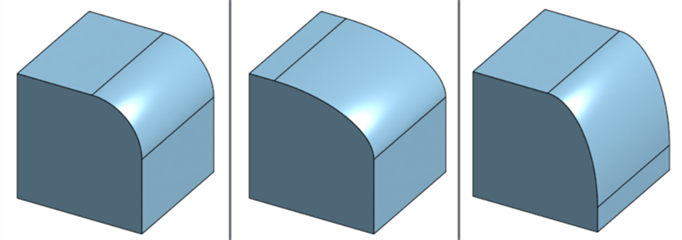
Check Asymmetric and enter a Second radius (if Radius measurement is used) or Ratio (if Width measurement is used) to have a different blend value on one end of the blend. Click the Flip asymmetric arrow to reverse the ends of the asymmetrical blend.
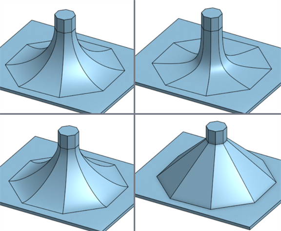
Select a cross sectional control type. Circular creates a rounded slope. Conic creates a conical face with the radius or width measurement value entered, and an optional Rho value to further define the blend slope. Curvature creates a blend that matches the curvature of the surrounding faces with a radius or width measurement value entered and optionally a Magnitude value between 0 and .999 to adjust the tangency. Chamfer creates a linear beveled slope.
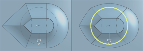
Looking at Trim type options, here is an example with two surfaces, Side 1 on the Front plane and Side 2 on the Top plane. Both surfaces are off center from each other. With the Walls trim type, the blend is created from all edge walls of Side 1 and Side 2. Short creates the shortest possible blend between the Side 1 and Side 2 walls. Long creates the longest possible blend between the Side 1 and Side 2 walls. No trim extends the blend beyond both Side 1 and Side 2 walls.
Check Show isocurves to show a mesh overlay on the surface and evaluate the quality of the underlying surface. Specify the number of isocurves in the Count field.
By default, the blend is attached to the part(s) used for Side 1 and Side 2. Check Detached to separate the blend from the part(s) and create a new surface from the blend in the Parts list. Click the checkmark to accept the new Face blend.
This video explains how the Face blend Constraints and limits are used. In this example, two upper faces are used for Side 1 and two lower faces are used for Side 2.
Check Tangent hold lines and select the tangent edge in the graphics area to clamp the blend under the selected edge. With Tangent hold lines, the blend is clamped symmetrically on both Side 1 and Side 2 faces. To clamp the blend under the selected edge, instead select Inverse tangent edges in the dialog and then select the edge in the graphics area. Again, the blend is clamped symmetrically on both Side 1 and Side 2 faces. Note that you cannot use the Asymmetric option with Tangent hold lines.
Conic hold lines are similar to Tangent hold lines; however, the blend is not symmetrical. Check Conic hold lines, and select the conic edge in the graphics area to clamp the blend under the selected edge. Optionally, select an additional edge to use on the Side 2 face. Notice the blend is clamped above the conic hold line. To invert the clamping, instead select Inverse conic edges in the dialog and then select the edge in the graphics area. Optionally, select an additional edge to use on the Side 2 face. You can also mix between the two options, using a Conic edge for Side 1, and an Inverse conic edge for Side 2, for example.
In the next example, two upper faces are used for Side 1 and one lower face is used for Side 2. In this example, the blend measurement forces the blend to extend beyond the edge of one of the Side 1 faces.
Check Cliff edges and select the face edge in the graphics area to clamp the blend slope to the selected edge. Note that Tangent hold lines, Conic hold lines, and Cliff edges must be edges on Side 1 or Side 2 faces, and cannot be sketch edges.
Check Caps to cap the blend wall edges by selecting a face or plane. In this example, the blend extends beyond the edge of a perpendicular face, with nothing to clamp it from the end of the face to the end of the blend. Click the face perpendicular to the Side 1 faces to cap the blend. Then click the arrow to flip the cap in the other direction. Notice that the blend wall is capped on the opposite side of the selected face.
The next example shows how limits can be used on your blends.
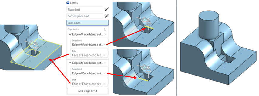
Check Limits. The Plane limit field is automatically selected. Select a plane to limit the blend to the plane. Click the arrow to limit the blend to the opposite side of the plane. Select the Second plane limit field in the dialog and select a second plane in the graphics area. Click the arrow to limit the blend to the opposite side of the second plane. Check Face limits in the dialog and select a face in the graphics area to limit the blend to a face. You can select multiple faces to further limit the blend. To limit the blend to an edge, check Edge limits and select an edge in the graphics area. Click the Side field in the dialog and select the edge face.
In the next example, there are several detached blends between two surfaces.
Check Help point and select a vertex or Mate connector (implicit or explicit) to create only the blend closest to that point. All other face blends are removed.
- Click Face blend (
 ).
).
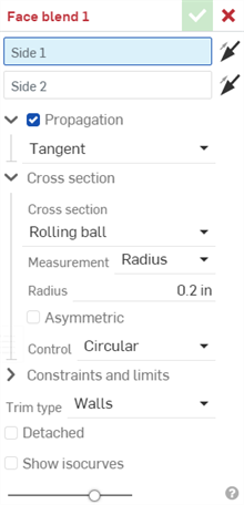
- Select Side 1 in the graphics area. This can be one or more faces from the same part. Optionally, click the arrow to flip side 1, generating the face blend from the opposing side 1 face(s).
- Select Side 2 in the graphics area. This can be one or more faces from the same part. Faces added to side 2 can be from the same part as side 1 or another part. Optionally, click the arrow to flip side 2, generating the face blend from the opposing side 2 face(s).
- Click the Propagation dropdown and check Propagation to have the face blend applied to connected faces using one of the following conditions:
Tangent - The blend extends to all tangent faces.
Adjacent - The blend extends to all adjacent faces.
Custom - The blend extends to all adjacent faces that are less than the maximum angle input.
Tangent propagation does not work when Swept profile is selected.
- Use the Cross section dropdown to expand and select the cross section options. Select a cross section type, either:
Rolling ball - Default option which creates a smooth curved blend between the 2 faces.
Swept profile - Sweeps the profile so the blend edge is orthogonal to the selected spine, a part or sketch edge.
Once a cross section is selected, adjust its measurement, either:
Radius - Specify the radial measurement of the blend.
Width - Specify the distance between the 2 ends of the blend (a constant width).
-
Check Asymmetric and enter a Second radius (if Radius measurement is used) or Ratio (if Width measurement is used) to have a different blend value on one end of the blend. Click the Flip asymmetric arrow to reverse the ends of the asymmetrical blend.
- Select a cross sectional control type, either:
- Circular - Blend is a rounded slope.
- Conic - Blend is a conical face with the radius or width measurement value entered, and an optional Rho value to further define the blend slope.
- Curvature - Blend matches the curvature of the surrounding faces with a radius or width measurement value entered and optionally a Magnitude value between 0 and .999 to adjust the tangency. Turn Zebra stripes on in the small View cube (under the Curvature visualization menu) to see the tangency more clearly.
- Chamfer - Blend is a linear beveled slope.
- Use the Constraints and limits dropdown to expand and select from the following options:
- Tangent hold lines - Select Tangent edges or Inverse tangent edges to clamp the blend under or over the selected edges. When a tangent edge or inverse tangent edge is selected, the blend is clamped symmetrically on both sides.
- Conic hold lines - Select Conic edges and optionally the Inverse conic edges to clamp the blend under or over the selected edges. When a conic edge or inverse conic edge is selected, the blend is not symmetrical. The blend is clamped only above or below the selected edge.
- Cliff edges - If the blend measurement forces the blend to extend beyond the edge of the face, the face is extended by default. Click Cliff edges and select the face edge to clamp the blend slope to the selected edge. This alters the blend angle and can alter the opposing blend's edge to conform to this angle.
- Caps - Caps the blend wall edges by selecting a face or plane. For example, if the blend extends beyond the edge of a perpendicular face, with nothing to clamp it from the end of the face to the end of the blend, click the blend's extended face to cap the blend. Use the Flip cap arrow to flip the direction of the cap. Multiple caps can be added.
- Limits
- Limits the blend in 1 or more of the following ways:
- Plane limit - Select a plane to limit the blend to the plane. Click the Flip first plane arrow to flip the blend to the opposite side of the plane.
- Second plane limit - Select a second plane to limit the blend to an additional plane. Click the Flip second plane arrow to flip the blend to the opposite side of the second plane.
- Face limits - Select a face to limit the blend to a face.
- Edge limits - Select an edge limit to halt the blend at a specified edge. Click the selections dropdown and enter an Edge limit and Side (the side of the edge where the blend is kept). Multiple edge limits can be added.
- Help point - If multiple face blends are created, select a vertex or Mate connector (implicit or explicit) to create only the blend closest to that point. All other face blends are removed.
Due to the tangent edge or inverse tangent edge creating a symmetrical clamp on both sides of the blend, you cannot use the Asymmetric option with Tangent hold lines.
Tangent hold lines, Conic hold lines, and Cliff edges must be edges on Side 1 or Side 2 faces. You cannot use sketch edges. Split the face to create an edge that can be used.
- Select a Trim type, either:
- Wall - Creates the blend from the edge walls of both Side 1 and Side 2.
- Short - Creates the shortest possible blend between Side 1 and Side 2 walls.
- Long - Creates the longest possible blend between Side 1 and Side 2 walls.
- No trim - The blend is not trimmed, and instead goes beyond the Side 1 and Side 2 walls.
- By default, the blend is attached to the part(s) used for Side 1 and Side 2. Check Detached to separate the blend from the part(s) and create a new surface from the blend in the Parts list.
- Check Show isocurves to show a mesh overlay on the surface and evaluate the quality of the underlying surface. Specify the number of isocurves in the Count field.
-
Click
 .
.
Tips
-
Side 1 faces do not need to be connected to Side 2 faces.
-
Click any of the arrows in the graphics area to flip the corresponding Face blend option (Side 1, Side 2, Plane limit, Second plane limit).
-
Long and No trim Trim types can be used for a support surface or surface that is manually trimmed after it is created (detached).
-
Onshape remembers the selection for Cross section, measurement, Constraints and limits, and Trim type, opening the dialog with the last selected option in subsequent operations.
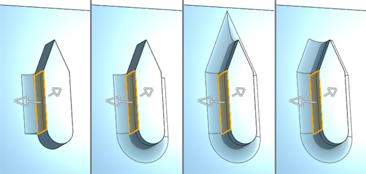
Propagation examples from left to right: No propagation (propagation unchecked), tangent propagation, adjacent propagation, and custom propagation with an angle value of 100 degrees:
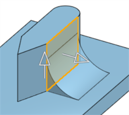
Rolling ball example:
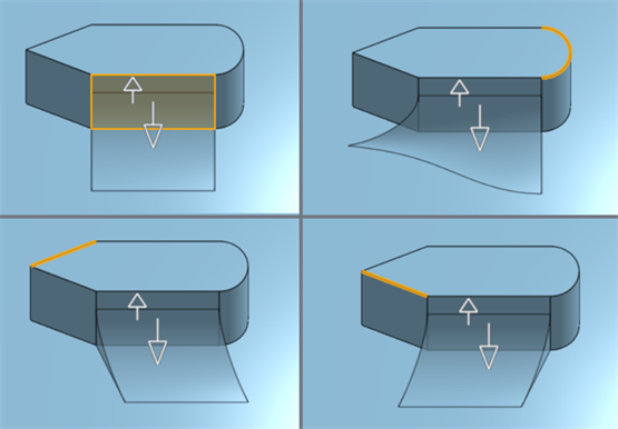
Swept profile examples where different edges of the part (highlighted in orange) are used for the spine. When the straight edge at the top of the blend is selected for the spine, the result is similar to the Rolling ball option (top left). Selecting any other edge for the spine alters the shape of the blend (shown in the other 3 images):
The example below left shows a Rolling ball cross section. The example below right shows a Swept profile cross section with the circle sketch selected for the spine. This spine influences the angle and edges of the blend, orthogonal to the circle:
Non-asymmetric blend (left), asymmetric blend (middle), and asymmetric blend after it is flipped (right):
Clockwise from top left: Circular, Conic (Rho = 0.7), Chamfer, and Curvature (magnitude = 0.3):
Tangent hold lines
The following 2 images show the 2 upper Side 1 faces (shown below in orange) blended with the 2 lower Side 2 faces (shown below in yellow) without any tangent hold lines:
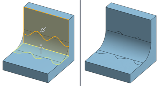
When the tangent edge is selected (shown below in yellow), the blend is clamped below the edge, and this clamping is symmetrical:
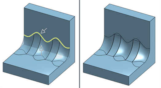
If the same edge is instead selected as an inverse tangent edge, the blend created is clamped above the top edge. and this clamping is symmetrical:
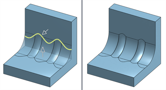
Conic hold lines
The following is an example of Tangent hold lines with the tangent edge shown in yellow. The blend clamping is symmetrical:

The following is an example of the Conic hold lines, where the same edge is selected for the Conic edge. This does not result in symmetrical clamping. Instead, the blend is clamped only below the selected conic edge:
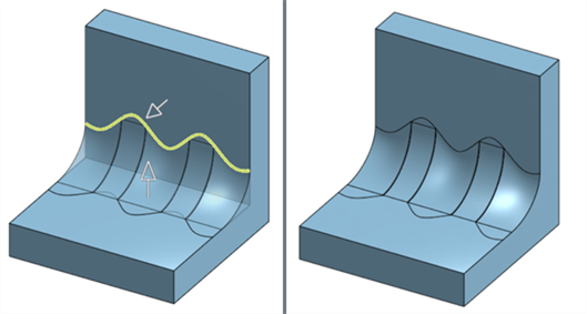
If the same edge is instead selected as an inverse conic edge, the blend created is clamped only above the top edge:
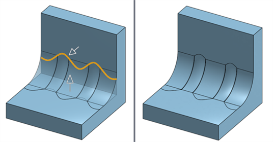
Cliff edges
Without cliff edges, the blend extends beyond the edge of the top face (marked by the red arrows in the left image). With cliff edges enabled, the blend is clamped to the selected edge (shown in yellow in the right image below). This also has the effect of slightly curving the blend along the bottom edge (marked by the red arrow in the right image):
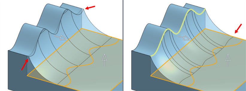
Cliff edges disabled (left); Cliff edges enabled (right).
Caps
Blending 2 faces generates an error when trying to attach the blend:
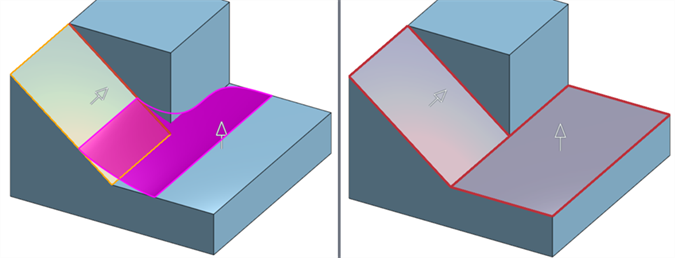
Trim type: Walls (left); Trim type: Short (right).
Selecting Detached resolves the error. However, the blend is a new surface that is not attached to the part:
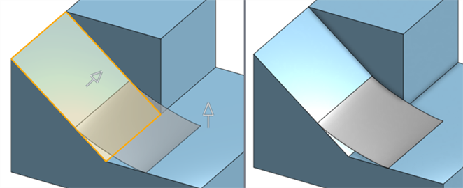
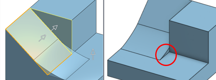
To resolve the error and attach the blend to the part, select Caps and add the perpendicular face as the blend Cap (outlined in yellow in the image below left). This caps the blend extension (as outlined in red in the image below right):
Limits
Plane limits
Plane limit examples, from left to right: Selecting Plane 1 as the Plane limit, adding Plane 2 as the Second Plane limit, flipping Plane 1 in the opposite direction, and flipping both Planes to reverse both their directions:

Face limits
The following example shows Side 1 (orange) and Side 2 (yellow) without face limits applied:
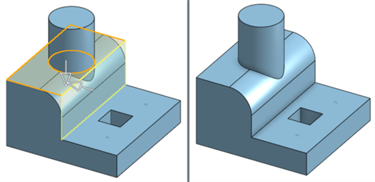
The same example shows the cylinder face applied as a face limit. This limits the blend from the outer wall edge to the edge of the cylinder face, resulting in the blend removed from the middle:
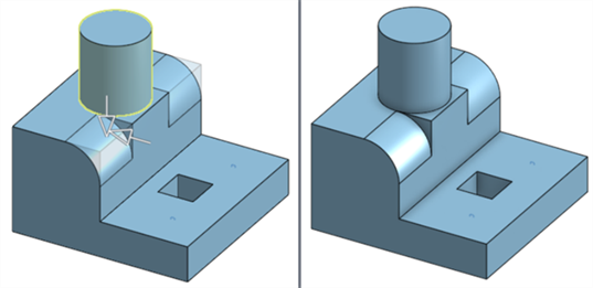
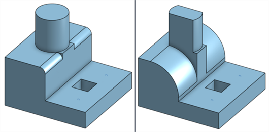
If the cross section radius or width is reduced, the blend wraps around the cylinder's edge (below left). If the cross section radius or width is increased, the blend instead removes a portion of the cylinder from the part (below right).
Edge limits
The following example shows Side 1 (orange) and Side 2 (yellow) without edge limits applied:
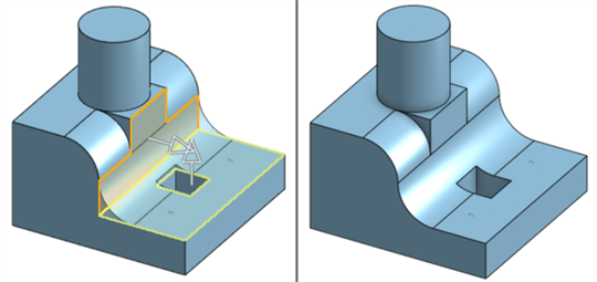
The same example shows 2 Edge limits applied. Both limits use the same Side; however, each limit uses a different Edge limit from the same side. This limits the blend from the outer wall edge to the limit edge on each side, removing the middle section between the 2 Edge limits:
Help point
If multiple blends are created, use the Help point to select a vertex or Mate connector to indicate which blend you want to keep and which to remove. The blend closest to the point is kept. For example:
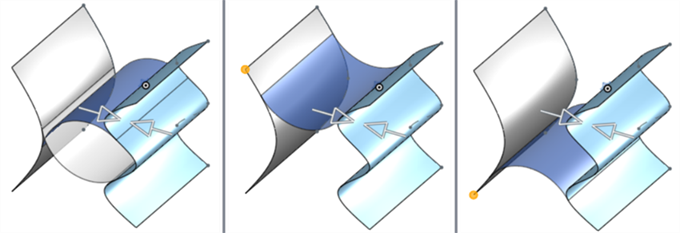
Two detached face blend surfaces are created between the left and right surfaces (shown in the left image). Selecting the top left vertex of the left surface (shown in orange in the middle image) keeps the top surface and removes the bottom. Selecting the bottom left vertex instead keeps the bottom face blend (shown in the right image).
Trim type examples, from left to right: Walls, Short, Long, and No trim. For each image, Side 1 is shown in orange and Side 2 is shown in yellow:

With an attached blend (default), the blend is attached to the part (Part 1 in the left image below). With a detached blend, the blend is separated from the part and becomes a new surface (Surface 1 in the right image below):
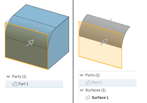
Detaching a blend is useful when you have self-intersecting surfaces that generate an error. In the left image below, the 2 face blends between 2 surfaces are self-intersecting, which creates an error. In the right image below, the face blends are detached. This creates 2 new surfaces from the 2 face blends and resolves the error:
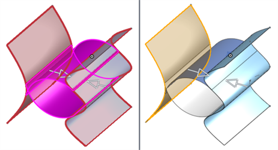
Two examples where Show isocurves is enabled with Count: 10 (shown left) and Count: 4 (shown right):

This lists the collection of surface feature tools. This is not an exhaustive list. Additional Feature tools may be used when modeling surfaces. See Surfacing for additional information.
-
 Thicken - Add depth to a surface. Create a new part or modify an existing one by giving thickness to a surface and converting it to a solid, adding or removing material from an existing part or surface, or intersecting parts in its path.
 -
 Enclose - Create a part by selecting all boundaries surrounding an empty space to form a solid. Use any set of surfaces and solids (including planes and faces) that intersect each other or connect at a boundary to create a volume. Create a new part or modify an existing one by adding, removing, or intersecting parts.
 -
 Fillet - Round sharp interior and exterior edges and define as a standard constant radius, more stylized conic, or variable by selecting Edge fillet. Optionally apply a Full round fillet to create a seamless blend of one or more faces between two opposing sides.
 -
 Face blend - Round sharp connected or disconnected interior and exterior faces to create a seamless blend between the faces or detach the blend to create new faces, defining a radius or constant width. Further define the blend cross section (rolling ball or swept profile), symmetry, control, trim, constraints, and limits.
 -
 Delete face - Remove geometry from a part. Select whether to heal the surrounding faces (by extending until they intersect), cap the void, or leave the void open. This Direct Editing tool is especially convenient if you don't have the parametric history of the part, as is often the case with an imported part.
 -
 Move face - Translate, rotate, or offset one or more selected faces. This Direct Editing tool is especially convenient if you don't have the parametric history of the part, as is often the case with an imported part.
 -
 Replace face - Trim a face or extend a face to a new surface. This Direct Editing tool is especially convenient if you don't have the parametric history of the part, as is often the case with an imported part.
 -
 Offset surface - Create a new surface by offsetting an existing face, surface, or sketch region. Set offset distance to 0 to create a copy in place.
 -
 Boundary surface - Create or add a surface specified by its boundary profiles.
 -
 Fill - Create a surface (or a part from surfaces) by defining boundaries and refine the surface with boundary conditions (instead of requiring the use of reference surfaces).
 -
 Move boundary - Move boundary edges of a surface in order to extend or trim it.
 -
 Ruled surface - Create a new or additional ruled surface from an existing edge or multiple edges of a sketch region.
 -
 Mutual trim - Trim two adjacent surfaces by extending intersections to complete the trim.
 -
 Constrained surface - Create a surface from a selection of points or mesh data within a specified tolerance. Display deviations and optimize for performance or smoothness.
Round sharp connected or disconnected interior and exterior faces to create a seamless blend between the faces or detach the blend to create new faces, defining a radius or constant width. Further define the blend cross section (rolling ball or swept profile), symmetry, control, trim, constraints, and limits.
The Face blend feature is a set of surfacing options used in situations where more control is required than a fillet. Where a fillet can be applied only between connected faces and cannot create a new surface, face blend can be applied to both connected and disconnected faces, and can create multiple face blends that can be detached from the faces on which they are applied.
- Tap the Face blend tool (
 ).
).


Face blend dialog on iOS (left) and Android (right).
- Select Side 1 in the graphics area. This can be one or more faces from the same part. Optionally, tap the arrow to flip side 1, generating the face blend from the opposing side 1 face(s).
- Select Side 2 in the graphics area. This can be one or more faces from the same part. Faces added to side 2 can be from the same part as side 1 or another part. Optionally, tap the arrow to flip side 2, generating the face blend from the opposing side 2 face(s).
- Tap the Propagation dropdown and check Propagation to have the face blend applied to connected faces using one of the following conditions:
Tangent - The blend extends to all tangent faces.
Adjacent - The blend extends to all adjacent faces.
Custom - The blend extends to all adjacent faces that are less than the maximum angle input.
Tangent propagation does not work when Swept profile is selected.
- Use the Cross section dropdown to expand and select the cross section options. Select a cross section type, either:
Rolling ball - Default option which creates a smooth curved blend between the 2 faces.
Swept profile - Sweeps the profile so the blend edge is orthogonal to the selected spine, a part or sketch edge.
Once a cross section is selected, adjust its measurement, either:
Radius - Specify the radial measurement of the blend.
Width - Specify the distance between the 2 ends of the blend (a constant width).
-
Toggle Asymmetric on and enter a Second radius (if Radius measurement is used) or Ratio (if Width measurement is used) to have a different blend value on one end of the blend. Tap the Flip asymmetric arrow to reverse the ends of the asymmetrical blend.
- Select a cross sectional control type, either:
- Circular - Blend is a rounded slope
- Conic - Blend is a conical face with the radius or width measurement value entered, and an optional Rho value to further define the blend slope.
- Curvature - Blend matches the curvature of the surrounding faces with a radius or width measurement value entered and optionally a Magnitude value between 0 and .999 to adjust the tangency. Turn Zebra stripes on in the small View cube (under the Curvature visualization menu) to see the tangency more clearly.
- Chamfer - Blend is a linear beveled slope.
- Use the Constraints and limits dropdown to expand and select from the following options:
- Tangent hold lines - Select Tangent edges or Inverse tangent edges to clamp the blend under or over the selected edges. When a tangent edge or inverse tangent edge is selected, the blend is clamped symmetrically on both sides.
- Conic hold lines - Select Conic edges and optionally the Inverse conic edges to clamp the blend under or over the selected edges. When a conic edge or inverse conic edge is selected, the blend is not symmetrical. The blend is clamped only above or below the selected edge.
- Cliff edges - If the blend measurement forces the blend to extend beyond the edge of the face, the face is extended by default. Click Cliff edges and select the face edge to clamp the blend slope to the selected edge. This alters the blend angle and can alter the opposing blend's edge to conform to this angle.
- Caps - Caps the blend wall edges by selecting a face or plane. For example, if the blend extends beyond the edge of a perpendicular face, with nothing to clamp it from the end of the face to the end of the blend, tap the blend's extended face to cap the blend. Use the Flip cap arrow to flip the direction of the cap. Multiple caps can be added.
- Limits
- Limits the blend in 1 or more of the following ways:
- Plane limit - Select a plane to limit the blend to the plane. Tap the Flip first plane arrow to flip the blend to the opposite side of the plane.
- Second plane limit - Select a second plane to limit the blend to an additional plane. Tap the Flip second plane arrow to flip the blend to the opposite side of the second plane.
- Face limits - Select a face to limit the blend to a face.
- Edge limits - Select an edge limit to halt the blend at a specified edge. Tap the selections dropdown and enter an Edge limit and Side (the side of the edge where the blend is kept). Multiple edge limits can be added.
- Help point - If multiple face blends are created, select a vertex or Mate connector (implicit or explicit) to create only the blend closest to that point. All other face blends are removed.
Due to the tangent edge or inverse tangent edge creating a symmetrical clamp on both sides of the blend, you cannot use the Asymmetric option with Tangent hold lines.
Tangent hold lines, Conic hold lines, and Cliff edges must be edges on Side 1 or Side 2 faces. You cannot use sketch edges. Split the face to create an edge that can be used.
- Select a Trim type, either:
- Wall - Creates the blend from the edge walls of both Side 1 and Side 2.
- Short - Creates the shortest possible blend between Side 1 and Side 2 walls.
- Long - Creates the longest possible blend between Side 1 and Side 2 walls.
- No trim - The blend is not trimmed, and instead goes beyond the Side 1 and Side 2 walls.
- By default, the blend is attached to the part(s) used for Side 1 and Side 2. Toggle Detached to separate the blend from the part(s) and create a new surface from the blend in the Parts list.
- Toggle Show isocurves to show a mesh overlay on the surface and evaluate the quality of the underlying surface. Specify the number of isocurves in the Count field.
-
Click
 .
.
Show isocurves is not fully supported on iOS and Android platforms
Tips
-
Side 1 faces do not need to be connected to Side 2 faces.
-
Tap any of the arrows in the graphics area to flip the corresponding Face blend option (Side 1, Side 2, Plane limit, Second plane limit).
-
Long and No trim Trim types can be used for a support surface or surface that is manually trimmed after it is created (detached).
-
Onshape remembers the selection for Cross section, measurement, Constraints and limits, and Trim type, opening the dialog with the last selected option in subsequent operations.
-
For additional examples of Face blend options, refer to the Face blend: Desktop section.