![]()
![]()
![]()
Modifica una curva esistente o crea una nuova curva selezionando entità o curve di schizzo per applicare un'approssimazione semplificata, elevare il grado, riposizionare i vertici della curva di controllo e/o renderla piana in qualsiasi piano 2D.
Modifica curva consente di modificare la curva mantenendo la sua associazione con tutte le funzioni a valle che si basano su di essa. Questo aiuta a correggere eventuali superfici risultanti da curve errate più in alto nella catena di modellazione. Ad esempio, se un loft presenta una superficie non valida, modificando le curve originali utilizzate come base per il loft si ottiene una superficie migliore.
Utilizza la funzione Modifica curva per:
-
Migliorare la geometria della curva importata per renderla uniforme, levigata, ricostruita, riparametrizzata e riapprossimata.
-
Modificare la forma di una curva esistente tramite i relativi punti di controllo.
-
Posizionare il punto di controllo di una curva in riferimento ad un'altra geometria. Ad esempio, se si dispone di diverse configurazioni di dimensioni alternative di una barra trasversale e si desidera che la curva di una parte diversa aggiorni il suo allineamento alla barra trasversale.
-
Elevare il grado della curva per adattarlo al grado desiderato, migliorare la connettività o ottenere un controllo più preciso sulla forma della curva.
-
Correggere una torsione/un cambio di direzione indesiderati nella curva. La curva e i relativi punti di controllo sono spostati su un piano o mate connector selezionato per raddrizzarlo (renderlo piano).
Le curve sono comunemente utilizzate per fornire la base per geometrie 3D complesse, sia che servano come curve guida per loft e superfici di bordo complessi, sia come percorsi per sweep. In alcuni casi può essere necessario regolare queste curve per adattarle all'intento progettuale desiderato. In questi casi, la funzione Modifica curva di Onshape consente di modificare la curva mantenendo tutte le associazioni con le funzioni a valle che dipendono dalla curva. Ad esempio, una curva può presentare una torsione indesiderata che influisce sulla forma di una funzione Loft. Modificando la curva per attenuare la torsione si ottiene un loft più fluido.
La funzione Modifica curva offre diverse opzioni per ricostruire e rimodellare curve e per lavorare con curve provenienti da varie fonti native o importate.
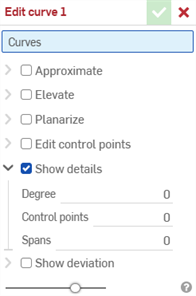
La funzione Modifica curva consente inoltre di mostrare o nascondere i valori di sola lettura della curva per il grado, il numero di punti di controllo e il numero di segmenti annodati.
Seleziona Approssima per riapprossimare la curva. Questo ricostruisce la curva secondo una nuova specifica matematica. Imposta il grado di destinazione, il numero massimo di punti di controllo e la tolleranza. Seleziona Conserva derivata di inizio e Conserva derivata di fine per preservare la tangenza della curva a entrambe le estremità della curva.
Seleziona Eleva per fornire un nuovo grado di destinazione per la curva. Questa opzione eleva la curva a questo nuovo livello più alto, aumentando così il numero di punti di controllo, e questo può offrire un controllo più preciso della forma della curva.
Seleziona Rendi piana per proiettare i punti di controllo della curva dalla loro posizione corrente su un piano di riferimento selezionato. Esistono numerose opzioni per determinare il piano su cui Onshape proietta i punti di controllo. L'opzione Adatta proietta i punti di controllo su un piano che corrisponde maggiormente al percorso della curva, utilizzando la media di tutte le posizioni dei punti di controllo. Seleziona Blocca estremità per bloccare le estremità della curva nelle rispettive posizioni originali. I piani YZ, XZ e XY proiettano i punti di controllo sul rispettivo piano. La funzione personalizzata progetta i punti di controllo su un piano selezionato o sul piano fornito da un mate connector. Seleziona l'icona Mate connector per attivare la selezione di mate connector impliciti o espliciti.
Seleziona Modifica punti di controllo per modificare la posizione e il peso dei singoli punti di controllo sulla curva selezionata. L'indice iniziale del punto di controllo è 0, corrispondente al primo punto di controllo lungo la curva. Seleziona punti di controllo aggiuntivi inserendo il relativo numero di indice o selezionando il punto di controllo appropriato nell'area grafica. Una volta selezionato un punto di controllo, fai clic su Aggiungi sovrascrittura punto per immettere manualmente i valori di offset e peso oppure regola la posizione utilizzando il manipolatore triade nell'area grafica. Per impostazione predefinita, questi offset sono relativi alla posizione del punto di controllo originale, ma è possibile spostarli da un punto specifico fornendo un riferimento opzionale. Spessore determina lo spessore del punto di controllo rispetto alla curva. Più elevato è lo spessore, più la curva è disegnata verso il punto di controllo. Lo spessore moltiplica l'influenza del punto sulla curva per il valore immesso.
L'ordine delle operazioni della finestra di dialogo è gerarchico dall'alto verso il basso (da Approssima a Eleva, Rendi piana e infine Modifica punti di controllo). Se desideri modificare questo ordine delle operazioni, crea più funzioni di modifica della curva che modificano in sequenza l'ordine in base alle tue esigenze. Ad esempio, crea una funzione Modifica curva che modifichi i punti di controllo della curva e una seconda funzione Modifica curva per rendere piana la stessa curva.
Puoi utilizzare Approssima o Eleva per garantire che il numero di punti di controllo su ciascuna curva sia identico, aiutando ad allineare e a rendere fluida la superficie di un loft.
Con almeno un'entità dello schizzo lineare o una curva disponibile nell'area grafica:
- Fai clic sulla funzione Modifica curva (
 ) nella barra degli strumenti.
-
Seleziona una o più entità dello schizzo lineare e/o curve che non si intersecano nell'area grafica. Le entità o le curve dello schizzo devono seguire un percorso continuo e, se sono selezionate più curve, devono essere riapprossimate (seleziona Approssima di seguito), che genera una nuova curva.
- Seleziona Approssima per aprire opzioni che consentono di riapprossimare la curva. La curva originale è visualizzata in arancione e la nuova curva approssimata in magenta. Approssima tenta di mantenere la geometria della curva, ma ciò non è sempre garantito.
Grado destinazione: inserisci il grado della curva destinazione per la curva selezionata.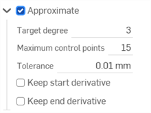
- Numero massimo di punti di controllo: inserisci il numero massimo di punti di controllo consentiti per la curva selezionata.
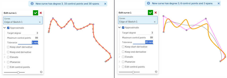
- Tolleranza: la tolleranza della curva selezionata, come misura della lunghezza. Inserisci il valore della tolleranza.
- Conserva derivata di inizio: seleziona questa opzione per mantenere la tangenza all'inizio della curva selezionata.
- Conserva derivata di fine: seleziona questa opzione per mantenere la tangenza alla fine della curva selezionata.
- Seleziona Eleva per aprire l'opzione Grado destinazione. Se necessario, inserisci un grado di curva destinazione più elevato per la curva selezionata. Questo risulta utile per raggiungere il grado desiderato, migliorare la connettività o ottenere un controllo più preciso sulla forma della curva. La geometria della curva è conservata.

- Seleziona Rendi piana per accedere a opzioni che consentono di raddrizzare la curva lungo un piano di riferimento. Rendere piana la curva proietta le curve di controllo dalla loro posizione corrente al piano di riferimento selezionato:

Le opzioni del piano di riferimento sono:
Adatta: proietta la curva lungo il piano che corrisponde maggiormente al percorso della curva (utilizzando la media di tutte le posizioni del punto di controllo).
Blocca estremità: verifica che i punti finali della curva siano fissi e non si muovano. Questo è utile per preservare la continuità con la geometria associata.
Piano YZ: proietta la curva lungo il piano YZ (normale all'asse X).
Piano XZ: proietta la curva lungo il piano XZ (normale all'asse Y).
Piano XY: proietta la curva lungo il piano XY (normale all'asse Z).
Personalizzato: proietta la curva lungo un piano personalizzato o gli assi XY di un mate connector esplicito o implicito (normale al suo asse Z).
- Seleziona Modifica punti di controllo per aprire le opzioni per aggiungere un riferimento, quindi modifica la posizione e lo spessore dei singoli punti di controllo sulla curva selezionata:
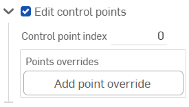
Una volta attivata l'opzione Modifica punti di controllo, il manipolatore triade è visibile nell'area grafica e la sua origine è posizionata sul primo punto di controllo (Indice del punto di controllo 0).
Questo campo dell'Indice punto di controllo è l'indice/l'ID di primo livello di un punto sulla curva e inizia da 0. È possibile selezionare ciascun punto di controllo numericamente inserendo il numero di indice in questo campo. Durante questa operazione il manipolatore triade si sposta sul punto di controllo corrispondente nell'area grafica.
Il manipolatore triade regola:
la traslazione su 3 assi
la traslazione su 3 piani.
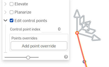
Facendo clic sul pulsante Aggiungi sovrascrittura punto o regolando il manipolatore triade si aggiunge un'opzione di sovrascrittura per il punto attualmente selezionato:
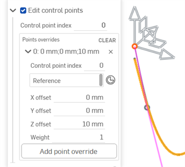
Regolando di 10 mm il manipolatore dell'asse Z si aprono le opzioni per il punto di controllo corrente (indice 0 nell'immagine sopra).
È possibile aggiungere impostazioni di sovrascrittura singolarmente per ogni punto di controllo sulla curva. Fai clic sul pulsante Aggiungi sostituzione punto per aggiungere impostazioni di sovrascrittura personalizzate a un punto aggiuntivo. A ogni punto può essere applicato un solo set di impostazioni di sovrascrittura.
È possibile sovrascrivere espandi/comprimi ogni riga/punto di controllo premendo il simbolo dell'accento circonflesso rivolto a destra (
 ) che si trova a sinistra della riga. Ciascuna delle sovrascritture del punto elenca il numero di indice seguito dai valori di offset X/Y/Z. Fai clic sulla x a destra di ogni riga per cancellare le sovrascritture di tale punto. Fai clic su CANCELLA nell'angolo superiore destro della tabella per cancellare tutte le impostazioni di sovrascrittura per tutte le righe/tutti i punti di controllo.
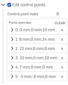
Se necessario, modifica ciascuna delle seguenti opzioni di sovrascrittura del punto di controllo:
- Indice punto di controllo: è l'indice del punto di controllo che si sovrascrive. Seleziona l'indice/l'ID di un punto sulla curva. L'indicizzazione inizia da 0.
Cambiare i numeri di indice dei punti di controllo a questo livello applica tutte le impostazioni correnti di sovrascrittura dei punti a tale punto di controllo. In questo modo è possibile trasferire istantaneamente le impostazioni di sovrascrittura da un punto di controllo a un altro.
Modifica le seguenti impostazioni di sovrascrittura per ogni punto di controllo sulla curva:
- Riferimento: il riferimento predefinito è la posizione del punto di controllo invariata (punto di origine del manipolatore triade). Seleziona un vertice, un punto di schizzo o un mate connector esplicito o implicito per rendere i valori di offset X/Y/Zdel punto corrente relativi a questo punto.
Per creare un mate connector implicito durante la modifica del punto di controllo, fai clic sull'icona Seleziona l'icona mate connector (
 ), quindi fai clic su una posizione nel modello per creare il mate connector. Questo sarà ora utilizzato come punto di riferimento.
 - Offset X/Y/Z: visualizza la posizione corrente del punto di controllo, poiché è sottoposta a offset rispetto al suo riferimento. Se necessario, inserisci i valori numerici di offset in ogni campo.
- Spessore: determina lo spessore del punto di controllo rispetto alla curva. Valori di spessore più elevati 'avvicinano' la curva al punto di controllo. Inserisci un valore di spessore per moltiplicare l'influenza del punto sulla curva di tale quantità.
- Riferimento: il riferimento predefinito è la posizione del punto di controllo invariata (punto di origine del manipolatore triade). Seleziona un vertice, un punto di schizzo o un mate connector esplicito o implicito per rendere i valori di offset X/Y/Zdel punto corrente relativi a questo punto.
- Aggiungi sovrascrittura punto: aggiunge una nuova sovrascrittura punto nella tabella con l'indice correntemente selezionato o il primo indice inutilizzato nell'array dopo l'indice corrente, se l'indice corrente è già utilizzato.
- (Facoltativo) Per impostazione predefinita l'opzione Mostra dettagli è abilitata e fornisce una visualizzazione di sola lettura del valore del grado, del numero di punti di controllo e del numero di Segmenti annodati. Deseleziona l'opzione per nascondere questi dettagli.
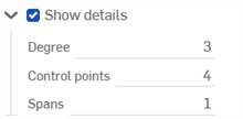
- (Facoltativo) Se la curva è stata riapprossimata, è possibile attivare la casella di controllo Mostra deviazione per visualizzare la deviazione massima tra la curva originale e la curva riapprossimata.

- Fai clic sul segno di spunta (
 ) per accettare la funzione di modifica della curva.
-
La curva originale prima (a sinistra) e dopo l'uso di Approssima (a destra):

-
Creazione di una nuova curva da 2 entità di schizzo tangenziali (a sinistra); dopo aver usato Approssima, sono unite in un'unica curva (a destra). Le entità di schizzo originali rimangono e possono ancora essere utilizzate per altri scopi.

-
Usare l'opzione Tolleranza per smussare una curva:
-
Elevare per corrispondere a un grado di destinazione:
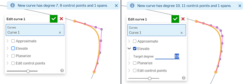
Senza alcuna elevazione (a sinistra) e con elevazione pari al grado di destinazione 10 (a destra)
-
Usare Rendi piana per raddrizzare una curva lungo un piano:
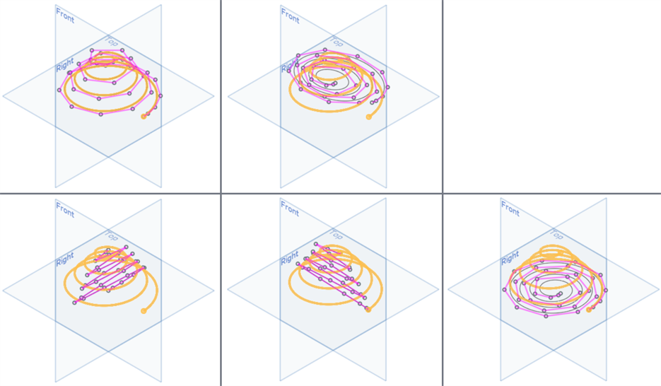
In alto: funzione Rendi piana deselezionata (a sinistra), Adatta (a destra); In basso da sinistra a destra: piano YZ, piano XZ, piano XY
-
Rendere piana un'elica trasformandola in una spirale
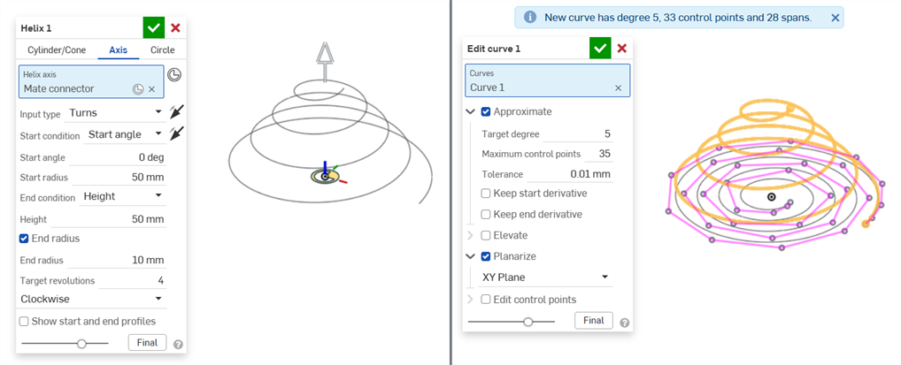
Funzione Elica (a sinistra) e dopo aver reso piana l'elica trasformandola in una spirale usando Modifica curva > Rendi piana (a destra)
-
Applica Rendi piana usando l'opzione Personalizzato e selezionando un mate connector come base per il piano:

Opzione Rendi piana deselezionata (a sinistra) e selezionata (a destra). È selezionata l'opzione Personalizzato e si utilizza un mate connector per il piano personalizzato.
La stessa curva di cui sopra quando è resa piana utilizzando il piano del mate connector personalizzato, mostrata nel contesto degli altri piani:
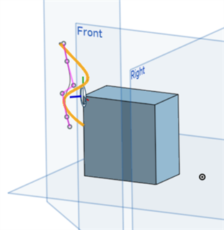
-
Modifica i punti di controllo lungo una curva per regolarne la forma:
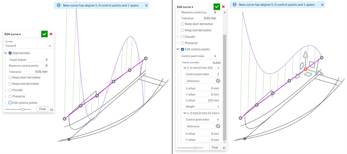
La curva originale senza punti modificati (a sinistra) e con i punti 2 e 4 modificati per creare una curva più liscia (a destra)
-
Modificare un punto di controllo con riferimento alla geometria esistente (esterna alla curva). Utilizzando questo metodo, se la geometria di riferimento cambia, la curva segue tale geometria. Ad esempio, se hai diverse dimensioni per la geometria di riferimento e le imposti come configurazioni, la curva seguirà sempre la geometria, indipendentemente dalla configurazione selezionata.
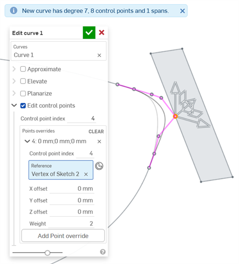
Dopo aver importato il CAD, potresti avere una curva errata. Questo problema può aggravarsi se hai eseguito molto lavoro di modellazione utilizzando la curva errata, accorgendotene solo in una fase successiva del processo di progettazione.
Ecco un esempio di dati CAD importati (l'importazione è costituita da curve utilizzate per una barca). Utilizzando lo strumento di analisi delle curve/superfici, è possibile riscontrare problemi nella seguente curva:
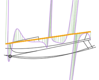
Man mano che sono create superfici da questa curva, i dati della curva mal costruita sono trasmessi a valle nel processo di progettazione. Modificando la curva (prima immagine qui di seguito) si ottiene una curva più regolare (seconda immagine). È possibile modificare la curva direttamente dopo il processo di importazione, e tutte le funzioni a valle che si basano sulla curva sono aggiornate automaticamente:
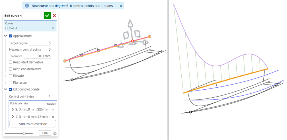
Approssimazione della curva al grado destinazione: 5; numero massimo di punti di controllo: 6, quindi modificare i punti di controllo per creare una curva uniforme.
Quanto segue mostra la differenza di qualità della superficie di bordo risultante generata come risultato dell'uso a valle delle funzioni originate dalla curva precedente:
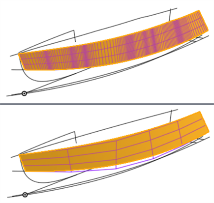
Una superficie di bordo creata dalla curva che mostra una superficie problematica (in alto) e una superficie di qualità migliore dopo la modifica della curva (in basso). Avere meno punti di controllo nelle curve significa una superficie più liscia.
-
Esiste un ordine gerarchico o operazioni gerarchiche (ordine di dipendenza) quando si applicano le opzioni Modifica curva a una curva. Approssima è applicato prima, quindi Eleva, quindi Rendi piana e infine Modifica punti di controllo. Se desideri usare Modifica punti di controllo della curva e poi Rendi piana come passaggio successivo, puoi farlo creando due funzioni Modifica curva, una dopo l'altra. Nella prima funzione Modifica curva modifica i punti di controllo della curva. Quindi, nella seconda funzione Modifica curva, rendi piana la curva.
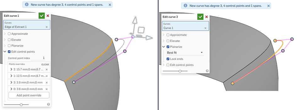
Modificare i punti di controllo della curva nella prima funzione Modifica curva (a sinistra) e renderla piana nella seconda funzione Modifica curva (destra) per invertire l'ordine delle operazioni eseguite sulla curva
-
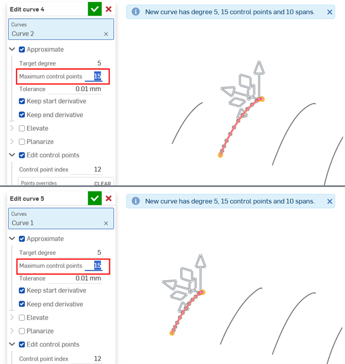
Quando modifichi più curve come base per un loft (che alla fine crea una superficie), assicurati che vi sia un numero uguale di punti di controllo su ciascuna curva. Ciò garantisce il parallelismo tra i punti su ciascuna curva, creando un loft ben definito.
Modifica una curva esistente o crea una nuova curva selezionando entità o curve di schizzo per applicare un'approssimazione semplificata, elevare il grado, riposizionare i vertici della curva di controllo e/o renderla piana in qualsiasi piano 2D.
Passaggi
Con almeno un'entità dello schizzo lineare o una curva disponibile nell'area grafica:
-
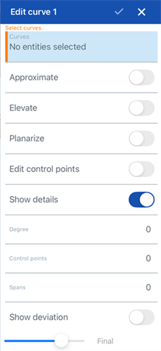
Tocca l'icona dello strumento Modifica curva (
 ).
).
-
Seleziona una o più entità dello schizzo lineare e/o curve che non si intersecano nell'area grafica. Le entità o le curve dello schizzo devono seguire un percorso continuo e, se sono selezionate più curve, devono essere riapprossimate (seleziona Approssima di seguito), che genera una nuova curva.
-
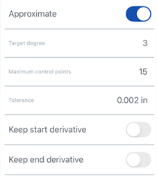
Tocca l'interruttore accanto ad Approssima per aprire opzioni che consentono di riapprossimare la curva. La curva originale è visualizzata in arancione e la nuova curva approssimata in magenta. Approssima tenta di mantenere la geometria della curva, ma ciò non è sempre garantito.
-
Grado destinazione: inserisci il grado della curva destinazione per la curva selezionata.
-
Numero massimo di punti di controllo: inserisci il numero massimo di punti di controllo consentiti per la curva selezionata.
-
Tolleranza: la tolleranza della curva selezionata, come misura della lunghezza. Inserisci il valore della tolleranza.
-
Conserva derivata di inizio: seleziona questa opzione per mantenere la tangenza all'inizio della curva selezionata.
-
Conserva derivata di fine: seleziona questa opzione per mantenere la tangenza alla fine della curva selezionata.
-
-
Tocca l'interruttore accanto a Eleva per aprire l'opzione Grado destinazione. Se necessario, inserisci un grado di curva destinazione più elevato per la curva selezionata. Questo risulta utile per raggiungere il grado desiderato, migliorare la connettività o ottenere un controllo più preciso sulla forma della curva. La geometria della curva è conservata.
-
Tocca l'interruttore accanto a Rendi piana per accedere a opzioni che consentono di raddrizzare la curva lungo un piano di riferimento. Rendere piana la curva proietta le curve di controllo dalla loro posizione corrente al piano di riferimento selezionato:
Le opzioni del piano di riferimento sono:
-
Adatta: proietta la curva lungo il piano che corrisponde maggiormente al percorso della curva (utilizzando la media di tutte le posizioni del punto di controllo).
-
Blocca estremità: verifica che i punti finali della curva siano fissi e non si muovano. Questo è utile per preservare la continuità con la geometria associata.
-
Piano YZ: proietta la curva lungo il piano YZ (normale all'asse X).
-
Piano XZ: proietta la curva lungo il piano XZ (normale all'asse Y).
-
Piano XY: proietta la curva lungo il piano XY (normale all'asse Z).
-
Personalizzato: proietta la curva lungo un piano personalizzato o gli assi XY di un mate connector esplicito o implicito (normale al suo asse Z).
-
-
Seleziona Modifica punti di controllo per aprire le opzioni per aggiungere un riferimento, quindi modifica la posizione e lo spessore dei singoli punti di controllo sulla curva selezionata:
Una volta attivata l'opzione Modifica punti di controllo, il manipolatore della triade è visibile nell'area grafica e la sua origine è posizionata sul primo punto di controllo (indice del punto di controllo 0).
Questo campo dell'Indice punto di controllo è l'indice/l'ID di primo livello di un punto sulla curva e inizia da 0. È possibile selezionare ciascun punto di controllo numericamente inserendo il numero di indice in questo campo. Durante questa operazione il manipolatore triade si sposta sul punto di controllo corrispondente nell'area grafica.
È possibile aggiungere impostazioni di sovrascrittura singolarmente per ogni punto di controllo sulla curva. Tocca il pulsante Aggiungi sovrascrittura punto (disponibile nella sezione Sovrascritture punti della finestra di dialogo) per aggiungere impostazioni di sovrascrittura personalizzate a un punto aggiuntivo. A ogni punto è possibile applicare un solo set di impostazioni di sovrascrittura. Selezionando l'opzione Aggiungi sovrascrittura punto o regolando il manipolatore triade si aggiunge un'opzione di sovrascrittura per il punto attualmente selezionato.
Espandi o comprimi le sostituzioni di ogni riga/punto di controllo premendo il cursore (
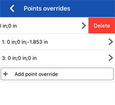
 ) a sinistra della riga. Le sostituzioni di ogni punto elencano il numero di indice seguito dai valori di offset X/Y/Z.
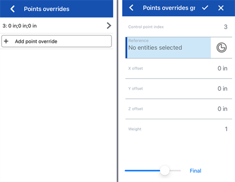
Scorri verso sinistra e tocca il pulsante Elimina per cancellare le sovrascritture di tale punto:
Se necessario, modifica ciascuna delle seguenti opzioni di sovrascrittura del punto di controllo:
-
Indice del punto di controllo: è l'indice del punto di controllo che stai per sovrascrivere. Seleziona l'indice/ID di un punto sulla curva. L'indicizzazione inizia da 0.
La commutazione dei numeri di indice dei punti di controllo a questo livello applica tutte le impostazioni correnti di sostituzione dei punti a tale punto di controllo. In questo modo, è possibile trasferire istantaneamente le impostazioni di sovrascrittura da un punto di controllo a un altro.
Modifica le seguenti impostazioni di sovrascrittura per ogni punto di controllo sulla curva:
-
Riferimento: il riferimento predefinito è la posizione del punto di controllo invariata (punto di origine del manipolatore della triade). Seleziona un vertice, un punto di schizzo o un mate connector esplicito o implicito per rendere i valori di offset X/Y/Z del punto corrente relativi a questo punto.
Per creare un mate connector implicito durante la modifica del punto di controllo, tocca l'icona Seleziona mate connector, quindi tocca una posizione nel modello per creare il mate connector. Questo è ora utilizzato come punto di riferimento.
-
Offset X/Y/Z: visualizza la posizione corrente del punto di controllo, poiché è sottoposta a offset rispetto al suo riferimento. Se necessario, inserisci i valori numerici di offset in ogni campo.
-
Spessore: determina lo spessore del punto di controllo rispetto alla curva. Valori di spessore più elevati avvicinano la curva al punto di controllo. Inserisci un valore di spessore per moltiplicare l'influenza del punto sulla curva di tale quantità.
-
-
Aggiungi sovrascrittura punto: aggiunge una nuova sovrascrittura punto nella tabella con l'indice correntemente selezionato o il primo indice inutilizzato nell'array dopo l'indice corrente, se l'indice corrente è già utilizzato.
-
-
(Facoltativo) Per impostazione predefinita l'opzione Mostra dettagli è abilitata e fornisce una visualizzazione di sola lettura del valore del grado, del numero di punti di controllo e del numero di Segmenti annodati. Deseleziona l'opzione per nascondere questi dettagli.
-
(Facoltativo) Se la curva è stata riapprossimata, puoi attivare l'opzione Mostra deviazione per visualizzare la deviazione massima tra la curva originale e la curva riapprossimata.
-
Tocca il segno di spunta nella parte superiore della finestra di dialogo per accettare le curve modificate e chiudere la finestra di dialogo.
Modifica una curva esistente o crea una nuova curva selezionando entità o curve di schizzo per applicare un'approssimazione semplificata, elevare il grado, riposizionare i vertici della curva di controllo e/o renderla piana in qualsiasi piano 2D.
Passaggi
Con almeno un'entità dello schizzo lineare o una curva disponibile nell'area grafica:
-
Tocca l'icona dello strumento Modifica curva (
 ).
).
-
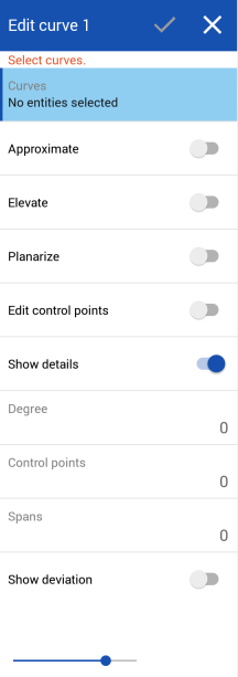
Seleziona una o più entità dello schizzo lineare e/o curve che non si intersecano nell'area grafica. Le entità o le curve dello schizzo devono seguire un percorso continuo e, se sono selezionate più curve, devono essere riapprossimate (seleziona Approssima di seguito), che genera una nuova curva.
-
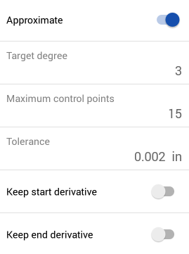
Tocca l'interruttore accanto ad Approssima per aprire opzioni che consentono di riapprossimare la curva. La curva originale è visualizzata in arancione e la nuova curva approssimata in magenta. Approssima tenta di mantenere la geometria della curva, ma ciò non è sempre garantito.
-
Grado destinazione: inserisci il grado della curva destinazione per la curva selezionata.
-
Numero massimo di punti di controllo: inserisci il numero massimo di punti di controllo consentiti per la curva selezionata.
-
Tolleranza: la tolleranza della curva selezionata, come misura della lunghezza. Inserisci il valore della tolleranza.
-
Conserva derivata di inizio: seleziona questa opzione per mantenere la tangenza all'inizio della curva selezionata.
-
Conserva derivata di fine: seleziona questa opzione per mantenere la tangenza alla fine della curva selezionata.
-
-
Tocca l'interruttore accanto a Eleva per aprire l'opzione Grado destinazione. Se necessario, inserisci un grado di curva destinazione più elevato per la curva selezionata. Questo risulta utile per raggiungere il grado desiderato, migliorare la connettività o ottenere un controllo più preciso sulla forma della curva. La geometria della curva è conservata.
-
Tocca l'interruttore accanto a Rendi piana per accedere a opzioni che consentono di raddrizzare la curva lungo un piano di riferimento. Rendere piana la curva proietta le curve di controllo dalla loro posizione corrente al piano di riferimento selezionato:
Le opzioni del piano di riferimento sono:
-
Adatta: proietta la curva lungo il piano che corrisponde maggiormente al percorso della curva (utilizzando la media di tutte le posizioni del punto di controllo).
-
Blocca estremità: verifica che i punti finali della curva siano fissi e non si muovano. Questo è utile per preservare la continuità con la geometria associata.
-
Piano YZ: proietta la curva lungo il piano YZ (normale all'asse X).
-
Piano XZ: proietta la curva lungo il piano XZ (normale all'asse Y).
-
Piano XY: proietta la curva lungo il piano XY (normale all'asse Z).
-
Personalizzato: proietta la curva lungo un piano personalizzato o gli assi XY di un mate connector esplicito o implicito (normale al suo asse Z).
-
-
Seleziona Modifica punti di controllo per aprire le opzioni per aggiungere un riferimento, quindi modifica la posizione e lo spessore dei singoli punti di controllo sulla curva selezionata:
Una volta attivata l'opzione Modifica punti di controllo, il manipolatore della triade è visibile nell'area grafica e la sua origine è posizionata sul primo punto di controllo (indice del punto di controllo 0).
Questo campo dell'Indice punto di controllo è l'indice/l'ID di primo livello di un punto sulla curva e inizia da 0. È possibile selezionare ciascun punto di controllo numericamente inserendo il numero di indice in questo campo. Durante questa operazione il manipolatore triade si sposta sul punto di controllo corrispondente nell'area grafica.
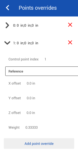
È possibile aggiungere impostazioni di sovrascrittura singolarmente per ogni punto di controllo sulla curva. Tocca il pulsante Aggiungi sovrascrittura punto (disponibile nella sezione Sovrascritture punti della finestra di dialogo) per aggiungere impostazioni di sovrascrittura personalizzate a un punto aggiuntivo. A ogni punto è possibile applicare un solo set di impostazioni di sovrascrittura. Selezionando l'opzione Aggiungi sovrascrittura punto o regolando il manipolatore triade si aggiunge un'opzione di sovrascrittura per il punto attualmente selezionato.
Espandi o comprimi le sovrascritture di ogni riga/punto di controllo premendo l'accento circonflesso (
 ) a sinistra della riga. Le sovrascritture di ogni punto elencano il numero di indice seguito dai valori di offset X/Y/Z. Tocca la x rossa a destra di ogni riga per cancellare le sovrascritture del relativo punto.
Se necessario, modifica ciascuna delle seguenti opzioni di sovrascrittura del punto di controllo:
-
Indice del punto di controllo: è l'indice del punto di controllo che stai per sovrascrivere. Seleziona l'indice/ID di un punto sulla curva. L'indicizzazione inizia da 0.
La commutazione dei numeri di indice dei punti di controllo a questo livello applica tutte le impostazioni correnti di sostituzione dei punti a tale punto di controllo. In questo modo, è possibile trasferire istantaneamente le impostazioni di sovrascrittura da un punto di controllo a un altro.
Modifica le seguenti impostazioni di sovrascrittura per ogni punto di controllo sulla curva:
-
Riferimento: il riferimento predefinito è la posizione del punto di controllo invariata (punto di origine del manipolatore della triade). Seleziona un vertice, un punto di schizzo o un mate connector esplicito o implicito per rendere i valori di offset X/Y/Z del punto corrente relativi a questo punto.
Per creare un mate connector implicito durante la modifica del punto di controllo, tocca l'icona Seleziona mate connector, quindi tocca una posizione nel modello per creare il mate connector. Questo è ora utilizzato come punto di riferimento.
-
Offset X/Y/Z: visualizza la posizione corrente del punto di controllo, poiché è sottoposta a offset rispetto al suo riferimento. Se necessario, inserisci i valori numerici di offset in ogni campo.
-
Spessore: determina lo spessore del punto di controllo rispetto alla curva. Valori di spessore più elevati avvicinano la curva al punto di controllo. Inserisci un valore di spessore per moltiplicare l'influenza del punto sulla curva di tale quantità.
-
-
Aggiungi sovrascrittura punto: aggiunge una nuova sovrascrittura punto nella tabella con l'indice correntemente selezionato o il primo indice inutilizzato nell'array dopo l'indice corrente, se l'indice corrente è già utilizzato.
-
-
(Facoltativo) Per impostazione predefinita l'opzione Mostra dettagli è abilitata e fornisce una visualizzazione di sola lettura del valore del grado, del numero di punti di controllo e del numero di Segmenti annodati. Deseleziona l'opzione per nascondere questi dettagli.
-
(Facoltativo) Se la curva è stata riapprossimata, puoi attivare l'opzione Mostra deviazione per visualizzare la deviazione massima tra la curva originale e la curva riapprossimata.
-
Tocca il segno di spunta nella parte superiore della finestra di dialogo per accettare le curve modificate e chiudere la finestra di dialogo.
Oltre agli strumenti per la creazione di superfici, le curve sono utilizzate per creare gli elementi costitutivi di base delle superfici.
Questo elenca la raccolta di strumenti funzione curva. (L’elenco non è esauriente.) Per manipolare le curve è possibile utilizzare strumenti funzione aggiuntivi.
- Strumenti dischizzo - Strumenti nella barra strumenti dello schizzo come Linea, Rettangolo dello spigolo, Rettangolo a punto centrale, Cerchio da punto centrale, Cerchio a 3 punti, Arco tangente, Arco a 3 punti, Spline, Punto e Costruzione utilizzati per creare uno schizzo in un Part Studio.
-
 Elica: crea un'elica utilizzando una faccia conica o cilindrica, un asse singolo o un asse z di un mate connector o bordo circolare.
 -
 Spline ottimizzata 3D: crea una spline ottimizzata 3D attraverso una serie di vertici. Crea una curva che è elencata nell'elenco delle parti alla voce Curve.
 -
 Curva proiettata: crea una curva dalla proiezione di due schizzi (opzione Due schizzi) o dalla proiezione di una curva su una faccia (opzione Da curva a faccia).
 -
 Curva ponte: crea una curva che collega due punti, vertici o mate connector qualsiasi. La curva risultante è elencata nell'elenco funzioni e nell'elenco delle parti.
 -
 Curva composita: rappresenta più bordi come un'unica curva. Seleziona più bordi adiacenti, entità di schizzo e altre curve. La selezione di bordi non contigui può comportare la creazione di più curve. Le selezioni per ogni curva devono incontrarsi nei rispettivi vertici. (Le curve sono elencate nell'elenco Parti > Curve).
 -
 Curva di intersezione: crea una curva all'intersezione di due o più superfici o facce. Le selezioni devono intersecarsi.
 -
 Accorcia curva: accorcia o estendi una curva di una distanza o fino a un'entità vincolante.
 -
 Isoclina: crea un'isoclina su una faccia inclinata. Un'isoclina scorre su una faccia nelle posizioni in cui la faccia ha una specifica pendenza rispetto alla sua definizione di riferimento. L'isoclina risultante è elencata nell'elenco funzioni e nell'elenco delle parti.
 -
 Curva di offset: consente di creare ed estendere e/o dividere una nuova curva spostando i bordi sulle facce circostanti.
 -
 Curva isoparametrica: crea curve morbide che corrono lungo una faccia o una superficie in direzione U o V.
 -
 Modifica curva: modifica una curva esistente selezionando entità o curve di schizzo per applicare un'approssimazione semplificata, elevare il grado, riposizionare i vertici della curva di controllo e/o rendere piano in qualsiasi piano 2D.
 -
 Curva di routing: crea una curva multipunto su uno o più piani nello spazio 3D (percorso di routing). Questo è utile per creare percorsi di tubazioni, cablaggi e curve NURBS per la creazione di superfici avanzate.