![]()
![]()
![]()
Use the mouse settings and view tools to view models in the graphics area.
View navigation
Onshape provides the following default input device navigation settings:
| Default navigation (input device) | Windows | MacOS | iOS & Android |
|---|---|---|---|
| 3D rotate (mouse) |
Right-mouse-button click, then drag Alt key animates to nearest 'floor down' view (nearest view without any roll) Alt + Right Mouse button: horizontal mouse movement about model; vertical mouse movement pitches over model Left-mouse-button click on View cube arrows: Rotate in 15 degree increments Shift + Left-mouse-button click on View cube arrows: Rotate in 90 degree increments Ctrl+ Left-mouse-button click on View cube arrows: Rotate in 5 degree increments |
Right-mouse-button click, then drag Left-mouse-button click on View cube arrows: Rotate in 15 degree increments Shift + Left-mouse-button click on View cube arrows: Rotate in 90 degree increments Ctrl+ Left-mouse-button click on View cube arrows: Rotate in 5 degree increments |
|
| 3D rotate (keyboard) |
Arrow key (← → ↑ ↓): Rotate 15 degrees Shift + Arrow key (← → ↑ ↓): Rotate 90 degrees Ctrl + Arrow key (← → ↑ ↓): Rotate 5 degrees Press + hold Arrow key (← → ↑ ↓): Continuously rotate |
||
| 3D rotate (touchpad) | Right-touchpad-button click, then drag | Two finger click, then drag | |
| 3D rotate (touchscreen) | Single finger press, then drag | ||
| Zoom in / out (mouse) |
Scroll wheel down: Zoom out Scroll wheel up: Zoom in |
|
|
| Zoom in / out (keyboard) |
Z: Zoom out Shift + Z: Zoom in |
||
| Zoom in / out (touchpad) |
Two finger press, then pinch out: Zoom out Two finger press, then pinch in: Zoom in |
Two finger gesture to scroll down: Zoom out Two finger gesture to scroll up: Zoom in |
|
| Zoom in / out (touchscreen) |
Two finger press, then pinch out: Zoom out Two finger press, then pinch in: Zoom in |
||
| 2D pan (mouse) | Ctrl + Right-mouse-button click, then drag / Middle-mouse-button click, then drag | ||
| 2D pan (keyboard) | Ctrl + Shift + Arrow key (← → ↑ ↓) | ||
| 2D pan (touchpad) | Ctrl + Right-touchpad-button click, then drag | While holding Ctrl key, Two finger click, then drag | |
| 2D pan (touchscreen) | Two finger press, then drag | ||
| Trimetric view (all devices) | Click View cube corner | Click View cube, then select Trimetric from menu | |
| Plane view (all devices) | Click View cube side (Top, Bottom, Front, Back, Left, Right) | Click View cube, then select plane from menu (Top, Bottom, Front, Back, Left, Right) | |
Navigation commands can vary depending on your machine and input device settings.
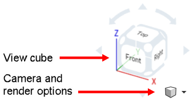
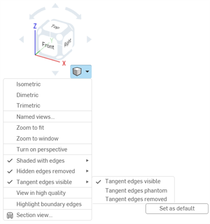
Camera and render options
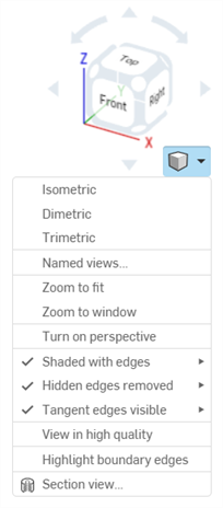
The small cube, Camera and render options, offers these viewing options:
|
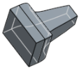
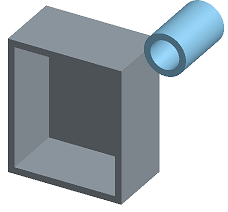
Shaded |
|
|
Shaded without edges |
|
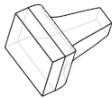
| Shaded with hidden edges |
|
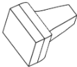
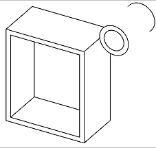
| Hidden edges removed |
|
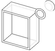
| Hidden edges visible |
|
| Tangent edges visible/phantom/removed (Viewable only on Browser platform, and only within Part Studios). |
|
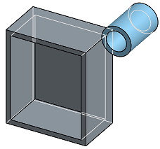
| Translucent |
|
Camera and render option defaults
Some Camera and render options can have their settings default to enabled or disabled:
-
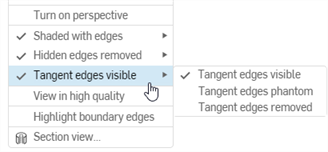
Perspective view / Highlight boundary edges - These options are disabled by default. To set their default to enabled:
-
Left click to enable the option.
-
Right-click and select Set as default.
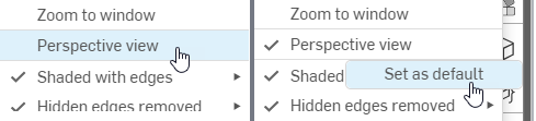
Left-clicking to turn Perspective view on (left), then right-clicking to select Set as default (right)
-
To set the option's default back to disabled:
-
Left click to disable the option.
-
Right-click and select Set as default.
-
-
-
Shaded edges / Hidden edges / Tangent edges - Right-click on any disabled sub-option and click Set as default. This simultaneously enables that option and sets it as the default:
The mouse wheel direction for zoom is configurable in user account preferences.
To zoom:
- Zoom to fit (shortcut: f, double-click scroll wheel) - Select this command or use the shortcut key to zoom the entire Part Studio, Assembly or Drawing into view.
- Zoom to window (shortcut: w) - Select this command, then click+drag a box around the area you want to zoom to in a Part Studio, Assembly or Drawing. The shortcut key toggles the feature on and off.
- Zoom to selection - Select this command to zoom to the selected entities.
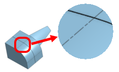
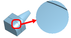
Tangent edges are edges formed between a curve and linear edge; for example, from fillets or smooth edges.
To select the visual treatment of tangent lines, select from the following three view modes:
- Visible - Tangent edges are shown as solid lines. This is the default.
- Phantom - Tangent edges are displayed as dashed lines; also known as Font in some systems.
- Removed - Tangent edges are visually removed from view.
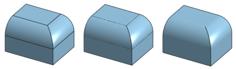
Three different tangent edge options, from left to right: Visible (default), Phantom, and Removed.
Tangent edges are currently only available for newly created models in a Part Studio or Assembly, and only on the browser platform.
Set the level of transparency of a part through the Part context menu; right-click on a part name in the Parts list and select Appearance editor. See Customizing Parts: Appearance for more information.
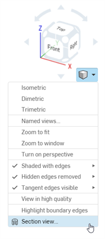
Section view allows for the selection of one or many planes, Mate connectors, cylindrical faces, conical faces, or planar faces to use for sectioning. Section view can be turned on through the view cube, or by selecting Section view in the context menu.
Once the manipulator is visible, it can be moved via the ball (open circle at its center) and snapped to any inference point on the part, surface, or assembly. Sectioned items are viewable in both Part Studios and Assemblies:
- Select one or many planes, Mate connectors, cylindrical faces, conical faces, or planar faces on the part or surface.
- Expand the Camera and render options menu
 and select Section view
 (shown below). Alternatively, right-click on a part in the Part Studio or an assembly in an Assembly tab, and select Section view from the context menu:
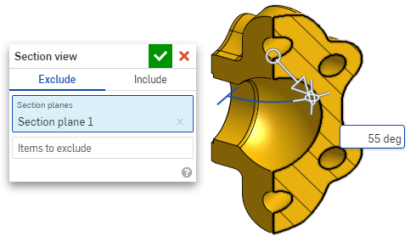
- The part/surface is sectioned at the point chosen in step 1 above (cylindrical face, conical face, planar face, plane, or Mate connector). A manipulator appears at the last location selected and a dialog opens listing selections:
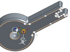
- Click and drag the open circle (ball) of the manipulator to position it. Notice you can snap it to any inference point on the part or assembly, including the centroids of cylinders (the white marks below indicate inference points):
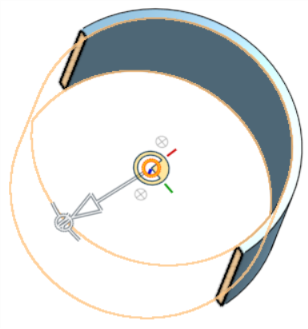
- Use the manipulator to change the depth and/or angle of the section.
- Use the arrow to change the depth, dragging in one direction or another. Click the manipulator to flip the direction of the view.
- Use the angle indicators to drag at an angle.
- Use the numeric field to type the depth or angle of the view.
- To select a different sectioning plane while the dialog box remains open, simply click on the desired location for this new sectioning plane, and a new manipulator and section plane appears.
- To view the section normal to the section view plane, use shortcut key n or right-click and select View normal to from the context menu.
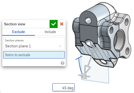
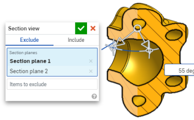
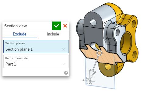
- To exclude a part or parts (surface or surfaces) from being sectioned, activate the Items to exclude field then make your selections in the graphics area:
-
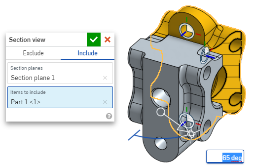
To include a part or parts (surface or surfaces) in the section, select the Include tab, then select the items to include in the graphics area:
- It is possible to move the model while in section view. Click out of the dialog box to close it, then manipulate the model as desired.
-
If Section view is not turned off and the dialog box is closed, open the dialog again by double-clicking on the section plane. Alternatively, click the Camera and render options menu
or right-click on the part or assembly to access the context menu, and select Edit section view.
-
Select Turn off section view
from the Camera and render options menu
or context menu when finished.
- Front view = Shift 1
- Back view = Shift 2
- Left view = Shift 3
- Right view = Shift 4
- Top view = Shift 5
- Bottom view = Shift 6
- Isometric view = Shift 7
- Section view = Shift X
- Named view = Shift V
You can also turn on Section view before making any selections.
Intersecting parts, if they exist, are rendered in red.
You can use Section view and then save the view as a Named View.
You can also use the Measure tool on faces, edges, and vertices while in a Section view. See Measure tool and Assembly measure tool for more information.
Keyboard shortcuts for view
Use Zoom to selection to change the view to a close-up of the selected entities.
Make a selection in the graphics area:
Expand the View menu and select Zoom to selection:
shift+r
Toggle to select/deselect the highest available quality tessellation view for the currently active Part Studio or Assembly. Be aware that this may result in a slight degradation of performance. When you turn this option on, the blue notifications are displayed as shown below:
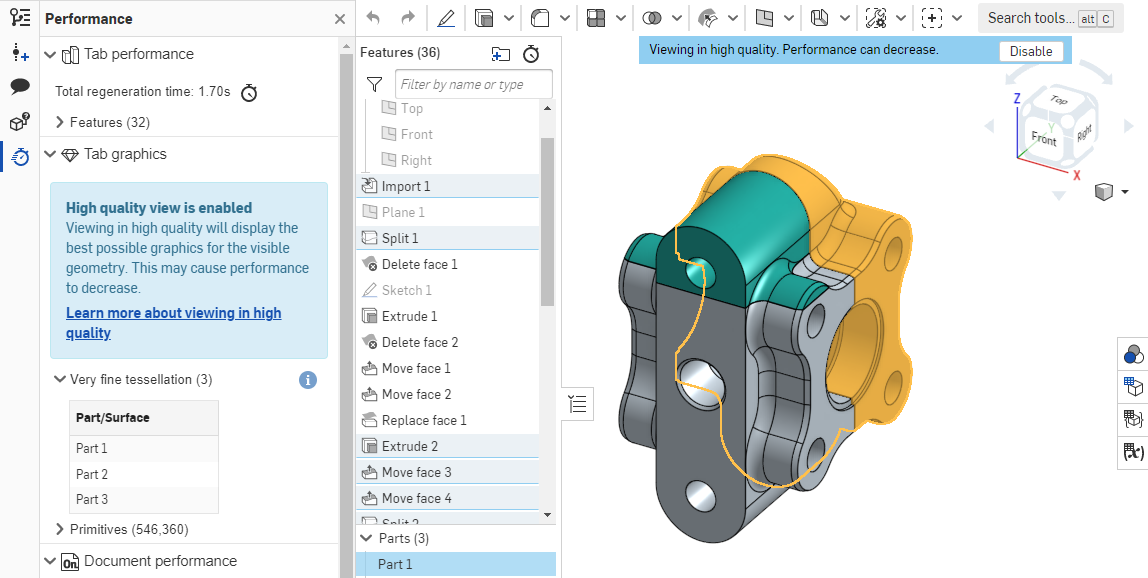
For more information on how this view mode may affect performance, see High quality mode.
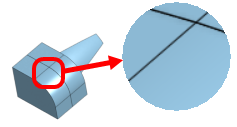
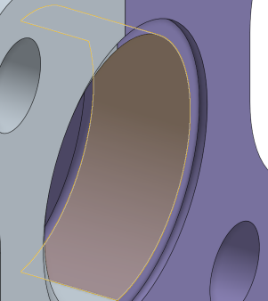
Onshape displays holes and disconnects in a model, including laminar edges of surfaces, that may be in need of repair when you select Highlight boundary edges. This feature is especially helpful when importing parts that require repairing surfaces.
Select Highlight boundary edges in the Camera and render options menu. Edges that may require repair are highlighted in solid red lines when the edges are visible and dashed red lines when the edges are hidden:
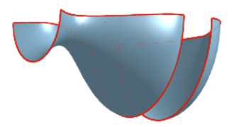
This tool is available only in Part Studios. For more information, see Repairing Imported Models.
![]()
![]()
3D Rotate Lock, when active, locks the user's ability to 3D rotate the graphics area. This is particularly useful when attempting to select and drag an entity.
It is located directly above the View Cube in both Part Studios and Assemblies.
To activate the 3D Rotate Lock, tap the button. To deactivate, tap the button again or commit a feature.
3D Rotate Lock activates by default in certain situations:
- Part Studio - If a sketch is open and an entity is selected, the 3D Rotate Lock turns on by default. This allows for the selection to be dragged without the view rotating. Unlock by tapping the button.
- Assembly - If an instance, Mate connector, or entity is selected, the 3D Rotate Lock turns on by default. This allows for the selection to be dragged without the view rotating. Unlock by tapping the button.
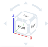
The View cube is located in the upper right corner of the graphics area. When selected, a list of different viewing options appears. Select one to change the view of your graphics area or the view settings of your part(s). This is an easy and quick way to get a well-oriented view of your part(s) without having to 2D/3D rotate or zoom.
- Tap the View cube. A list of options appears.
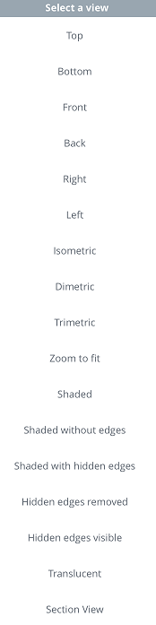
- Tap to select a view option or select Cancel.
- Scroll to see more options.
- Top, Bottom, Front, Back, Right, and Left - Select any of these options for a front-facing view of the respective plane.
- Isometric, Dimetric, Trimetric - Select any of these for the respective angled view.
- Zoom to fit - Select to resize the graphics area to fit the screen. This could result in the view zooming in or out.
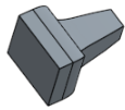
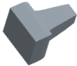
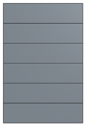
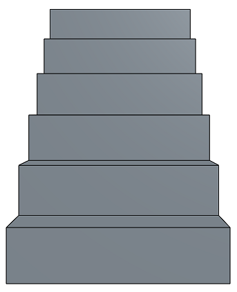
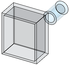
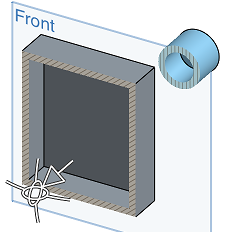
- Perspective View - Toggle perspective view on and off. Perspective view shows the relative distance from the point of view to the model, and creates a vanishing point as the point of view (or imaginary camera) approaches the model. The images below show a front view of the same part without perspective view and with perspective view, respectively.
- Shaded - Select to show the part with shaded faces and edges. (Default)
- Shaded without edges - Select to show part shaded, without edges.
- Shaded with hidden edges - Select to show the part shaded and to show hidden edges (edges that aren't in the direct line of sight).
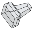
- Hidden edges removed - Select to show the part unshaded, with the hidden edges (edges not in direct line of sight) removed.
- Hidden edges visible - Select to show the part unshaded, with the hidden edges (edges not in direct line of sight) visible.
- Translucent - Select to show the part as translucent.
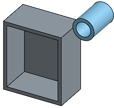
- Section View - Select to access a manipulator that allows you to adjust a section view of a part, via a plane or planar face.
You must preselect a plane or planar face before selecting Section View.
Drag the arrow or either directional manipulator to adjust the section view plane that is created from the preselected plane or planar face. In this case, the Front plane is used to create a section view roughly halfway through the parts.