![]()
![]()
![]()
Available in: Part Studio, Assembly
Create variations of a part, Part Studio, or assembly. For example, you can configure the depth of an extrude feature, the suppression of a fillet, the FeatureScript of a custom feature, part numbers, colors, materials, and more.
In an assembly, you can only configure mates (not mate connectors), instances, and patterns. You can configure an assembly regardless of any Part Studio configurations.
Configurations are created only on a browser but can be viewed on iOS and Android.
See the following pages for more details on working with configurations:
-
Managing Configurations (including renaming, filtering, copy/pasting, etc.)
-
Visibility Configurations (configuration logic)
Configurations are created only on a browser (in a Part Studio or an Assembly). Create part families by creating variations of an entire Part Studio or specific part. You are able to configure any feature or parameter value and even part properties, custom part properties, face and part appearance, and sketch text. For example, you are able to configure the depth of an extrude feature, the application of a fillet feature, the faces selected for a fillet, the FeatureScript of a custom feature, and part numbers, colors, and materials.
All the features and parameters you configure in one Part Studio is a Configuration. Each Part Studio can have one Configuration; however, you can create multiple Configuration inputs within one Configuration.
The Configuration inputs you define in a Part Studio become options in the Insert dialog when you are inserting parts into an Assembly or Drawing.
In this example, two configurations are created: a new sheet thickness configuration, and an alternate flange configuration. With the model in the workspace, click the Configuration icon to open the Configuration panel. Click the Configure Part Studio button. Enter Sheet thickness as the configuration name. Click tab to create a new row, and enter Alternate flange as the second configuration name. Each row is a different configuration.
With the Sheet thickness row selected, click the Configure features button. Double-click the feature that contains the parameter in the Features list. Select the parameter to outline it with a dashed yellow line, in this case the Sheet thickness parameter. A new column for the parameter is created in the table. Double-click the table cell, and provide a new value. Next, select the Alternate flange configuration row and do the same, using the Flange feature, and providing alternate values for the Distance and Bend angle in the table.
To test the inputs with the model, click the dropdown arrow in the Configurations area of the Features list, and select the new configurations to see the results. The model updates, using the new input parameters.
- Click the Configuration panel icon (
 ) on the right side of the screen.
-
The Configuration panel opens. Click Configure Part Studio or Configure Assembly to add an input:
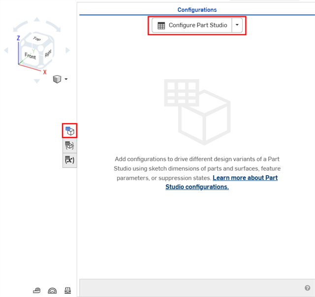
Creating a configuration in a Part Studio
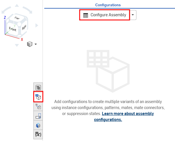
Creating a configuration in an assembly
By default, the caret to the left of 'Configuration' is expanded, click the caret when you are done with a section of the panel to collapse that section.
- Click in the first row to activate it, and enter the input value names in the first column. Press Tab to move to the next row. The blue bar to the left of the row indicates the currently selected configuration in the Onshape window.
This example has 3 possible configurations: Short, Medium, and Tall.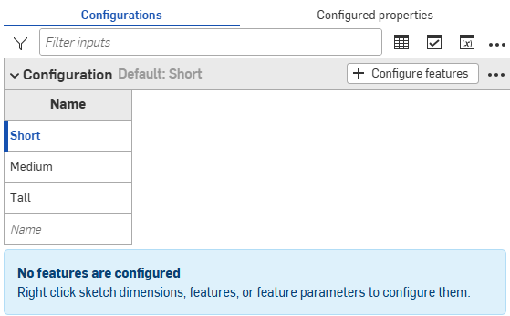
- To configure a feature for the selected input value, click + Configure features (or + Configure assembly features).
- Click the feature or instance to configure and select the parameter. The parameter is outlined with a broken yellow line and a new column is created for that parameter.
For example, click an Extrude feature in the Features list, and select the Depth parameter in the Extrude dialog. The parameter is highlighted in yellow in the dialog, and a new column appears in the table.
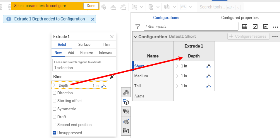
The column name defaults to the feature name (as a top-level heading) plus the parameter name (as the subordinate-level heading), in this case Extrude 1 is the Feature name and Depth is the field name.
Hover over the fields in the feature dialog to see which parameters can be configured. Parameters available for configuration are highlighted in yellow when you hover over them.
You can configure Tolerance options (
 ) for many sketch and feature dimensions directly in the Configurations table. Each option value can have their own Tolerance options settings.
 - To configure the parameter:
- To edit a value, double-click it, and enter the new value.
For this example, set the depths for the 3 input values: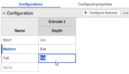
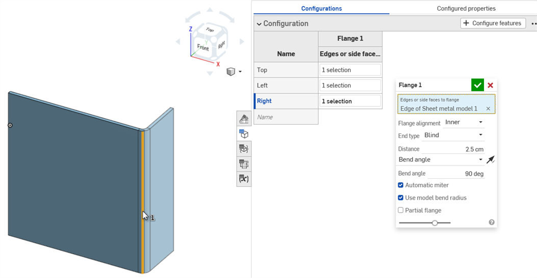
- To edit a selection in a dialog, double-click the configured parameter in the table to open the feature dialog.
The parameter in the feature dialog is highlighted in blue. Remove any unwanted selections, and make the new selections on the model or sketch. Click the green checkmark in the feature dialog to close it.
- To edit a value, double-click it, and enter the new value.
- When finished defining the configurations, click the Done button in the yellow banner.
- To add another parameter (column) to the input, repeat Steps 4-7.
- To add additional list inputs, click the Add configuration input button at the bottom of the Configuration panel, then select List.
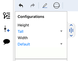
- To test the inputs with the model, under
Configurations in the left panel, use the down arrow to select from the menu:
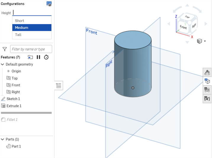
The model should update accordingly. If it does not, check the model for design intent and the configurations definition for accurate selection.
Create a checkbox to turn options on or off (such as fillets or chamfers), and suppress or unsuppress features. This presents a checkbox in the Insert dialog during insertion time.
-
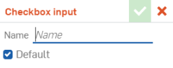
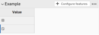
Click the Add configuration input button at the bottom of the Configuration panel, then select Checkbox:

- The Checkbox input dialog opens. Enter a name for the input.
-
The configuration input has one column with an empty checkbox row and a checked checkbox row. Click + Configure features (or + Configure assembly features).
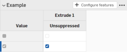
- In the Feature list, click the feature that contains the parameter and select the parameter. The parameter is then outlined with a broken yellow line and a new column is created for that parameter in the table. (Parameters that are configured in another input are outlined with a broken yellow line and are unavailable for configuration.)
In this example, Unsuppressed is selected as a configuration input parameter.
- Click X to close the feature dialog.
- Uncheck the box in the first column to indicate that a checked box should insert an unsuppressed feature:
-
Click the Add configuration input button at the bottom of the Configuration panel, then select Configuration variable:
- Enter a name for the variable input in the Variable input dialog. This becomes an actual variable in the system, referenced as #variableName.
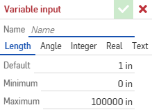
- Select a type for the variable: Length, Angle, Integer, Real, Text. Text can be any type of text that can be used in custom FeatureScript.
- Enter values for the type of variable you selected.
- Click the checkmark to save your definition.
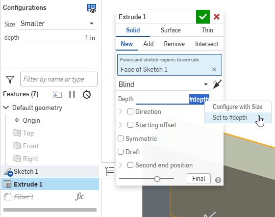
- Apply the variable to a feature:
- Double-click a feature in the Feature list to open it.
- Right-click the input, and click
Set to #variableName. You can also type the variable name (preceded by #) directly into any expression.
- Close the feature dialog. The variable input's usages are listed in the Configuration panel.
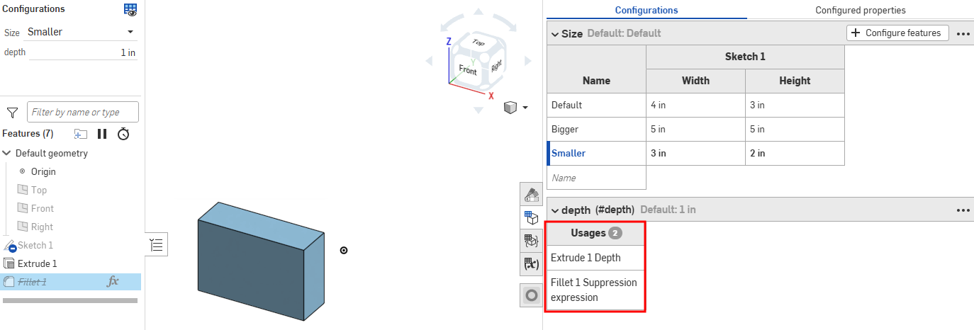
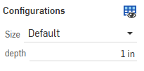
- Test the value by selecting it in the Configurations list above the Feature list on the left side of the page:
You can use the configuration inputs you create directly in the Part Studio or assembly to preview their design. The main use for creating configuration inputs, however, is to select specific configurations to insert into other assemblies, drawings, releases, etc.
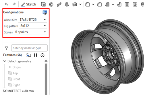
Use the Configurations area at the upper-left of the screen to select configuration inputs to see how they affect the overall design. The design updates to match the selected inputs so you can preview the final design. Every permutation of possible configuration inputs is one configuration.
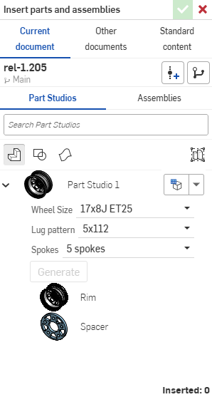
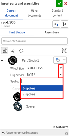
You can insert configured parts, Part Studios, or assemblies into assemblies, releases, and drawings via the Insert Part Studios and Assemblies dialog
-
Select the desired inputs directly in the Insert dialog:
-
Click the Set to last viewed configuration icon (
 ) to select the last active configuration previewed in the Part Studio or assembly tab, or click the arrow and select Reset to default to set all inputs to their default values.
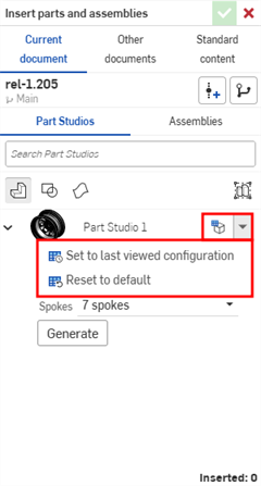
-
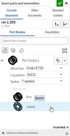
When you are satisfied with the configuration, click Generate.
-
Click the configuration to insert.
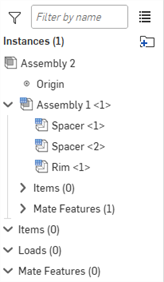
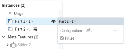
In an Assembly, configured parts and assemblies are indicated by the
![]() icon in the Instances list:
icon in the Instances list:
After a configured part or assembly has been inserted into an assembly, you can change the configuration:
- Right-click on the part or assembly in the Instances list and select
Change configuration.
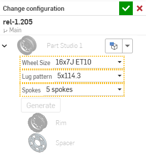
- Select the new configuration values.
-
Click
 when you are satisfied with your selection. (Use
 to cancel the operation.)
To see which configuration is currently active in the Assembly, hover over a part in the Instances list and a tooltip appears with the configuration information:
iOS and Android support for configurations is limited to the following:
-
Viewing the Configuration panel (
) on the right. -
Selecting between Configurations in the left side panel (above the Features list):
Selecting Configurations on iOS
-
(iOS only) Visibility conditions are applied, if they are present in the configuration.
You cannot create or edit configurations or visibility conditions from the iOS or Android platforms. This can only be done from the desktop (browser) platform.
For additional Learning center resources, see: Self-Paced Courses > Configurations. You can also follow the learning pathway course here: Introduction to Part Configurations (Onshape account required), and the technical briefing article here: Parametric Variables vs Configuration Variables (Onshape account required).