 Tolerance Options
![]()
![]()
![]()
Available in: Sketch, Part Studio
Tolerances define the permissible range of values for a specified sketch dimension or Feature parameter, such as Extrude depth, Revolve angle, or Hole diameter. Not all sketch dimensions or Feature parameters can use tolerances.
Tolerances are available in FeatureScript, and can be used in custom features. See Custom features for more information, and refer to FeatureScript for additional documentation.
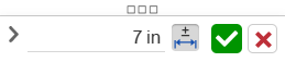
The Dimension context dialog is used to edit sketch and feature dimensions and add tolerances. Double-clicking a dimension in a sketch or an MBD dimension in the graphics area accesses this dialog. See Editing MBD dimensions.
-
Click the tolerance icon (
 ) to add a tolerance to the dimension.
 -
Once a tolerance is set, click the dropdown arrow (
 ) to set the Tolerance parameters:
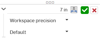
-
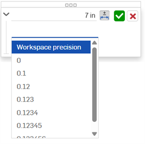
Precision - Use the dropdown to select a unit precision, either Workspace precision or another precision value from the dropdown list; 0 to 6 decimal places.
-
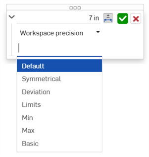
Tolerance type - Select a tolerance type from the dropdown list. Options are: Default, No tolerance, Symmetrical, Deviation, Limits, Min, Max, Basic,
Hole and sketch diameter tolerances also offer Fit, Fit with tolerance, and Fit (tolerance only) options. See the Hole feature for more information.
With Default selected, tolerances are based on Default tolerances. See Onshape default tolerances library and Default tolerances library for further information.
-
Deviation - Available for the Symmetrical Tolerance type. Enter a deviation value.
-
Upper - Available for the Deviation and Limits Tolerance types. Enter the upper tolerance value.
-
Lower -Available for the Deviation and Limits Tolerance types. Enter the lower tolerance value.
-
Standard - Available for the Fit, Fit with tolerance, and Fit (tolerance only) Tolerance types. Select the ANSI or ISO standard from the dropdown list.
- Fit type - Available for the Fit, Fit with tolerance, and Fit (tolerance only) Tolerance types. Select User defined, Clearance, Transition, or Interference from the dropdown list.
- Hole class - Available for the Fit, Fit with tolerance, and Fit (tolerance only) Tolerance types. Select a Hole class option from the dropdown list.
- Shaft class - Available for the Fit, Fit with tolerance, and Fit (tolerance only) Tolerance types. Select a Shaft class from the dropdown list.
-
-
-
Click the checkmark icon (
 ) to accept the values entered in the context dialog.
 -
Click the x icon (
 ) to exit the context dialog without any changes.
 -
Click and drag by the dialog's handle (
 ) to move the dialog to a new location on-screen. Let go of the mouse to place it in its new location.
The following sketch dimensions can use tolerances*:
-
Distance between 2 lines
-
Distance between two points**
-
Distance between sketch geometry and a plane**
-
Diagonal distance**
-
Diameter
-
Angle
-
Direct distance**
-
Linear distance**
-
Radius
-
Centerline
The following sketch dimensions cannot use tolerances:
-
Single line distance. Alternatively, create a distance between 2 lines, points, or sketch geometry and a plane.
-
Arc length
* Of the dimensions that can be made tolerant, a viewable dimension is only shown after the part is created from the sketch, and the Inspection table is opened (and the part is selected using the Model dropdown).
** While these sketch dimensions can be made tolerant, they do not generate a viewable dimension when the Inspection table is opened. This is due to the fact that MBD dimension data relies on measuring from faces of a single part, and these dimensions use points or faces external to the part being measured.
See Sketch tool dimensions for more information.
-
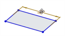
Draw the sketch entity, and enter any values in the on-the-fly value inputs.
-
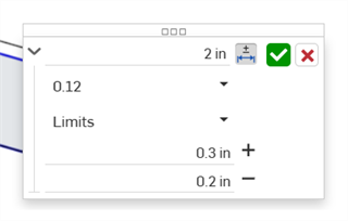
Double-click on the dimension (first image below). The Dimension context dialog opens (second image below):
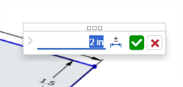
-
To add a tolerance to the dimension, click the Tolerance options icon (
; first image below), and then click the dropdown arrow (; second image below):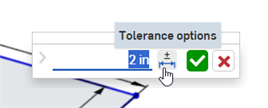
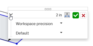
-
Enter The Precision and Tolerance type, with specified values:
-
Click the checkmark (
) to accept the sketch dimension: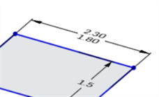
The following Feature options can use tolerances:
-
Extrude
-
Solid/Surface/Thin - Depth
-
Solid/Surface/Thin - Offset distance
-
Solid/Surface/Thin - Second end position - Offset distance
-
Thin - Thickness 1
-
Thin - Thickness 2
-
Thin - Mid plane - Thickness
-
-
Revolve
-
Solid/Surface/Thin - One direction/Symmetric/Two directions - Revolve angle
-
Thin - Thickness 1
-
Thin - Thickness 2
-
Thin - Mid plane - Thickness
-
-
Fillet
-
Radius
-
-
Chamfer
-
Distance (Equal distance)
-
Distance 1, Distance 2 (Two distances)
-
Distance and angle (Distance, Angle)
-
-
Hole
-
Diameter (Simple/Counterbore/Countersink)
-
Distance (Depth: Simple/Counterbore/Countersink)
-
Diameter (Counterbore/Countersink diameter)
-
Distance (Counterbore depth)
-
Angle (Countersink angle)
-
Distance (Tapped depth)
-
Distance (Tap drill diameter)
-
-
Create a feature that accepts a tolerance (Extrude in this example).
-
Click the Tolerance options icon (
) to the right of the parameter: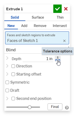
-
Click the dropdown arrow (
) to the left of the parameter: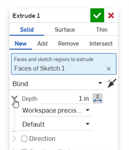
-
Enter The Precision and Tolerance type, with specified values:
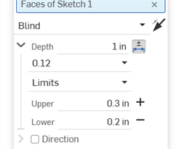
-
Enter any other Feature settings and click the checkmark (
) to accept the Feature. -
Ensure the Inspection table (
 ) is open to see the Feature's dimension value with the tolerance:
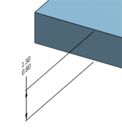
Removing a feature's tolerance does not remove the dimension from the model, as it is still a valid dimension.
Tolerance options can be used in conjunction with configurations.
-
Click the Tolerance options icon (
) to make the configuration's option value tolerant: 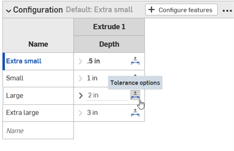
-
Click the dropdown arrow icon (
) to the left of the parameter in order to set the tolerance Precision and Type. 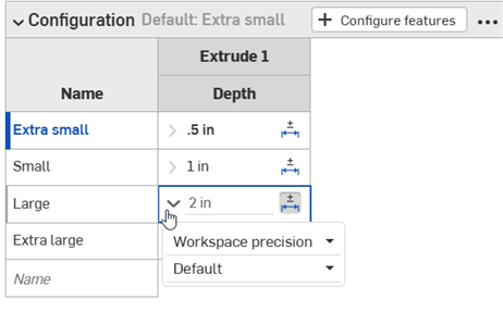
See Configurations for more information.
Tolerance options are automatically used in conjunction with the Compare mechanism. When comparing 2 history entries, select the Feature to compare (Extrude 1 in the example below). Comparisons between differing Tolerance options in the entries are outlined in yellow:
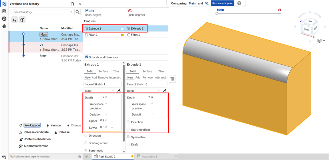
Extrude: Depth tolerance options compared between two history entries
See Compare for more information.
Images below are from iOS. The workflow is the same for both iOS and Android.
Sketch dimension tolerances:
-
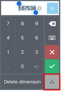
Double-tap the dimension on-screen.
-
Click on the Tolerance options button at the lower right corner of the Android Dimension context dialog to set the dimension as tolerant:
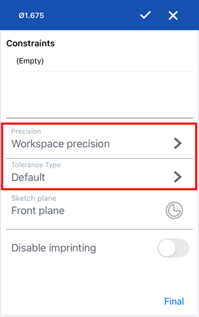
-
In the Tolerance options dialog, enter the Precision and/or Tolerance type and click the checkmark to accept the options:
Feature dimension tolerance:
Feature dimensions can be set and edited in the same way as on the desktop platform:
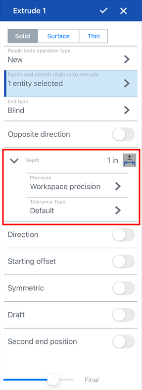
Tolerance options for the Extrude: Depth value
Tolerances can only be viewed on the desktop platform, not iOS or Android, since the Inspection table is available only on desktop.