Model-Based Definition (MBD)
![]()
![]()
![]()
Available in: Part Studio
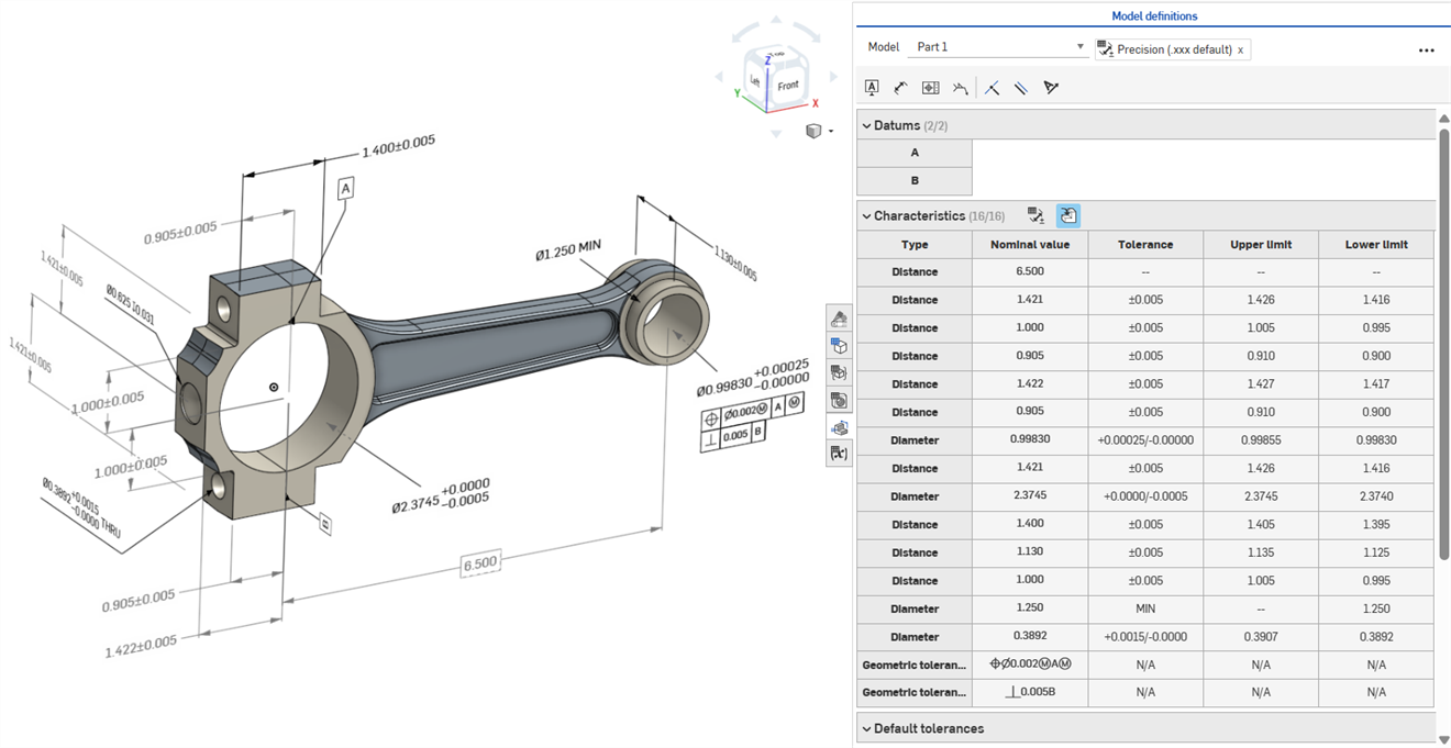
Model-based definition (MBD) refers to the process of dimensioning and annotating the model in the Part Studio so the model contains all the data needed to define a product, With MBD, the model becomes the source authority that drives all engineering activities. This model may further be used downstream by suppliers and across organizations.
MBD data works in conjunction with Tolerance options, where sketch and feature dimensions are made tolerant, and the Inspection table, where MBD data can be viewed, added, and exported for each part in a Part Studio.
MBD is not intended to replace Drawings. MBD is intended to capture and extend a model's Product manufacturing information (PMI) and Model-based enterprise (MBE) information for additional or alternative downstream usage.
Some features of MBD:
-
Dimension and annotation metadata embedded in the model in the Part Studio.
-
Improve real-time collaboration on the model in the Part Studio.
-
Provide a single source of truth for engineers across the organization.
-
Link to downstream processes like Coordinate measuring machine (CMM) inspection.
Driving MBD sketch and feature dimensions can be edited directly from the graphics area.
Product Manufacturing Information can be edited in the graphics area when the Inspection table is open, as well as within the sketches and features where they were originally defined.
Edit tolerances by double-clicking on the dimension in the graphics area. If the dimension references the Features list, Onshape opens the sketch or feature for editing. If the dimension was created using the Annotation toolbar, edit from the graphics area. As the model and tolerances change, the Inspection table updates in real time.
In the Characteristics table, filter rows using two toggle buttons. Initially, annotations with default tolerances applied are shown, and annotations from derived geometry are hidden. Derived annotations can only be updated by modifying the source.
Use cross‑highlighting to quickly identify and locate associated model references. Hover over cells in the Inspection table to cross-highlight the referenced part, faces, features, and associated annotations in the graphics area. Select an annotation in the graphics area or click a Datum or Type cell to keep the highlight visible.
Remove an annotation by selecting it in the graphics area and pressing Delete. Deleting an annotation that references the Features list removes the tolerance options from the sketch dimension or feature value, and removes the row from the Characteristics table. Deleting an annotation placed with the annotation toolbar removes it from the table. Derived annotations cannot be deleted.
-
Open the Inspection panel (
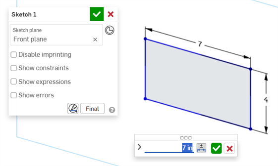
 ) to display the MBD dimensions in the graphics areas (left image below).
 -
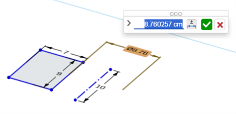
Double-click on the driving dimension that is associated with a sketch (right image below):
The Dimension context dialog opens with context placed on the dimension value. Simultaneously, the Sketch dialog opens:
-
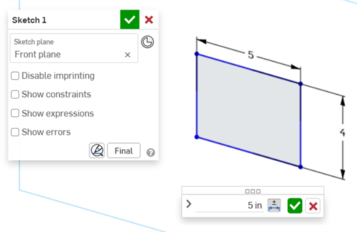
Using the keyboard, enter a numeric value or use the up/down arrows to increment the value in the Dimension context dialog. As this value is adjusted, the sketch is updated dynamically.
If entering a value numerically, press the tab key to see the sketch value update.
-
Press Enter on the keyboard or click the checkmark (
 ) in the Dimension context dialog to close this dialog:
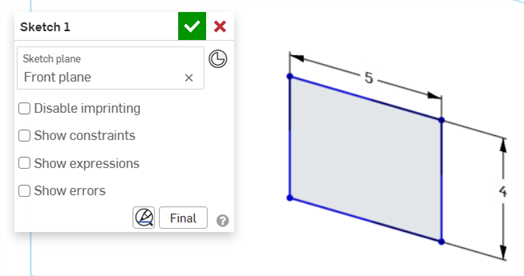
-
Press the checkmark (
) in the Sketch dialog to accept the new sketch value.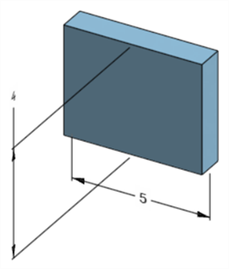
The edited sketch dimension that adjusts the model's dimension
-
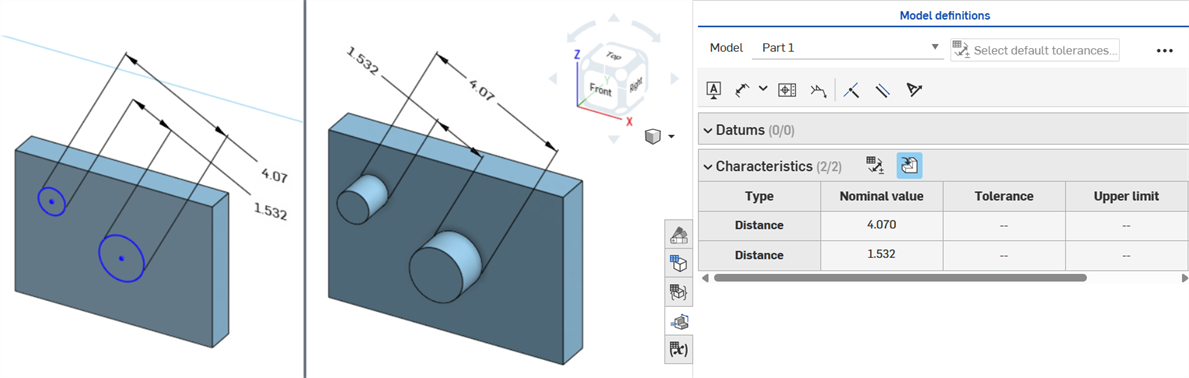
Open the Inspection panel (
) to display the MBD dimensions in the graphics areas (left image below). -
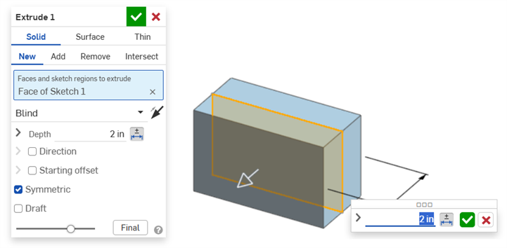
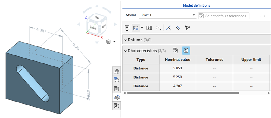
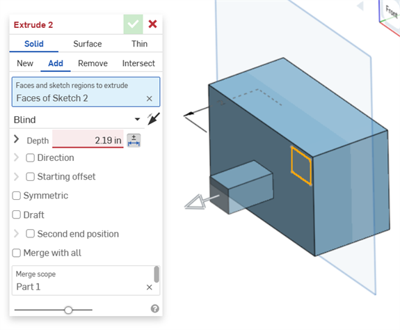
Double-click on the driving dimension that is associated with a feature (right image below):
The Dimension context dialog opens with context placed on the dimension value. Simultaneously, the associated Feature dialog opens (Extrude in this example):
-
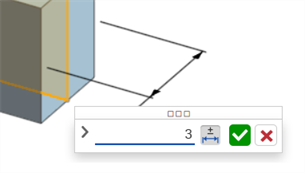
Using the keyboard, enter a numeric value or use the up/down arrows to increment the value in the Dimension context dialog. As this value is adjusted, both the model and the value in the Feature dialog are updated dynamically.
If entering a value numerically, press the tab key to see the value update in the Feature dialog.
-
Press Enter on the keyboard or click the checkmark (
) in the Dimension context dialog to close this dialog: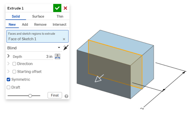
-
Press Enter on the keyboard again or click the Feature dialog checkmark (
) to close this dialog: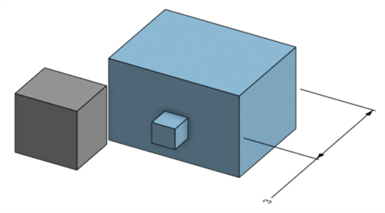
The edited feature dimension that adjusts the model's dimension
To delete an annotation:
-
Select the annotation in the graphics area:
-
Press the Delete key.
-
The annotation is deleted from the graphics area and Inspection table.
If the annotation is a sketch or feature dimension:
-
The dimension's Tolerance options values are deleted.
-
The Tolerance options icon (
 ) is deselected.
 -
The dimension value in the sketch or Feature dialog is not deleted.
-
Annotations cannot be deleted if:
-
The annotation is derived.
-
The annotation is created in a custom feature where the parameter is made tolerant but the tolerant toggle is not made available for user input.
In either case the following message is displayed:

-
Driven dimensions cannot be edited. Double-clicking on a driven dimension opens the Dimension context dialog, but values in the dialog cannot be edited.
-
Derived dimensions cannot be edited. Double-clicking on a driving or driven dimension from a derived part does not open the Dimension context dialog.
-
To cancel out of the Dimension context dialog, press the Esc key. If editing a feature dimension, the Dimension context dialog and Feature dialog close simultaneously. If editing a sketch dimension, only the Dimension context dialog closes. The sketch dialog must be manually closed (clicking the x icon).
-
Alternatively, with both the Feature dialog and Dimension context dialog open, the value in the Feature dialog can be selected and edited, which updates both the Dimension context dialog and model dynamically. Once edited here, pressing Enter closes both the Feature dialog and the Dimension context dialog simultaneously.
-
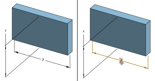
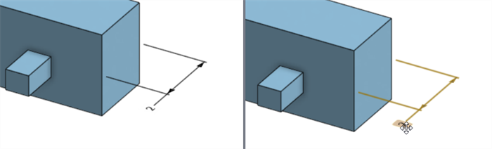
The location of the model dimension and location of its corresponding sketch dimension are not locked together. They are independent:
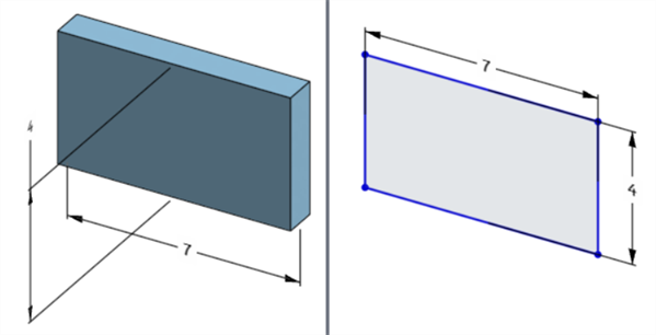
The model's width dimension is located below the model (left) but above the sketch (right)
-
In Pause regeneration mode, the model's dimension cannot be edited or deleted. However, you can still edit the feature or toggle a dimension's tolerance on or off. Changes take effect after clicking the Regenerate features and exit checkmark on the Paused regeneration banner.
-
Configurations work as expected. However, the dimension in the Dimension context dialog is not surrounded by a dashed orange outline to indicate it is configured. Configured sketch dimensions cannot be edited.
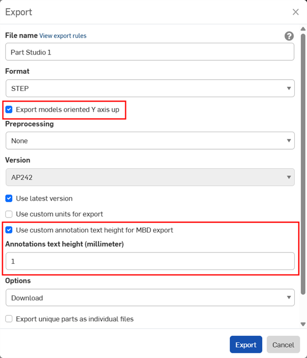
MBD data can be exported to STEP file format when exporting parts. The following settings are recommended:
MBD data is not exported for closed composite parts. This warning is displayed during export in the Export dialog if the document is open. However, if a part is selected and exported from an Advanced search Document results list, the warning is not displayed, but MBD data is still not exported.
-
Enable the Export models oriented Y axis up checkbox.
-
Depending on the size of your model, you may need to enable the Use custom annotation text height for MBD export and select an appropriate Annotations text height to correspond to your model size.
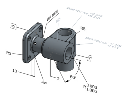
Original model in Onshape
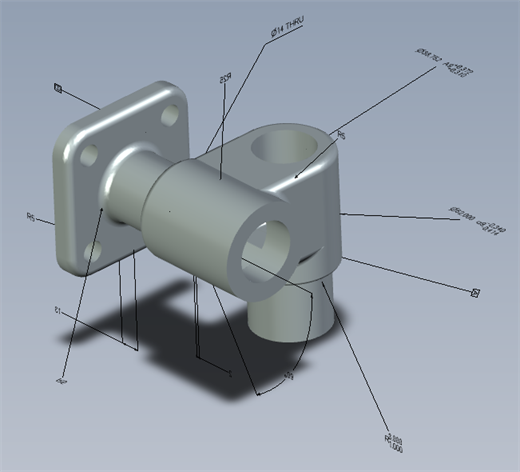
Exported model with the "Use custom annotation text height for MBD export" option disabled
Exported model with the "Use custom annotation text height for MBD export" enabled and set to 10 mm.
When exported, Geometric tolerances with multiple Tolerance frames have Upper text combined with the top frame, and Lower text combined with the bottom frame.
The following provides MBD examples when working with Feature and dimension tolerances:
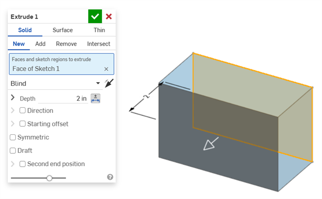
Depth dimension:
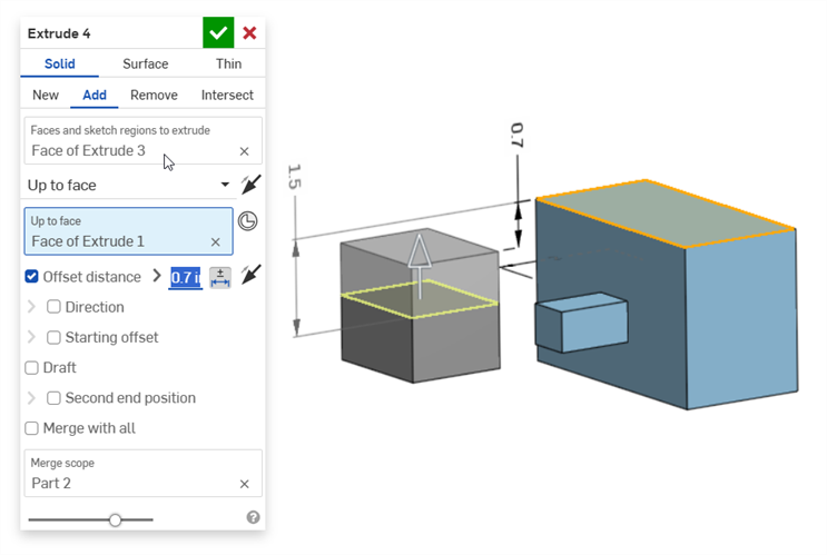
Offset distance dimension (with a composite part):
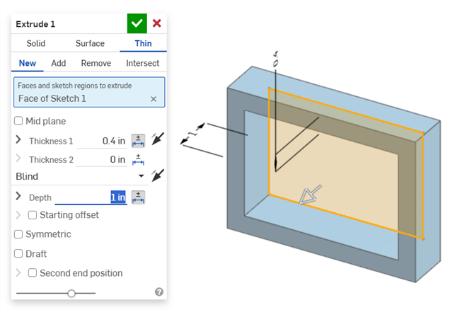
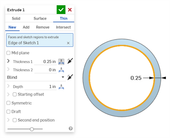
Thin extrude (Thickness 1 and Depth dimensions):
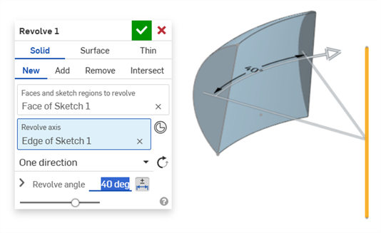
Revolve (Revolve angle dimension):
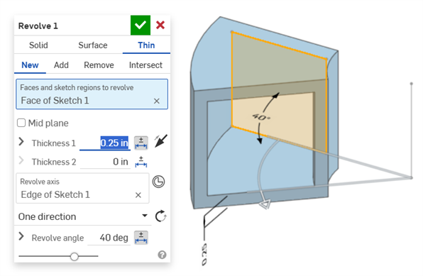
Revolve (Thickness 1 and Revolve angle dimensions):
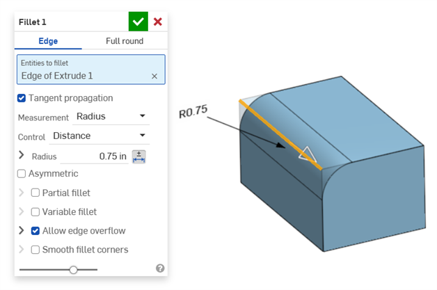
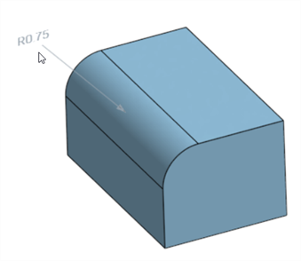
Fillet (Radius dimension):
Creating a driven fillet dimension using the Inspection table's Fillet dimension tool on the Annotation toolbar:
The Inspection panel's Dimension tool (![]() ) always uses linear or angular default tolerances. Dimensioning a filleted face using it applies a linear default tolerance type. For this reason, it is recommended to apply fillet tolerances from the Fillet feature dialog (for a driving dimension), or use the Fillet dimension from the Inspection panel (for a driven dimension).
) always uses linear or angular default tolerances. Dimensioning a filleted face using it applies a linear default tolerance type. For this reason, it is recommended to apply fillet tolerances from the Fillet feature dialog (for a driving dimension), or use the Fillet dimension from the Inspection panel (for a driven dimension).
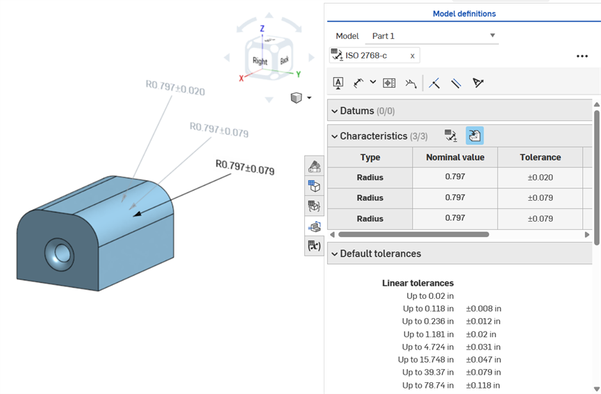
Dimensioning a fillet face: Annotated clockwise: Using the Dimension tool (driven; annotated in gray), using the Fillet dimension tool (driven; annotated in gray), and making the Fillet feature's Radius value tolerant (driving; annotated in black). All 3 dimensions are listed in the Characteristics table.
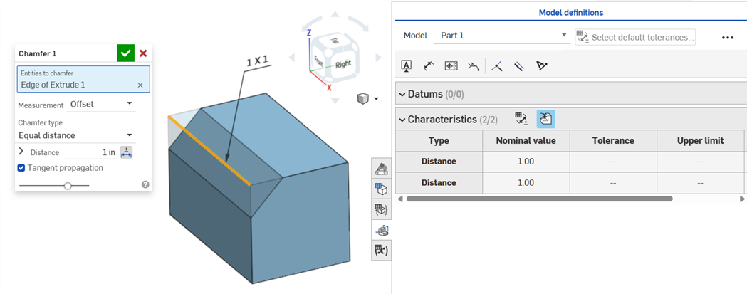
A Chamfer is defined as a distance to angle or distance to distance between a face and an edge. The Chamfer width dimensions are specified as the distance from an edge to the virtual sharp. The display for virtual sharps is added to the dimensioned edge, including a dashed curve.
-
Tolerances are not disabled When a tangent measurement is used, since they can work in certain cases, and especially when accounting for the specified tolerance.
-
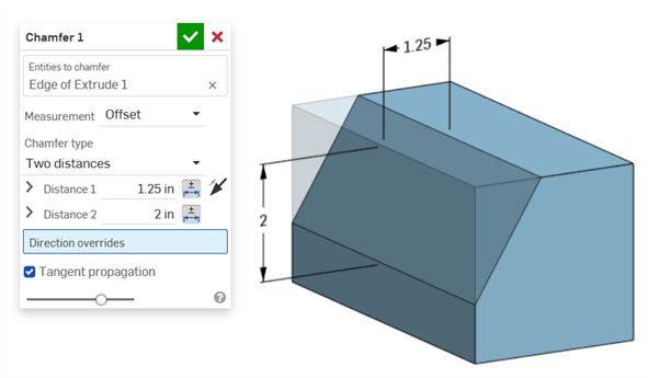
In situations where two chamfer measurements are used (Two distances or Distance and angle), the user does not have to create tolerances for both. Tolerances can be added to only one parameter, if required.
Equal distance Chamfer type displays 2 Distance tolerance values, which are reflected in the table, even though there is only one distance tolerance option in the dialog:
Two distances example:
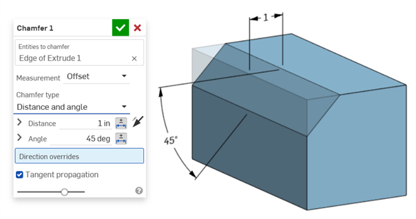
Distance and angle example:
For cases where the chamfer results in a variable distance (for example, if the chamfer is applied to a cylinder face that is perpendicularly connected to another cylinder), try selecting tangent for the Measurement, to make the distance uniform along the edge:
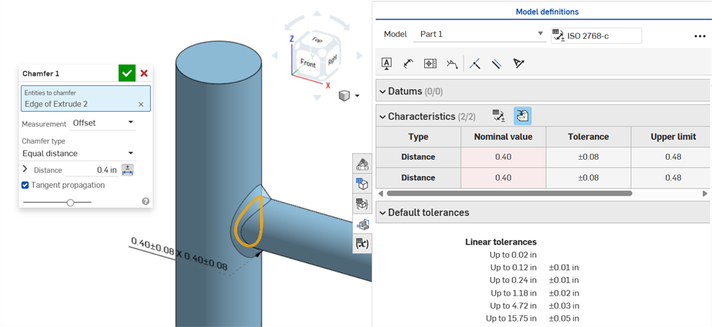
Non-uniform chamfer using an Offset measurement displaying a Nominal value error.
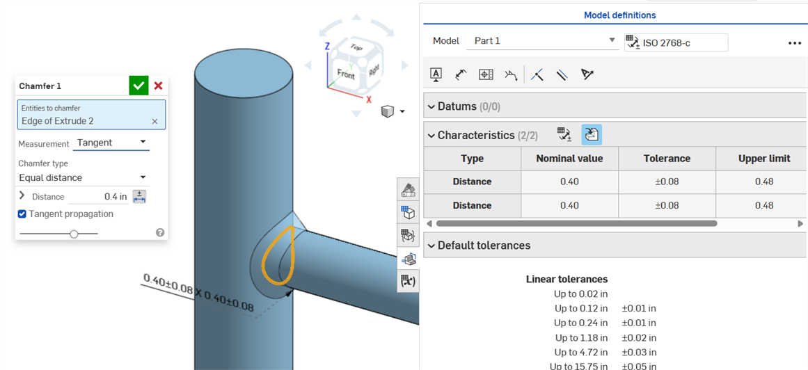
Uniform chamfer using a Tangent measurement results in a Nominal value without error.
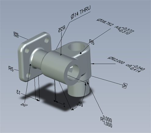
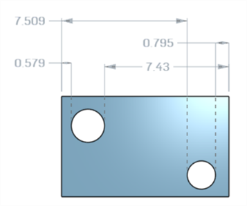
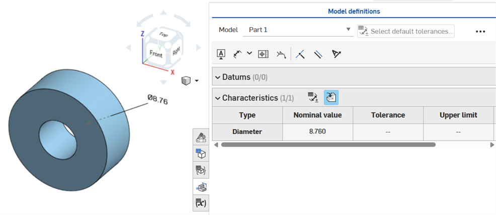
If a tolerance is placed on a hole feature, it can be displayed in the Inspection table.
Some things to keep in mind:
-
Hole dimensions are only visible as rows in the Inspection table. There are no dimensions placed in the graphics area. This is done so as not to clutter the graphics area with callouts.
-
Before hole dimensions are visible in the Inspection table, another callout (a datum, for example) must be placed on the part.
-
Only one set of dimensions (Diameter, Distance, and/or Angle) are shown per hole feature. Patterned holes or additional holes in the same feature are not dimensioned separately.
-
The custom Tip angle dimension is not currently supported and does not create a row in the Inspection table.
-
Cross-highlighting works as follows:
-
Distance (Depth) is not cross-highlighted because there are no faces at either end of the hole, and edges are not currently supported for MBD.
-
Diameter, Distance (Counterbore depth), and Angle (Countersink angle) cross-highlights a single face.
-
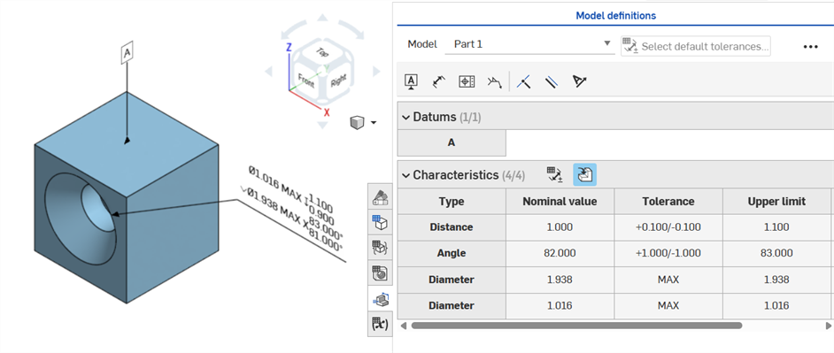
Hole dimensions are visible in the Inspection table after a Datum is added to one of the part's faces.
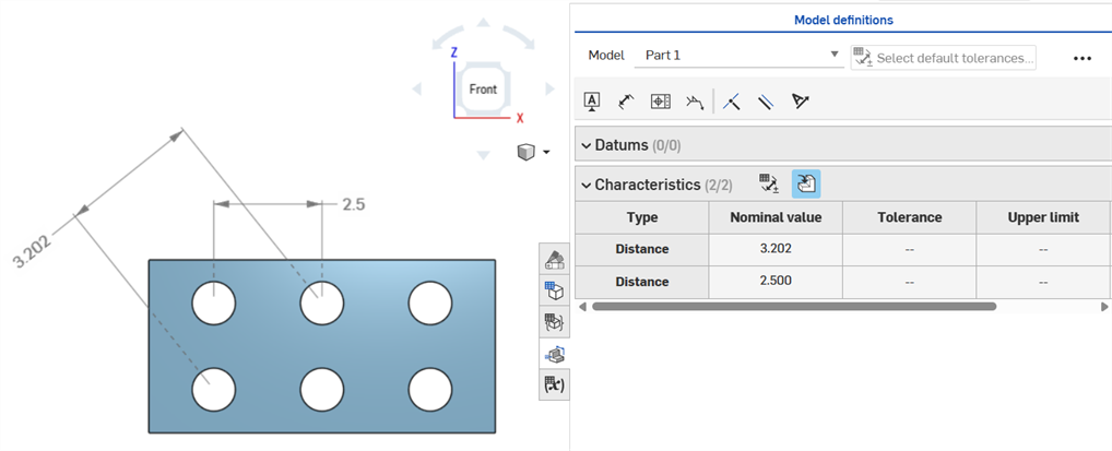
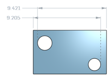
Axis distance dimensions between center circles using the Dimension (![]() ) tool:
) tool:
Minimum horizontal, diagonal, and vertical dimensions between two cylindrical faces using the Minimum dimension tool (![]() ):
):
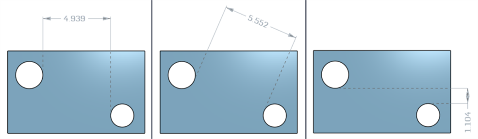
Minimum dimensions between cylinders and edges:
A minimum diagonal dimension added in a sketch (left) is displayed in the Characteristics table once the part is created (right):
Horizontal and vertical minimum dimensions cannot currently be created in a sketch.
Minimum horizontal, diagonal, and vertical dimensions between two cylindrical faces using the Maximum dimension tool (![]() ):
):
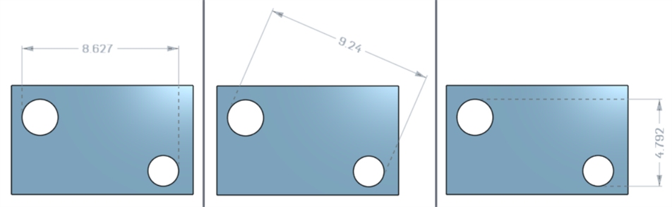
Maximum dimensions between cylinders and edges:
Maximum horizontal, diagonal, and vertical dimensions between arc faces in a slot:
A maximum diagonal dimension added in a sketch (left) is displayed in the Characteristics table once the part is created (right):
Horizontal and vertical maximum dimensions cannot currently be created in a sketch.
Thickness is displayed in the Inspection table as a Distance row.
Thin extrude (Thickness 1 dimension):
Thin revolve (Thickness 1 dimension):

A sketch centerline dimension with tolerance enabled:
If the centerline is used as the axis about which to revolve the sketch geometry, it is displayed as a Diameter dimension when the Inspection table is opened:
As annotations are added, model changes are made, and feature updates are applied, Onshape automatically attempts to validate associated MBD data.
Validations happen on a per-part basis; therefore, annotations must reference geometry from the same part or composite part.
When a characteristic is invalidated, both the annotation and the corresponding characteristic in the Inspection table are red.
Invalid characteristics fall into two categories: missing references and value mismatches.
A missing reference occurs when the geometry used to define a characteristic no longer exists or has changed in a way that breaks the association. This can result from a deleted feature, a face replacement, or another topological change.
A value mismatch occurs when the referenced geometry’s value no longer matches the defined tolerance. This can occur, for example, when a hole diameter is increased beyond the specified limits.
Resolve invalid characteristics by evaluating potential causes.
When using Compare, select faces to view their associated annotations, tolerances, and characteristics.
Validate and resolve errors by modifying the Features list and MBD annotations.
MBD errors do not create annotations or row entries in the Inspection table, unless an adjustment to the model is made that invalidates an existing annotation row entry.
Errors are displayed in red, similar to other Onshape errors:
Error generated when extruding from or into a solid. The annotation does not generate a row entry in the Inspection table.
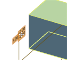
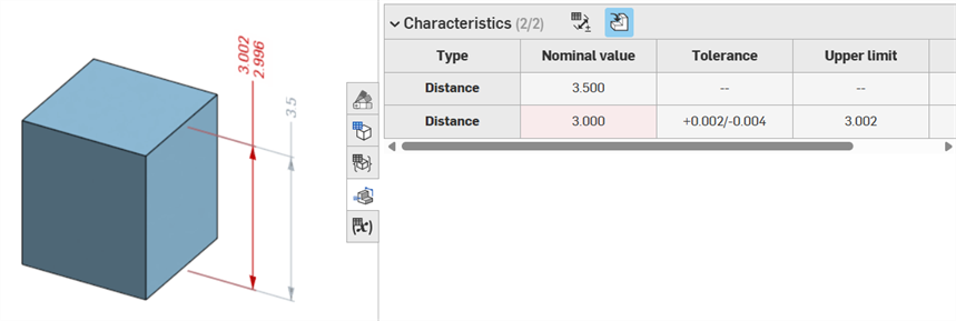
If the geometry is altered so as to invalidate a specified annotation, its corresponding annotation is red in the graphics area, and highlighted red in the Inspection table, signaling an error. For example, The top face of the box was moved .5 in., resulting in the measured value (3.5 in.) differing from the specified value (3.0 in.):
Error examples
-
A reference is missing for this annotation - Occurs when a reference is missing. For example, Part A is extruded up to the face of part B, and a tolerance is added to the Offset distance of the Part A extrusion.
-
Both faces must be from the same part - Model definitions are valid only on a per-part basis. For example, you cannot dimension the distance from a face on Part A to a face on Part B.
-
MBD annotations must always be associated with faces. Edges and vertices cannot currently be referenced.
-
Model definitions are valid only on a per-part basis. Composite parts are also valid. For example, you can dimension the distance between 2 faces on Part A or 2 faces on Part B, but not between a face on Part A and a face on Part B. To do this, first create a composite Part C from both Part A and Part B. You can then dimension the distance between these 2 faces.
-
Hovering over the Type row in the Inspection table cross-highlights the dimension in the graphics area.
-
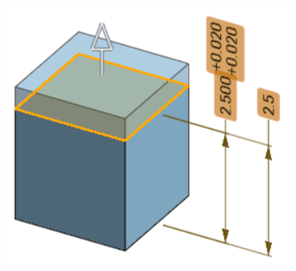
When altering geometry of a part, all associated model definitions are highlighted orange:
-
If a part or Part Studio is derived via the Derived feature, all model definitions are read-only and cannot be edited. You can still move annotations, and driven dimensions are still updated if the derived geometry is altered; however, the underlying model definitions can only be adjusted in the source Part Studio, and then updated in the Derived Feature. See Derived for more information.
-
Comments can be added to and tag tolerant sketch dimensions, feature dimensions, hole callouts, and Inspection table annotations (Dimensions, Datums, Geometric tolerances) in the graphics area. See Adding Comments on MBD annotations for more information.