Default Tolerances Library
![]()
![]()
![]()
Available in: Part Studio
A default tolerances library is generally created by Administrators and used by Company users or teams to ensure tolerances adhere to tolerance defaults. Different Default tolerances can be created inside the library folder and used for specific purposes — for example, model evaluation or machining. Once created, users access the tolerances in the Inspection table in a Part Studio, as they model their parts.
A Default tolerances library can be thought of as a list of tolerances used as an MBD template or a list of MBD tolerance rules that several users in your organization can follow.
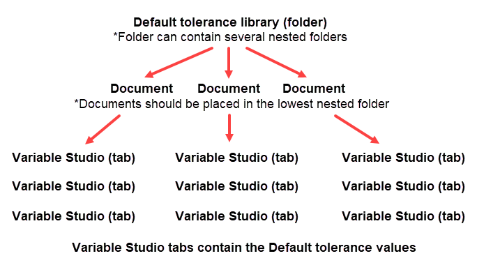
The Administrator generally creates the Default tolerances library folder structure. Once this is created, Documents are created inside the lowest folder in the hierarchy. These documents contain one or more Variable Studios that house the Default tolerance values. Multiple Default tolerance variable studios can be created in the same Document, and multiple documents can be contained inside the library folder. The hierarchy structure is outlined here:
The Default tolerances libraries folder is a special folder that contain default tolerances used as templates and applied to parts in a Part Studio. Each company can have one default tolerances library folder that is owned by an administrator and given share permissions for the company so that everyone in the company can access and use the Default tolerances libraries in the designated folder. In addition, each individual can set up one Default tolerances libraries folder for their own personal use. No special permissions are required for this folder. This personal Default tolerances libraries folder is accessed and used by the individual user.
Onshape provides standard Default tolerances in the Onshape default tolerances library. See Onshape Default tolerances library for more information.
-
Default tolerances are created and stored in Onshape folders. Depending on how you want to set up and organize your library, from the Documents page:
-
Create a folder. Company libraries must be created in the root folder. This is used for the Library field in the Select default tolerances dialog.
-
Optionally, create a second nested folder under the first. The name of the folder is used for the Standard field in the Select default tolerances dialog.
-
Optionally, create a third nested folder under the second. The name of the folder is used for the Type field on the Select default tolerances dialog.
If there are only two folders in your hierarchy, the second nested folder name is used for the Default tolerances field.
-
-
If this is a company library, from the Documents page:
-
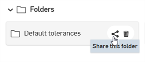
Click the Share
 icon on the root folder in your hierarchy to open the Share settings dialog:
-
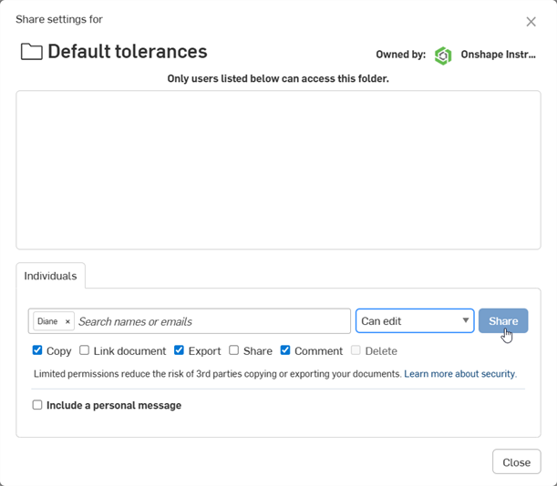
Select the Companies tab.
-
Check the Link document and Share checkboxes.
-
Click the Share button:
-
Click the Close button.
-
-
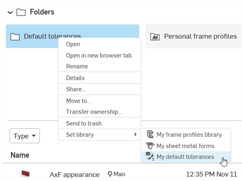
Set the library as a default by right-clicking on the root folder and selecting Set library > My default tolerances:
Once the Folder structure is set up, you need to add at least one Document into the lowest nested folder. This document must contain at least one Variable studio tab that contains default tolerance values. Here is a top-level overview of the required steps:
-
The Document is created in the lowest nested folder.
-
The Variable studio tab is inserted in the Document.
-
From the Inspection table in the document's Part Studio tab, the Default tolerance values are edited, added, and saved.
-
The Document is versioned.
-
The top level folder is updated.
Follow the detailed steps below to author a Default tolerances library document:
-
Create a new Document inside the last folder in the hierarchy created above in the Creating a Default tolerances libraries folder section. The Document name is used in the Select default tolerances dialog as the label for the bottom-most dropdown selection when a user selects a Default tolerances library.
-
Click the Insert new tab icon (
 ) and select Create Variable Studio (
 ). This is used to house your Default tolerances.
 -
Optionally, right-click and select Rename to provide a name for the Variable Studio tab. This name is used in the Select default tolerances dialog as the bottom-most dropdown selection when a user selects a Default tolerances library.
You can store multiple Variable Studios in a single document. Each Variable Studio can be set up to refer to one set of Default tolerances. You can also have multiple Default tolerances Documents in the last folder in your folder hierarchy.
-
Switch back to the default Part Studio 1 tab and create a sample part to test out the tolerances you are about to set up as default tolerances in the library.
-
Click the Inspection table icon (
 ) to open the Inspection panel.
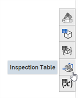
-
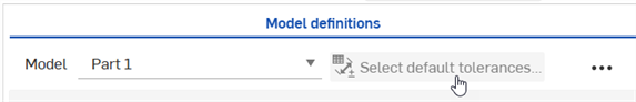
Click the Select default tolerances button:
-
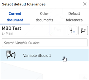
The Select default tolerances dialog opens. Click Current document, and click the Variable Studio you created from the list:
-
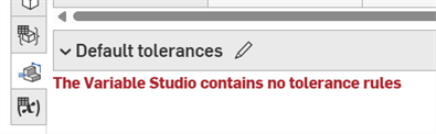
Click the X in the upper right corner to close the dialog. An error message is displayed in the Default tolerances table:
-
Click the Edit default tolerances button (
 ) to open the Editing dialog:
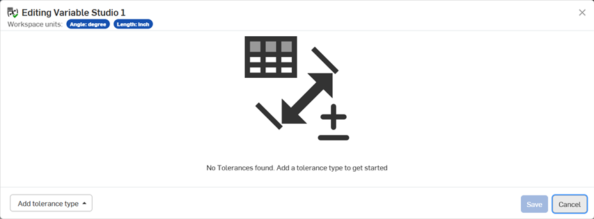
-
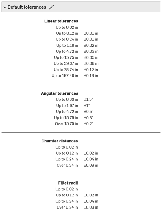
Click the Add tolerance type button at the bottom left and select from the following tolerance type options: Linear tolerances, Angular tolerances, Chamfer angles, Chamfer distances, Fillet radii, and Custom class (either With linear tolerance unit or With angular tolerance unit):
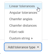
You can add as many tolerance types, and as many default tolerance values under each type, into the Default tolerances table, as required.
-
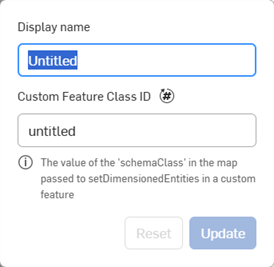
If this is a Custom class, you must enter a Display name and Custom Feature Class ID before proceeding:
-
For all other tolerance types, you are presented with 3 options to define your tolerance value type:
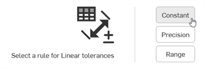
-
Constant - Defines a fixed and unchanging tolerance value, such as +/-0.01 in.

Example of a Constant default tolerance
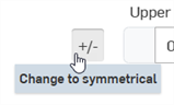
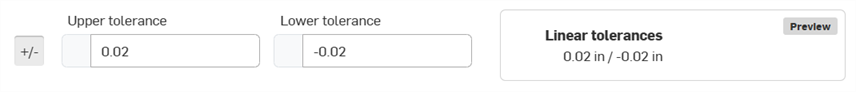
Example when switching the +/- button to change to a symmetrical tolerance
-
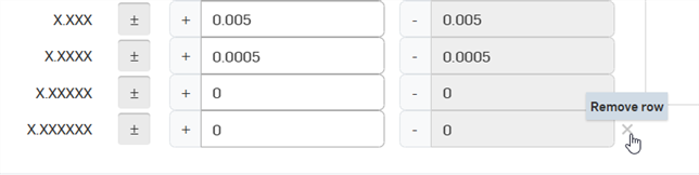
Precision - Defines a level of detail (decimal placement) for the tolerance values, such as x, x.x, x.xx, x.xxx, and so on.
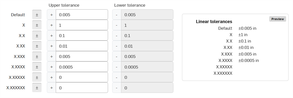
Example of a Precise default tolerance
-
Range - Defines the upper and lower limit (min/max) for tolerance values, such as +0.6 / -0.4
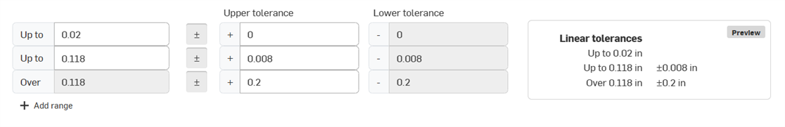
Example of a Default tolerance Range
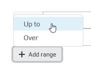
Clicking the button opens an option menu where you can select a range that is Up to or Over a specified tolerance value:
To remove a row in the Default tolerances list, click the Remove row (X) button to the right of the row. Only the last row in any Default tolerance table can be removed.
-
-
-
Add the tolerance values into the table, as required. When done, click Save. Alternatively, click if you would like to exit without any changes.
-
After saving, the default tolerances are shown in a dropdown at the bottom of the Inspection table:
-
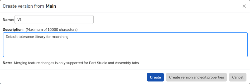
Click Create version (
 ) on the Document panel. Enter a version name and optional description. Then click the
Create
button:
) on the Document panel. Enter a version name and optional description. Then click the
Create
button:
-
Update the default tolerances library. This step must be performed each time there is a change made to the Default tolerances library document. See Updating a Default tolerances library below.
Alternatively, you can copy one of the Onshape Default Tolerances library specifications into your document as a Variable Studios tab. See Copying Onshape Default tolerances into a document. Once that is done, continue with the steps below.
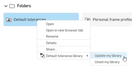
If changes are made to a Default tolerances document inside a Default tolerances library folder, the folder must be updated to have the new changes propagate to any Part Studios that reference those Default tolerances.
From the Documents page right-click on the Default tolerances library folder and select Default tolerance library > Update my library:
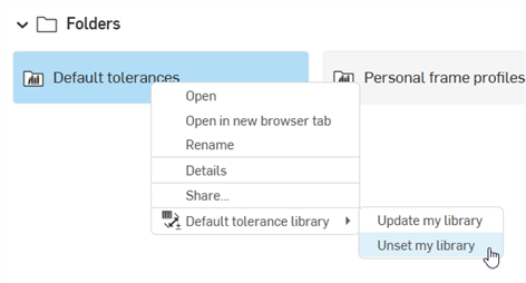
To remove a folder's designation as a user/company Default tolerances library, right-click on the folder from the Documents page and select Default tolerance library > Unset my library (shown in the first image below).
The folder changes to a standard folder icon to indicate this is a standard folder (![]() ), shown in the second image below:
), shown in the second image below:
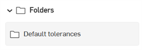
The folder and its content are not deleted.
Once the company or user Default tolerances library is created and contains one or more Default tolerances Variable Studio, they can be inserted into your Inspection table to set constraints for parts in the Part Studio.
-
From any document's Part Studio, ensure there is at least one part, and that part has a tolerance applied to one of its features (For example, an Extrude feature > Depth tolerance), or an annotation applied to one or more of its faces (a datum, dimension, geometric tolerance, or weld symbol) via the Inspection table:
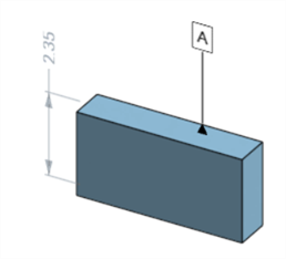
Part with a datum and dimension applied
-
On the Inspection table, click the Select default tolerances button at the top:
-
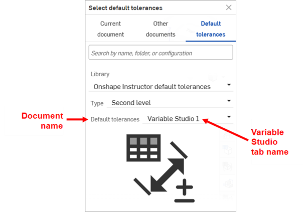
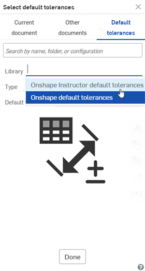
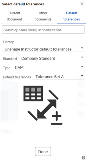
The Select default tolerance dialog opens. From the Default tolerances location, select the library (Onshape Instructor default tolerances in the first image below).
Depending how your folder structure is set up, you may also have additional dropdown selections (such as Standard and Type) from which to select.
Finally, select the default tolerances (Default tolerances (Document) and Tolerance Set A (Variable Studio) in the second image below):
-
Click Done.
The default tolerances are shown in a dropdown at the bottom of the Inspection table:
-
A non-zero blank tolerance value is supported.
-
Zero (0) tolerance values, as well as negative upper/lower(-/-) and positive upper/lower (+/+) values are supported.
-
Default tolerances library folders cannot be deleted. First unset the folder, then delete it.
-
Share permissions for Default tolerances library folders cannot be edited. First unset the folder. The share permissions can then be edited.
-
As you edit Default tolerances, they can be applied to sample part(s) in the Part Studio, to see their effect:
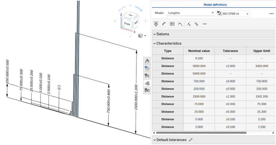
-
The Inspection panel's Dimension tool (
 ) always uses linear or angular default tolerances. Dimensioning a filleted face using it applies a linear default tolerance type. For this reason, it is recommended to apply fillet tolerances from the Fillet feature dialog (for a driving dimension), or use the Fillet dimension from the Inspection panel (for a driven dimension).
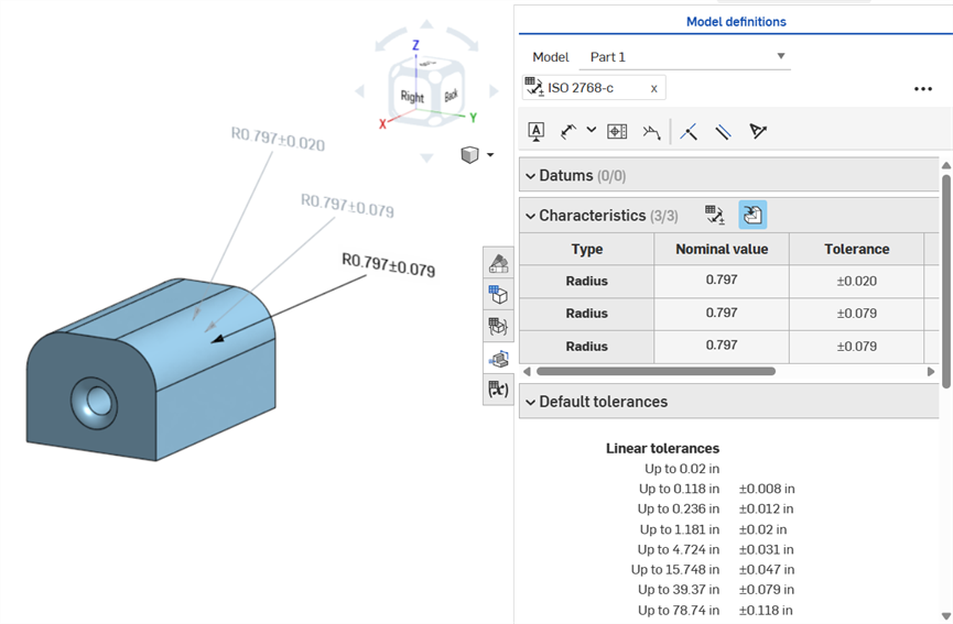
Dimensioning a fillet face: Annotated clockwise: Using the Dimension tool (driven; annotated in gray), using the Fillet dimension tool (driven; annotated in gray), and making the Fillet feature's Radius value tolerant (driving; annotated in black). All 3 dimensions are listed in the Characteristics table.