

Only available for.
Available in: PCB Studio
Import Rigid-flex PCBs into Onshape from Altium 365 or an IDX file, or create Rigid-flex PCBs in Onshape that can be exported to an IDX file.
A rigid zone is any board or component. These can be modeled in a Part Studio using sketches and Extrude features. Flex zones are flexible PCBs that are modeled in a Part Studio using sketches and Flex PCB model features.
See Moving ECAD data into and out of Onshape if creating a board that does not contain any flex components.
 Steps: Creating a rigid-flex PCB for export to an IDX file
-
In a Part Studio, sketch rigid and flex regions.
Use simple geometry such as planar and cylindrical surfaces, lines, and arcs. Avoid using splines, beziers, and complex free-form surfaces. These tools may lead to approximated geometry during import and unexpected shape changes.
-
Use the Extrude feature to create rigid regions.
-
Use Flex PCB model features to create flex regions. It is recommended to use 1 feature per flex zone, if possible
-
Add Mate connectors in the Part Studio.
Ensure the connectors are attached (owned by) the geometry, not the sketch. If the sketch owns the mate connector, its visibility in the Assembly may fail or imported Assemblies may not be accurate.
Select the face/zone for the Origin entity, and ensure the Attachment is set To selection. This ensures the Mate connectors follow the flat/fold configurations and geometry edits.
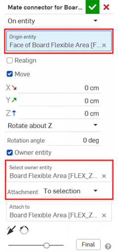
Avoid creating Mate connectors later in the Assembly. Assembly-based mate connectors may not update correctly when flex zone lengths change, bend locations change, or additional folds are introduced.
-
Define component locations.
When sketching, use face centroids for centrally-located connections.
For precise custom locations, create helper sketches, add reference lines, and use midpoint references. Then place mate connectors from sketch geometry.
When components are expected on flexible regions, use the following workflow to ensure components move correctly when the rigid-flex PCB is flattened/folded:
-
Create sketches on flex zones.
-
Mark component locations.
-
Create mate connectors at those locations.
-
Attach connectors to the flex regions.
-
-
Add any Hole geometry required.
Create all required plated and non-plated holes before transferring the design to PCB Studio.
Add mounting holes, tooling holes, alignment holes, and other mechanical features as part of the board definition.
Fully constrain hole locations to the appropriate board region.
-
Add Bends to the flex zones.
Unfold all flex regions onto the same reference plane and do not unfold different flex regions relative to different planes. This ensures predictable PCB Studio imports, prevents placement discrepancies, and improves MCAD/ ECAD synchronization.
Optionally, other sheet metal features, such as Flange or Hem can be used when modeling flex PCB zones.
-
Use Finish flex PCB model features to complete the flex zones. Only 1 flex zone can be finished per feature.
-
Add the hole Tag feature to define hole parameters. Review all tagged holes before export.
-
At a minimum, create 2 configurations in the Part Studio: Flattened and Folded:
-
Click the Configuration panel icon (
 ) to open the panel.
 -
Click Configure part studio.
-
Click the Configure features button.
-
For each Flex PCB zone, click its Finished PCB model feature in the Features list, click the Unfold all parameter in the feature, and click X to close the feature.
-
Click Done on the message at the top of the graphics area.
-
Rename the Default row Flattened.
-
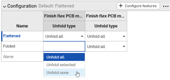
Create another row and name it Folded and press Enter.
-
For all the Finished flex PCB features in the Folded row in the table, click the dropdown and select Unfold none:
Optionally, add the following partial unfolded configurations for:
-
Manufacturing fixtures
-
Test jigs
-
Inspection setup
-
-
Name all zones correctly. See Naming parts for more information.
-
Build the Assembly from the flat configuration:
-
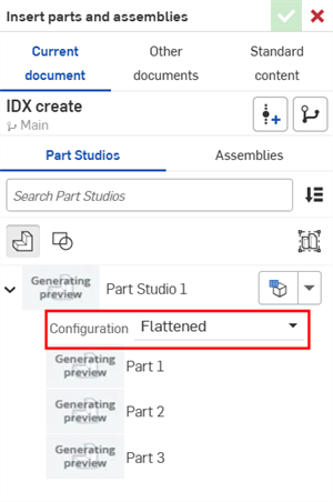
Insert the Part Studio with the Flattened configuration:
-
Right-click on the primary rigid zone in the Instances list and select Fix to make it immovable in the Assembly. mate everything else relative to it.
-
Mate all zones and components, relative to the fixed primary rigid zone.
-
-
In the PCB Studio, sync the Assembly from Onshape using the flat configuration. See Translate the CAD data to ECAD for more information. ECAD tools expect flattened board definitions.
-
Export to IDX 4.0 file format. See Export the data and download the file for more information.
Notes
-
Model a rigid-flex PCB as separate rigid and flexible regions, establish all mating relationships in the Part Studio before assembly, and always maintain a clear flat-to-folded workflow using configurations.
-
It is important to invest time in correct mate connector placement, naming conventions, and configuration setup in order to prevent downstream issues when moving between MCAD, PCB Studio, and ECAD.
-
Always create rigid zones using the Extrude feature and flex zones using the Flex PCB model feature; ensuring they are modeled separately.
-
For rigid zones, use realistic board thicknesses (for example, 1.6 mm, where appropriate, and model each zone as an independent part.
-
For flex regions, model each zone as a separate flex zone connecting to rigid sections via mate connectors. This enables proper flat/fold behavior, and compatibility with PCB Studio/MCAD to ECAD transfer.
-
Reference designators are preserved during import and export.
Steps: Importing a rigid-flex PCB into PCB Studio from an IDX or Altium file
When importing an IDX- or Altium-generated rigid-flex PCB into PCB Studio, the Part Studio, Assembly, Mate connectors, configurations, and flat/folded states are automatically created. This eliminates much of the manual setup required if first creating the board in a Part Studio.
-
From a PCB Studio, do one of the following:
-
To import an IDX file:
-
Click the Import ECAD files icon (
 ).
). -
Click the Choose files button.
-
Locate the IDX file on your device and select it.
-
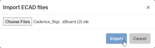
Click the Import button:
-
-
To import an Altium file:
-
Click the dropdown arrow to the right of the Import ECAD files icon (
) -
Click the dropdown menu button (
 ) and select Import from Altium 365: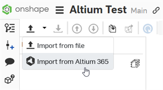
-
Locate and access the rigid-flex PCB in your Altium workspace. See Downloading an Altium workspace project into a PCB Studio tab for full instructions.
-
-
-
The board is imported into the PCB Studio:
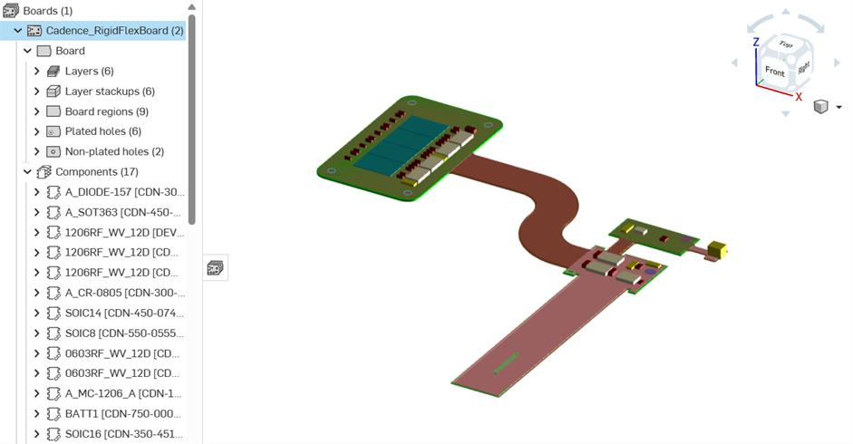
Flexible regions are colored brown, while rigid regions are colored green.
-
Follow the instructions in the Translate the ECAD data section to sync the data into an Onshape Part Studio and Assembly.
After sync, the Part Studio and Assembly for the rigid-flex PCB are created:
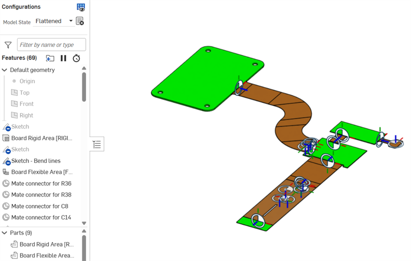
Part Studio
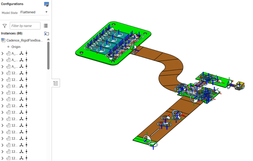
Assembly
In the Part Studio and Assembly, 2 configurations are created:
-
Flattened - The default configuration displaying the flat view for flex zones.
-
Folded - The alternate configuration displaying the folded flex zones
To prevent accidentally moving the assembly, the board instance is automatically fixed:
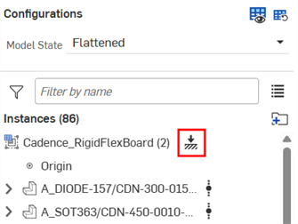
In the Part Studio, the configurations are excluded from affecting configured properties.
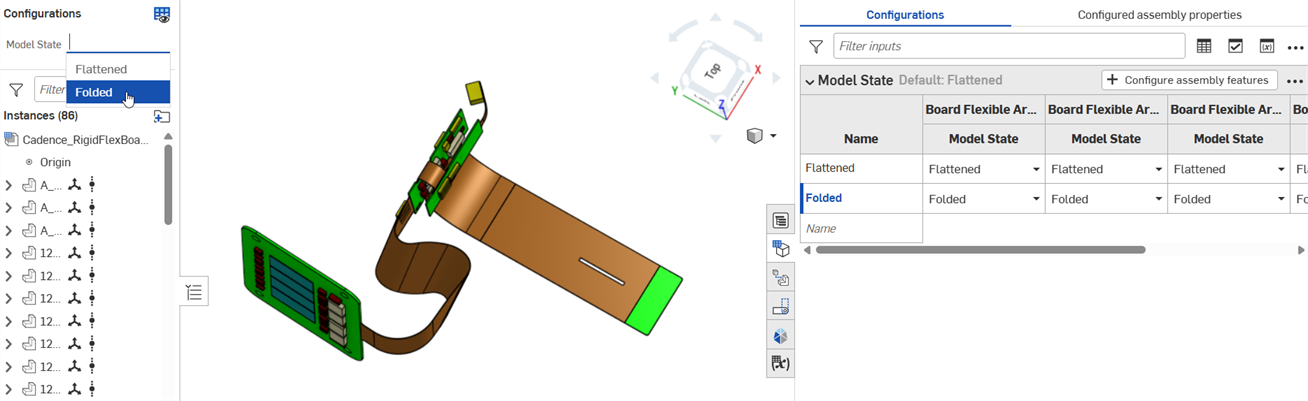
Folded configuration (Mate and Mate connectors hidden)
-
-
Follow the instructions in the Translate the CAD data to ECAD section to sync the data into an Onshape Part Studio and Assembly.
Notes
-
When Syncing to Onshape, Explicit Mate connectors are always created on components attached to flex zones, and between flex zones. The one exception is if the board is not selected (on subsequent syncs). In this case, board rigid zones are not mated to flex zones.
-
Keep-In / Keep-Out Areas are not automatically associated with folding regions and may require manual mating. They can also span multiple board zones.
-
When exporting to IDX, flex zones may occasionally be mistaken as rigid. It is important to validate all exports before any production use.
-
Reference designators are preserved during import and export.
-
PCB Studio supports importing Rigid-flex PCBs from Altium 365:
-
In Altium, ensure bend lines intersect the entire region.
-
Decals are not shown on bend regions after syncing to Onshape:
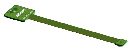
Before syncing to Onshape (decal shown in green in the PCB Studio tab)
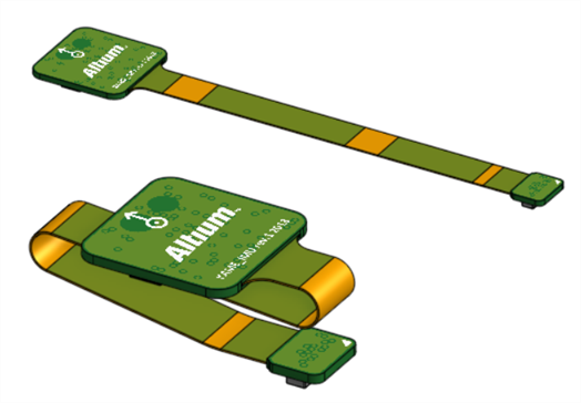
After syncing to Onshape, in the Assembly: Flattened (top); Folded (bottom). Decals missing on the orange bend regions (in the Assembly tab).
-