 Flex PCB Model

Available in: Part Studio
Create flexible PCB parts by converting existing parts, extruding sketches, or thickening faces or sketches. Operations on PCB models are automatically represented as a flat pattern, and joints and bends are listed in a table.
 Flex PCB model steps: Convert
Create a flex PCB model by enclosing existing parts:
- While in a Part Studio, click the Flex PCB model icon (
 ) on the Feature toolbar.
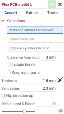
- Select the type of Flex PCB model operation: Convert.
- Select the parts and surfaces to convert.
- Select the faces to exclude from the operation.
- Select the edges or cylinders to create bends; edges not selected are made into rips or, in the case of arcs and splines, are made into tangent joints.
- Specify applicable options:
- Clearance from input - The relative offset between the flex PCB and the part selected to be enclosed by the flex PCB.
- Include bends - Check this to include the bend within the clearance value.
- Keep input parts - Keep the selected parts (enclosed by the flex PCB) or not.
- Thickness
- The thickness of the flex PCB. Click the Opposite direction arrow icon (
 ) to flip the flex PCB to the other side.
- Bend radius - Sets the inside radius of the bends created.
- Flip direction up - Reverses the orientation of the flex PCB model and flat view. This is useful when defining whether bends are up or down, relative to the model.
- Default bend K Factor - The fraction of material thickness on which the neutral axis lies on a bend. (Default is 0 for models created in a Part Studio tab and 0.5 for models created in a PCB Studio tab).
-
Click the checkmark icon (
 ) to accept the feature; the Flex PCB model is listed in the Features list.
- Apply any other specific flex PCB features now (for example, bend, joint, or hem).
- Click Finish flex PCB model and continue with the steps, as outlined in Creating a rigid-flex PCB for export to an IDX file.
Flex PCB model steps: Extrude
Create a flex PCB model by extruding sketch curves:
- While in a Part Studio, click the Flex PCB model icon (
).
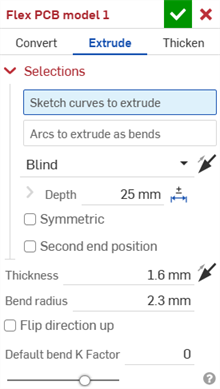
- Select the type of Flex PCB model operation: Extrude.
- Select the sketch curves to extrude.
- Select the Arcs to extrude as bends.
- Specify applicable options:
- End type - Select one of the following options: Blind, Up to next, Up to face, Up to part, Up to vertex. Click the Opposite direction arrow icon () to flip the end direction.
- Depth - Drag or set the depth numerically.
- Symmetric - Select this option, available for Blind end types only, to a specified total distance, half the distance in both directions about the sketch plane.
- Second end position - Check to extrude in a second end position about the sketch plane.
Extruding in a second end position offers all the same end conditions and a separate depth field, as well as the option to create a draft (with the sketch plane as the neutral plane) and flip the draft in the opposite direction.
- Thickness - The thickness of the flex PCB. Click the Opposite direction arrow icon () to flip the flex PCB to the other side.
- Bend radius - Sets the inside radius of the bends created.
- Flip direction up - Check to reverse the orientation of the flex PCB model and flat view. This is useful when defining whether bends are up or down, relative to the model.
- Default bend K Factor - The fraction of material thickness on which the neutral axis lies on a bend. (Default is 0 for models created in a Part Studio tab and 0.5 for models created in a PCB Studio tab).
- End type - Select one of the following options: Blind, Up to next, Up to face, Up to part, Up to vertex. Click the Opposite direction arrow icon (
-
Click the checkmark icon (
) to accept the feature; the Flex PCB model is listed in the Features list.
- Apply any other specific flex PCB features now (for example, bend, joint, or hem).
- Click Finish flex PCB model and continue with the steps, as outlined in Creating a rigid-flex PCB for export to an IDX file.
Flex PCB model steps: Thicken
Create a sheet metal model by thickening faces, surfaces or sketch regions:
- While in a Part Studio, click the Flex PCB model icon (
).
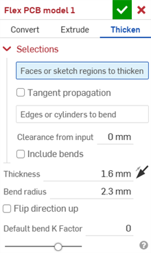
- Select the type of flex PCB model operation: Thicken
- Select the faces or sketch regions to thicken.
- Check Tangent propagation to extend the flex PCB zones to surrounding edges.
- Select the edges or cylinders to create bends; edges not selected are made into rips or, in the case of arcs and splines, are made into tangent joints.
- Specify applicable options:
- Clearance from input - The relative offset between the flex PCB and the part selected to be enclosed by the flex PCB
- Include bends - Check to include the clearance for bends.
- Thickness
- The thickness of the flex PCB. Click the Opposite direction arrow icon () to flip the flex PCB to the other side.
- Bend radius - Sets the inside radius of the bends created.
- Flip direction up - Check to reverse the orientation of the flex PCB model and flat view. This is useful when defining whether bends are up or down, relative to the model.
- Default bend K Factor - The fraction of material thickness on which the neutral axis lies on a bend. (Default is 0 for models created in a Part Studio tab and 0.5 for models created in a PCB Studio tab).
-
Click the checkmark icon (
) to accept the feature; the Flex PCB model is listed in the Features list.
- Apply any other specific flex PCB features now (for example, bend, joint, or hem).
- Click Finish flex PCB model and continue with the steps, as outlined in Creating a rigid-flex PCB for export to an IDX file.